Eaton i-on Series Engineering Manual
Next generation
Hide thumbs
Also See for i-on Series:
- Engineering manual (178 pages) ,
- Administration and user manual (63 pages) ,
- Administration and user manual (67 pages)

Related Manuals for Eaton i-on Series


Summary of Contents for Eaton i-on Series
- Page 1 i-on Next Generation Security System Engineering Guide Issue 1 Control unit software version 5.0...
-
Page 2: About This Guide
CONTENTS OF THIS DOCUMENT SHALL NOT BECOME PART OF OR MODIFY ANY CONTRACT BETWEEN THE PARTIES. In no event will Eaton be responsible to the purchaser or user in contract, in tort (including negligence), strict liability or other-wise for any special, indirect, incidental or consequential damage or loss whatsoever, including but not limited to damage or loss of use of... -
Page 3: Table Of Contents
Contents About this Guide ....................... ii Other Publications ......................ii Chapter 1: Introduction .................. 1 Introduction to i-on Next Generation control units ............1 Summary of features ....................1 System architecture and supported peripherals ............... 3 System bus ........................3 Part-setting and partitioned modes ................ - Page 4 Code lockouts ......................22 Transferring to another keypad ................... 23 Using Downloader or the web interface ..............23 Exiting the Installer menu ....................23 Resetting (defaulting) the system ................... 24 Restoring control unit factory defaults ................. 24 Resetting device addresses ..................24 Defaulting access codes .....................
- Page 5 Add Outputs ........................ 63 Edit Outputs ........................ 63 Wired Outputs ........................ 70 Panel .......................... 70 Plug-By Outputs ......................70 Plug-by outputs on an EXP-PSU ................71 Custom Outputs ......................71 Example ........................71 Chapter 8: Setting Options and Partitions Menus ........72 About these menus ......................
- Page 6 Chapter 9: System Options Menu ............... 83 Wired Zone Type ......................83 User Access ........................83 HUA Keys Active ......................83 Quick Set ........................83 Quick Omit ........................84 User Code Reqd ......................84 2 Way Replies......................84 2 Way Set Instant ....................... 84 Duress Enable ......................
- Page 7 Supervision ........................96 Jamming ......................... 96 Force Set ........................97 Tamper Omit ........................97 CSID Code ........................97 Silence Alerts ......................... 98 Mains Fail Delay ......................98 External PSUs ......................99 Set Time & Date ......................100 SNTP Time Sync ......................100 Panel Tamper Return ....................
- Page 8 IP Address ........................ 117 IP Subnet Mask ......................117 Gateway IP Address ....................117 DNS IP Address......................117 Module Ethernet ....................... 117 GPRS Module ......................118 Dynamic DNS ....................... 118 Downloading ........................ 119 Account ........................119 Connection Type....................... 119 Rings to Answer......................120 Answer On One Ring ....................
- Page 9 Logging Tamper Events ....................131 Logging Software Updates ................... 131 Chapter 13: About Menu ................132 Panel ..........................132 Expanders ........................132 Keypads ........................132 Comms ......................... 132 Panel Ethernet ......................132 Module ........................133 Zone Mapping ......................133 Zone Numbers ......................133 Zone Addresses......................
-
Page 11: Chapter 1: Introduction
(for 2-way radio keypads). An on-board radio transceiver, which has a range of up to 500m and supports devices such as radio detectors, Eaton radio siren/strobe units and radio outputs. Built-in Alarms Receiving Centre (ARC) IP communicator. - Page 12 Introduction On-board outputs and wired zones (depending on the control unit). On-board connections for a wired siren/strobe unit. On-board connections for an external loudspeaker. Table 1: Overview of features Feature EN 50131 security grade Max on-board radio zones Max on-board wired zones (Note 6) Max zones on expanders, keypads, etc.
-
Page 13: System Architecture And Supported Peripherals
Introduction Note 1: Each partition has one part set within it. Note 2: A 2-way radio keypad (KEY-RKPZ) requires a KEY-RKBS base station wired to the control unit. Up to two radio keypads can connect to the same base station, but this feature cannot be used to increase the total number of wired and 2-way radio keypads beyond the limit shown in Table 1. -
Page 14: Part-Setting And Partitioned Modes
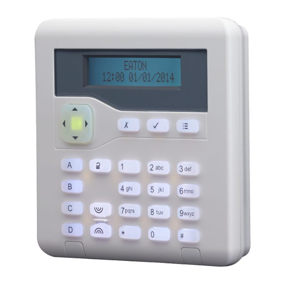
Introduction Each device on the bus has a unique address. A device obtains its address from the control unit either during the commissioning stage of a new installation, or when the installer adds the device from the Installer menu. Each device stores its address in non- volatile memory. - Page 15 Introduction Features The keypads feature: A two-line by 20-character backlit LCD display (not available on i-RK01). An illuminated four-way switch (the “navigation key”), which is used to navigate through menus (not available on i-RK01). LEDs behind the navigation key, which show the fault status of the system. ...
-
Page 16: Alarm Communicators
Introduction You cannot exit the Installer menu from an engineer keypad, so after you have finished, you will need to disconnect the engineer keypad and exit the Installer menu from a standard keypad. KEY-EP external proximity tag reader Many keypads include a proximity tag reader. The KEY-EP is an external proximity tag reader, which can connect to a keypad and allows the system to be to set or unset externally. -
Page 17: Detectors (Zones)
Introduction Detectors (zones) Detectors are the physical devices that detect alarm conditions. A zone is the lowest-level item within the intrusion system that can be set or unset. Note: Although it is possible to connect detectors in series and therefore to have more than one detector in the same zone, it is not normal practice. -
Page 18: Expanders
Introduction 739rEUR-00 Sentrol glass-break without tamper DET-RWATER Flood detector DET-RARB Request-for-assistance button 703R Universal transmitter Expanders Expanders provide additional connections for zones, outputs and loudspeakers, up to the limits specified in Table 1. Wired expanders Wired expanders connect directly to the bus. The EXP-W10 is supported, which provides connections for: ... -
Page 19: Control Unit Usb And Ethernet Ports
Introduction o Relay – These provide voltage-free changeover contacts. You connect one side of the external device to the C (Common) terminal, and the other to either NO (Normally Open) or NC (Normally Closed) side of the relay, depending on the application. ... -
Page 20: Loudspeakers
Introduction External radio sirens/strobes Radio siren/strobe units can communicate directly to control units that have built-in radio communications, or to radio expanders. The following external wired siren/strobe units are supported: 760ES External radio sounder. SND-REXT External radio siren/strobe unit. Internal sounders An internal sounder indicates alarms, entry tones, exit tones and other conditions. -
Page 21: Other Supported Radio Devices
Introduction Other supported radio devices The following additional radio devices are also supported DET-RSURV01 Radio Site Survey Tool. 770REUR-00 Wireless Accessory Module (WAM). 762REUR-00 Radio receiver. 768REUR-00 Radio receiver. Page 11... -
Page 22: Chapter 2: Planning The Installation
Chapter 2: Planning the Installation Choosing the installation locations When planning the installation, consider the following recommendations concerning the locations of where to install the control unit and other devices. Note: Also refer to the device installation instructions for any further guidance. General requirements Do not locate any device: ... -
Page 23: External Sirens
Planning the Installation External sirens These must be located out of reach of intruders and vandals, but must be easily visible for maximum deterrence. Checking power availability You must make sure that: The control unit's power supply will have sufficient capacity to power all connected devices. -
Page 24: Worked Example
Planning the Installation Worked example The following shows a simplified example of checking power availability. Device Current Control unit PCB (i-on30R) 90mA i-dig02 at 20mA 20mA 10 x PIRs at 15mA each 150mA 1 x wired expanders 20mA 2 x KEY_FKPZ at 25mA each (backlights off) 50mA Siren (quiescent) 35mA... -
Page 25: 4-Wire Cc
Planning the Installation Alarm Tamper Figure 2. FSL Connections (using 2k2 and 4k7 resistors) The End-of-Line (EOL) and alarm contact resistors can be any of the following values (respectively): 2k2 and 4k7, 1k and 1k, 2k2 and 2k2, or 4k7 and 4k7. The resistance bands for FSL are as shown in Table 3. -
Page 26: 2-Wire Cc
Planning the Installation Table 4: 4-Wire CC Zones Equipment FSL or 2-wire CC 4-wire CC Panel with 10 on-board zones 10 zones 5 zones EXP-PSU and original EXP-W10 10 zones 5 zones EXP-WCC and new EXP-W10 10 zones 10 zones Keypad with 2 on-board zones 2 zones 1 zone... -
Page 27: Bus Termination
Planning the Installation Bus termination In some cases, the ends of the bus may need to be terminated to improve performance in electrically noisy environments or where there are long cable runs. The control unit and bus devices have a termination link on their PCB. Fitting a jumper to the link adds a termination to the cable. -
Page 28: Using Remote Power Supplies
Planning the Installation Table 5: Voltage drop along cable Current Cable Length (Standard 7/0.2 alarm cable) Drawn 100m 60mA 0.10V 0.19V 0.29V 0.38V 0.48V 0.58V 0.67V 0.77V 0.86V 0.96V 80mA 0.13V 0.26V 0.38V 0.51V 0.64V 0.79V 0.90V 1.02V 1.15V 1.28V 100mA 0.16V 0.32V... -
Page 29: Chapter 3: Getting Started
Chapter 3: Getting Started Once all wiring is complete, the system is ready to be programmed. This section provides an overview of how to carry out this task. Later sections of this guide explain the configuration options in more detail. About the user interface The control unit displays configuration options in menus. -
Page 30: Initial Power-Up Procedure
Getting Started Initial power-up procedure WARNING: During initial power-up, keypad sounders, internal loudspeakers and wired sirens may give an alarm tone. If you are working at the top of a ladder, make sure that the sudden noise does not startle you and cause a fall. Note: ... - Page 31 Getting Started Select the wiring type you intend to use for wired zones (page 7): This determines the default wiring type for the control unit and any attached bus devices, such as wired expanders. You can change the control unit's wiring type through Installer menu –...
-
Page 32: Entering The Installer Menu
Getting Started Entering the Installer menu Entering the Installer menu allows you to configure the system using the options provided. While you are logged in: The system will not generate alarms. You are, for example, able to open the lid of the control unit without generating an alarm. -
Page 33: Transferring To Another Keypad
Getting Started Transferring to another keypad While in the Installer menu, you can transfer to any other keypad without leaving the Installer menu. To do this, simply go to any other keypad and enter the Installer access code. The new keypad will pick up your position in the Installer menu. The keypad you have left will exit the Installer menu. -
Page 34: Resetting (Defaulting) The System
Getting Started Resetting (defaulting) the system Restoring control unit factory defaults You can remove all configuration from the control unit using System Options – Restore Defaults – Factory Defaults (see page 92). You must restore defaults from a keypad; you cannot do this from a PC. -
Page 35: Chapter 4: Addressing And Zone Numbering
Chapter 4: Addressing and Zone Numbering This chapter explains how the control unit assigns addresses, such as to bus devices, outputs, detectors. It also explains how the control unit maps zone numbers to detectors. Bus device addresses The control unit keeps a record of the address it allocates to each device on the bus. Each device also stores its address locally in non-volatile memory. -
Page 36: Output Addresses
Addressing and Zone Numbering When reporting alarms to an alarms-receiving centre using CID or SIA protocols, the control unit reports each device as a number (not as an address). For example: Radio Siren Ext.01 to Ext.20 WAMs WAM01 to WAM20 Note that the highest number will depend on the control unit. -
Page 37: On-Board Wired Detectors
Addressing and Zone Numbering Figure 8. Example of Detector Addressing and Zone Numbering (i-on40H) On-board wired detectors Wired detectors attached directly to the control unit (if applicable) use the following address: On-Board Wired Zone Number Detector Address FSL* and 2-wire CC wiring PAN<Z00 to PAN<Z09 000 to 009 4-wire CC wiring... -
Page 38: Detectors Attached To An Expander
Addressing and Zone Numbering Detectors attached to an expander Detectors attached to an expander take the address An<dd<ii (e.g. W1<04<00), where: One or more letters showing the device type: W=Wired Expander, R=Radio Expander. Bus number (always 1). dd = Bus device number (see page 25). ii = Input number. - Page 39 Addressing and Zone Numbering number 058 to terminals Z1. When you add the next keypad, the control unit allocates the zone numbers 057 to terminals Z2 and 056 to terminals Z1 on the new keypad. Table 7 shows an example. Table 7: Keypad –...
- Page 40 Addressing and Zone Numbering Figure 9. Example zone availability (i-on30R) Page 30...
-
Page 41: Chapter 5: Installer Menu Map
Chapter 5: Installer Menu Map Important: Where noted below the defaults listed enable the control unit to comply with EN50131 requirements. If you change those settings, the installation may no longer comply. If the control unit does not comply with EN50131, you must remove any labelling that indicates compliance. - Page 42 Installer Menu Map Address Bus Device Radio Edit Expander Expander R1-01... Expanders “Exp. R1-nn” Name Partitions Partition 1 Visible only in a partitioned system. Loudspeaker Volume Delete Expander Enable Expander Yes (all expanders enabled). Replace Expander Address Bus Device Wired Edit Keypad Keypad K1-51...
- Page 43 Installer Menu Map Name: “Key A” Key A Setting: Partition 1 Full Set OR Full Set in a Part Setting System Name: “Key B” Key B Setting: Partition 2 Full Set OR Part Set B in a Part Setting System Name: “Key C”...
- Page 44 Installer Menu Map On Time 1 second Exp. W1-nn EDIT output Name Type Not used Polarity Normal Pulsed Partitions All outputs allocated to all Visible only in a partitioned system. Partitions Zones None Delay 0 seconds Visible when Pulsed set to “Yes”. On Time 1 second Keypad k1-nn...
- Page 45 Installer Menu Map Siren Time 15 minutes Pt.set Final Exit Final exit Pt.set Entry Route Entry Route Strobe on Set Strobe on Unset Exit Mode Timed Set Remote Set Exit Time Local Set on ER None Calendar Set Visible only in a partitioned system. 3 Partitions (only shown in a partitioned system) “Partition n”...
- Page 46 Installer Menu Map Warning Tone Audible Delete Event Add Exception Exception 01... Exception Start 00:00 Time Exception Start 01/01 Date Exception End 00:00 Time Exception End 01/01 Date Edit Exception Exception 01... Name "Exception nn" Start 00:00, 01/01 00:00, 01/01 Delete Exception 4 System Options Panel Zones...
- Page 47 Installer Menu Map Installer configured Installer Code Panel name Keypad text Disabled Remote needs Entry Disabled Remote needs Entry PrtSt Disabled RKP needs Entry Disabled RKP Entry PrtSt HUA Response Audible Visible only for part-setting system. PZ Unset Response Silent Visible only for part-setting system.
- Page 48 Installer Menu Map Fast Fmt channels Channel 1: Fire Alarm Visible only when Report Type is Fast Channel 2: Hold Up Alarm Format. Channel 3: Burglar Alarm Channel 4: Open / Close Channel 5: Zone Omit (System) Channel 6: Tamper Channel 7: Confirmed Alarm Channel 8: General Fault CID/SIA Events...
- Page 49 Serv. On Exit Eng Disabled Service Call Num Tel No 1 Time Window Start 00:00 Visible only for UK systems. Downloader must be enabled by Eaton. Time Window End 06:00 Next Service Date 24/12/2015 Service Interval 180 days Start Service Call 6 Test Ext.
- Page 50 Installer Menu Map Partition Expanders Zones Visible only is systems that have wired Zone Resistances zones. Detectors Signal Radio Keypads i-rk01 Strengths KEY-RKPZ External Sirens WAMs Internal Sounders Radio Outputs Outputs Wired Outputs Plug-by outputs Expander Outputs Remotes User Hold Up Alarms Prox Tags Panel Ethernet Reporting...
-
Page 51: Chapter 6: Detectors/Devices Menu
Chapter 6: Detectors/Devices Menu This chapter explains the options in the Detector/Device menu. Detectors Add/Del Detectors This option allows you to add and delete radio detectors (zones). Adding radio detectors To add a radio detector: Select Panel (if applicable) or a radio expander to assign that detector to. Select a zone. - Page 52 Detectors/Devices Menu If you program a radio zone but the control unit does not have a detector learned for that zone, the keypad displays “Zone programmed but not learned” when you leave the Installer menu. Name You can give each zone a 12-character name. The control unit displays this name when, for example, you select the zone or the zone generates an alarm.
- Page 53 Detectors/Devices Menu Normal Alarm - NA (03) When triggered, a zone of type Normal Alarm will start an alarm provided the system is set. When the control unit first learns a radio detector, the zone type defaults to Normal Alarm. 24 Hour Alarm - 24 (04) Activating this zone while the system (or partition) is unset causes an internal alarm (internal sounders and speakers only).
- Page 54 Detectors/Devices Menu In a part-setting system, the keyswitch can full set or unset. As with momentary keyswitches, you can allocate the zone to one or more partitions (see above). When the user opens the keyswitch contacts, the control unit sets the allocated partition.
- Page 55 Detectors/Devices Menu the control unit activates any output of type External PSU Fault and causes an alert that displays “External power fault” on the keypad. If the alarm system is set, the control unit logs the event, starts any programmed communication, but does not start an alert until the system is unset.
- Page 56 Detectors/Devices Menu If a shunted detector is active at the time a user restores the Shunt Key Latching zone, the control unit ignores the state of the Shunt Key Latching zone. When all active shunted zones are restored, the control unit will recognise the Shunt Key Latching zone and un-shunt zones when the key is restored.
- Page 57 Detectors/Devices Menu When triggered in the unset condition, only internal sounders operate. When triggered in the set condition, the alarm response determines whether external sounders, strobe and communications also respond to the alarm. This zone type is not available for radio zones. Perimeter PZ (25) This zone type intended to be used with external (perimeter) detection equipment.
- Page 58 Detectors/Devices Menu Table 10: Zone attributes available for zone types Zone Attributes Zone Type Not Used Hold Up Alarm Fire Alarm Normal Alarm 24 Hour Alarm Final Exit Entry Route Technical Alarm Key Switch Moment. Key Switch Latched Tamper Ext PSU AC fail Ext PSU Batt Fault Ext PSU Low Volts Ext PSU Fault...
- Page 59 Detectors/Devices Menu whole fourteen days then after midnight on the 14th day, the control unit returns the zone to normal use. If the zone is activated during those 14 days while the system is set, the control unit logs the event as a “Soak Fail Znnn Alm” (nnn is the zone number, see page 26) without sounding any sirens or starting communications.
-
Page 60: Address Bus Device
Detectors/Devices Menu installation instructions). Note that you must enable System Options – Masking (page 89) to make this attribute visible. Note: You cannot apply the Masking and the Inverted attributes at the same time. Inverted On FSL zones, the attribute makes the control unit treat resistances in the 6k9 band as “tamper”, and resistances below the 2k2 band as “alarm”. -
Page 61: Re-Scanning The Bus
Detectors/Devices Menu Note: If you need to replace or remove a device, please refer to page 136. To add new bus devices to the system: From the Installer menu, select Detectors/Devices – Address Bus Device, and press when you see "Re-scan bus?". The following is displayed: ... -
Page 62: Wired Expanders
Detectors/Devices Menu OR: Press to make the control unit update its internal record of devices attached to the bus. The display shows: Press to accept the changes, or press to return without making changes. Note: Accepting changes deletes all programmed information for any lost devices. -
Page 63: Delete Expander
Detectors/Devices Menu An All Partitions option is available to assign or de-assign the expander to or from all partitions. Wired Zone Type You can change the zone wiring method for each wired expander individually. The available options can depend on the expander type. Please refer to page 14 for details of the wiring types. -
Page 64: Replace Expander
Detectors/Devices Menu keypad displays the same alert message again, but will continue to set the system if the user presses . The system omits all zones belonging to the disabled device. Replace Expander Use this option if you wish to replace an expander with a new expander, but leave the expander’s configuration intact in the control unit. - Page 65 Detectors/Devices Menu Partitions In a partitioned system, a keypad must belong to at least one partition. You can use this option to assign each keypad to one or more partitions. By default, a keypad belongs only to partition 1. Note: If you do not assign a keypad to a partition (and there is no loudspeaker assigned to the partition), users of that partition will not be able to hear entry/exit tones and alerts for the partition.
-
Page 66: Delete Keypad
Detectors/Devices Menu Zones This option applies to keypads that have zone connections. You can use this option to enable or disable the zones. You can use Detectors/Devices – Detectors – Program Zones to give keypad zones the required properties (see page 41). Please refer to page 28 for details of zone addressing for keypads. -
Page 67: Enable Keypad
Detectors/Devices Menu safe to add to other systems) and deletes zones and outputs associated with the device. Exit the Installer menu to save the change. Note: Remove all power from the system (battery and mains) before disconnecting any device from the bus. Holding down D and ... - Page 68 Detectors/Devices Menu In a partitioned system, you can assign a radio keypad to any combination of partitions, just as you can for the wired keypads. When delivered from the factory, or if you restore the control unit to factory settings, all radio keypads belong to partition 1.
-
Page 69: Key-Rkpz
Detectors/Devices Menu If the jumper is fitted, the radio keypad transmits an unset command two seconds after the user presents a recognised proximity tag. This feature is designed for use when the keypad is working with BS8243/DD243 compliant systems. (Note that this delay does not apply to the setting procedure.) If the Jumper is not fitted, the keypad transmits a command after a user has presented their proximity tag, and then pressed another key (A, B, or unset). -
Page 70: External Sirens
Detectors/Devices Menu The navigation LEDs at keypads other than 2-way radio keypads glow red when a radio keypad is disabled. If a user tries to set the system, the keypad displays “Tick to continue Disabled”, together with the address of the disabled keypad, but will continue to set the system if the user presses . -
Page 71: Internal Sounders
Detectors/Devices Menu Internal Sounders This menu allows you to add, delete and edit internal radio sirens. See Table 1 on page 2 for the maximum number of internal sounders per control unit. Add/Del Sounder To add or remove an internal radio sounder, select Add/Del Sounder, select the expander (if applicable), then choose one of the sounder numbers (names). -
Page 72: Ip Cam 1
Detectors/Devices Menu IP Cam 1... Select the camera you wish to configure. The following options are available for each camera: Camera Triggers Select the events that are to trigger images to be saved from the camera. For example, if you select Yes for Fire Alarm, the control unit will save images from the camera whenever a fire alarm occurs. -
Page 73: Chapter 7: Outputs Menu
Chapter 7: Outputs Menu This chapter explains the options in the Outputs menu. Radio Outputs Add Outputs To use a radio output, you must use this option to teach the identity of the receiver to the control unit. Note: If you are teaching 762r or 768r receivers, make sure that you disable IR learn on the receivers first. - Page 74 Outputs Menu Technical Alarm (06) Active when there is a technical alarm. Deactivates when the zone causing the alarm is restored AND a user enters a valid access code to acknowledge the technical alarm alert. Confirmed Alarm (07) Active when there is a confirmed alarm. Deactivates when the system is reset. The operation of this output type depends on the option selected in System Options –...
- Page 75 Outputs Menu Zone Omit (Setting) (17) Active when the user omits a zone while setting the system. The output deactivates when the control unit restores the zone. Zone Omit (System) (18) In the event of an unconfirmed alarm, the system will rearm itself when the confirmation timer expires.
- Page 76 Outputs Menu Walk Test (27) Active when a user starts Installer or User Walk Tests. Also active during the time between silencing and resetting the system. This output can be used on movement detectors that are able to switch off the Walk Test lamp in any state other than a Walk Test.
- Page 77 Outputs Menu Exit zone will also cause an alarm if the Entry Time runs out before the user unsets the system. The zone must be set, unless it is a Fire Alarm zone. In a part-setting system, either the system must be full set, or the zone must belong to the part set that the user has selected.
- Page 78 Outputs Menu Courtesy Light (45) Active when the entry or exit timer is running. The control unit activates this output when the entry or exit time starts, and deactivates the output 10 seconds after the entry or exit time stops. Installer on Site (46) The control unit activates the output when an installer enters the Installer menu, and deactivates the output once the installer has exited the Installer menu.
- Page 79 Outputs Menu Note that the Normal Alarms (and tampers) must both be in the same partitions as the output. The control unit deactivates the output when a user or engineer resets the system. Remote Self-Test (54) This output type is not currently used. The output type is used for the remote self-test feature on certain Grade 3 external wired sirens.
-
Page 80: Wired Outputs
Outputs Menu and On Time below. If Pulsed is set to No, the output changes state when the zone changes state. Note: This option is not available for output types that already have built-in pulse behaviour, including ATS test, PIR Set Latch, Shock/Smoke sensor reset, setting/unset complete, user-defined and courtesy light. -
Page 81: Plug-By Outputs On An Exp-Psu
Outputs Menu Plug-by outputs on an EXP-PSU The plug by outputs on the EXP-PSU mirror those on the control unit. You cannot program the plug-by outputs on the EXP-PSU to behave independently from those on the control unit. Custom Outputs A custom output is a virtual logic gate within the control unit. -
Page 82: Chapter 8: Setting Options And Partitions Menus
Chapter 8: Setting Options and Partitions Menus About these menus If you are using a part-setting system, the Installer menu contains a Setting Options menu, which contains all the options to program entry, exit and alarm response for a single alarm system with a full-set and three part-set levels. - Page 83 Settings Options and Partitions Menus a PIR may still be in lockout, during which it cannot send a signal to complete the setting process. Instant Set The system sets immediately and without any setting tone. The keypad(s) give confirmation tone when the system is set. Note: This option does not comply with BS8243:2010.
-
Page 84: Settle Time
Settings Options and Partitions Menus c) By activating a Final Exit zone allocated to the partition (to start an entry timer) and then entering an access code or presenting a proximity tag to a keypad. Note: This method does not comply with BS8243 clause 6.4. As Partition 1 This option appears for all partitions except partition 1. -
Page 85: Pz Unset Response
Settings Options and Partitions Menus Displayed All keypads display a HUA alert message immediately (a user does not have to enter an access code to see the message). If more than one HUA is active, the keypad display scrolls through the alert messages at approximately one-second intervals. The control unit also starts HUA alarm tones from loudspeakers and keypads allocated to partitions in which the HUA occurred, activates siren and HUA outputs assigned to the partition. -
Page 86: Pz Set Response
Settings Options and Partitions Menus Outputs of type Perimeter Timer deactivate on expiry of PZ Reset Time (see below) or code entry. Communications restored by user code entry. PZ Set Response Specifies the system response for activations of zones of type Perimeter in the set state. In a partitioned system, each partition can have different response. -
Page 87: Siren Delay
Settings Options and Partitions Menus The reset time can be set from 0-999 seconds. Setting the time to 0 requires a code at a keypad to deactivate outputs of type Perimeter. Note: For a part-setting system, this option appears in System Options. Siren Delay When the system (or partition) is set and (for example) a zone is activated, the system waits for the programmed Siren Delay before operating the siren and sounders. -
Page 88: Part Set Exit Mode
Settings Options and Partitions Menus Part Set Exit Mode Pt.set Settle Time Part Set Exit Time Pt.set Entry Time Pt.set Alarm Resp. Pt.set Siren Delay Pt.set Siren Time These options control system behaviour when the system is part set. Please refer to the equivalent full-set options described above. -
Page 89: Remote Set
Settings Options and Partitions Menus enables you to configure the system so that the common area sets automatically when the last occupant leaves the premises. Zones in partition 1 are always in the common area. You can link partition 1 to any of the other partitions. -
Page 90: Add Event
Settings Options and Partitions Menus The control unit adjusts its clock in Spring and Autumn to allow for Summer Daylight Saving Time. At the Autumn change-over, avoid configuring any unset events to take place during the changeover time on the Sunday morning. For UK systems, this time is 01:00 to 02:00. -
Page 91: Edit Event
Settings Options and Partitions Menus Warning Tone Press or to choose between Audible or Silent. When Silent, the control unit will NOT sound a warning tone for the event (although the warning timer will still operate). If a warning tone for a partition is due from more than one event at the same time, and any of the tones is set to "Audible", the tone will be audible. -
Page 92: Setting Faults
Settings Options and Partitions Menus Press the Menu key to gain access to the setting menu to set another partition that is not involved in the current setting event. Note that if the user is allocated to a single partition, that partition may start setting immediately. If the calendar set warning timer has been deferred by a user, the control unit halts the warning timer, and defers any consequent setting event for 30 minutes. -
Page 93: Chapter 9: System Options Menu
Chapter 9: System Options Menu This menu contains options that affect the working of the alarm system as a whole. Note: The default settings for these options are compliant with EN50131, see page 31. Changes to some of the defaults may render the system non-compliant. Wired Zone Type The control unit prompts you to select the zone wiring type when you power up a control unit for the first time, or when you restore the control unit to factory defaults (see page 92). -
Page 94: Quick Omit
System Options Menu Quick Omit Yes – Allows users to omit a zone that is active while the user is setting the system. The zone must have the Omittable attribute (see page 47). No – Users must use the Omit menu to omit a zone that is active before they can set the system. -
Page 95: User Reset
System Options Menu User Reset This option determines under what circumstances a user or the installer can reset the system after an alarm. Zone Alarms This appears when System Options – Confirmation – Confirmation Mode is set to Basic (page 86). Yes –... -
Page 96: Confirmation
System Options Menu Confirmation Confirmation Mode The options in Confirmation Mode depend on whether you are using an EU or UK control unit: For EU control units, Basic confirmation mode is always used and Confirmation Mode contains two options: Sounder On (page 87) and Siren On (page 88). ... -
Page 97: After Entry
System Options Menu After Entry This is available for only for UK control units and when Confirmation Mode is set to DD243 or BS8243. Never The control unit turns alarm confirmation off if the user enters by the entry door (used for DD243:2004 clauses 6.4.2 and 6.4.4 and BS8243:2010). -
Page 98: Siren On
System Options Menu Sounder and siren operation The behaviour of internal sounders and external sirens is described in Table 11. Table 11: Sounder and Siren Operation Settings Effect Sounder On Siren On Unconfirm Unconfirm Unconfirmed alarm: internal sounders and sirens start immediately and run for the Siren Time (see page 77). -
Page 99: Confirmed Reset
ARCs. Enabled When an unconfirmed tamper occurs, the control unit sends only “Tamper” to the ARC and activates any output configured as type Tamper (this follows Eaton’s understanding that BS8243, Annex H.7.1 applies to all Grades). Disabled When an unconfirmed Tamper occurs the control unit sends “Tamper”, “General... -
Page 100: Alarm Response When The System Is Unset
System Options Menu When masking is enabled, the alarm response depends on whether the system is set or unset, and which resistance range the detector is signalling with. The system hides the Masking zone attribute, and the Mask Override option (see below). -
Page 101: Mask Override
System Options Menu Mask Override (The control unit hides this menu option if Masking is set to Off.) This option controls how the user can respond to a masking event once it is reported by the control unit. A User can override a masking fault to set the system A User cannot override a masking fault to set the system. -
Page 102: Restore Defaults
System Options Menu Restore Defaults Staged Defaults This menu option allows you to default parts of the control unit’s configuration without affecting the whole system. You can choose to default the following: User Defaults all user access codes, their HUAs, proximity reader tags, and remote controls. -
Page 103: Installer Name
System Options Menu Note: You will see PSTN Line Fault if the control unit uses PSTN communications. You will need to re-enter the appropriate telephone numbers (or disable communications using Communications – ARC Reporting – Call Mode). If you are using the web interface, re-enable the web browser interface and re-enter the control unit’s own IP address (page 116). -
Page 104: Rkp Needs Entry
System Options Menu Disabled The user can unset a part-set system or partition using a remote control without first starting the entry timer. RKP Needs Entry This option relates to the use of one-way radio keypads when unsetting a full-set system or full-set partition. -
Page 105: Auto Rearm
System Options Menu Auto Rearm This option is available when System Options – Confirmation Mode is set to Basic (page 86). Use this option to specify the number of times that the system will re-arm when the siren time expires. Select NEVER to make the system never re-arm (the system will go into alarm once only). -
Page 106: Supervision
System Options Menu Supervision If a radio detector loses contact for more than 20 minutes, the control unit generates an “RF Warning” event when the system is set. The event can be overridden during the setting process. If a radio detector loses contact for more than two hours, the control unit may raise an alarm, depending on the setting you select: The control unit takes no action, irrespective of whether the system is set or unset. -
Page 107: Force Set
System Options Menu Force Set You may wish to allow a user with a remote control to set the alarm system when one or more of the detectors are not working or are active. Note: If you enable Force Set, the system does not comply with EN50131. The remote control user cannot force set the system, even if you have applied the force set zone attribute to any zones. -
Page 108: Silence Alerts
System Options Menu Silence Alerts This option controls the length of time that the keypad gives the alert tone (a brief ‘beep’ every second) when there is an alert. Note: The control unit will not show keypad alerts while the system is set. User Code The keypad gives the tone until a user keys in an access code to acknowledge the alert. -
Page 109: External Psus
System Options Menu Once mains power is restored, the control unit deactivates any AC Fail outputs and logs the mains restore. A user can reset the alert and deactivate any General Fault outputs by pressing the navigation and entering the access code again. External PSUs If the system has an EXP-PSU fitted, or if an external PSU is connected to a zone with type External PSU AC Fail, the control unit treats a mains fail at the external PSU in the... -
Page 110: Set Time & Date
System Options Menu The remote PSU experiences a mains fail. After 10s, the control unit illuminates the red keypad LEDs, starts a keypad alert and reports a mains fail. The remote PSU experiences a mains fail After the selected mains fail delay, the and then the control unit experiences a control unit illuminates the red keypad mains fail within the next 10s. -
Page 111: Level 4 Updates
System Options Menu Level 4 Updates Setting this option to Enabled allows the level-4 user to update the firmware and language files at the control unit using the Web interface. The first time you select Enabled, you are prompted to create the level-4 user by entering a user code. -
Page 112: Chapter 10: Communications Menu
Note: For communication to an ARC over Ethernet, currently, only SIA is supported (within a SIA-IP wrapper), developed to SIA DC-09-2013. Before using SIA-IP, please check that your ARC supports it. If not, please advise them to contact Eaton for assistance. Page 102... -
Page 113: Recipients
Note: Eaton does not recommend using the i-gsm02 for Fast Format communications. The GSM network introduces too great a variation in the delay between signal and response. Tests carried out by Eaton show that different cell towers from the same providers give different results. - Page 114 Test Menu If you selected Fast Format in Report Type, you can use Fast Fmt Channels to allocate an event to each of eight channels. Table 12 shows the default events for each channel. Table 13 and Table 14 show the events available. You can key-in the two-digit numbers shown next to each event in order to display that event type on the keypad.
-
Page 115: Cid/Sia Events
Test Menu Notes: Open and Close provide the same functions as Open/Close, but on two separate channels. Zone Omitted – the control unit sends this signal for five seconds when a user omits a zone. The control unit delays reporting/logging either mains loss, or exiting Installer Menu with mains loss, by 15-18 min (chosen randomly). - Page 116 Test Menu WAM tamper and restore Missing bus device and restore Tamper bus device and restore Alarm confirmation Burglar Alarm Technical alarm and restore Technical Alarm Fail and restore for: Aux 12V, Aux 14.4V, Bell 12V, Bus Faults 12V, System 12V A/C power fail alarm (also called Mains fail) and restore Mains Fail Panel Battery low/fail and restore...
- Page 117 Test Menu Four wrong user codes (also called “User code tamper” Tampers or “excess keys”) User/system zone omit. Zone omit restore. Omit Bypass (shunt) Omit Time and date reset Time Date Reset Installer mode start keypad (web) Installer Mode Installer mode end keypad (web) Installer Mode *Note: 1.
- Page 118 Test Menu Time and date reset Time Date Reset User a changed user b’s code User Code Change User a deleted user b User codes defaulted LB (RB) Installer mode start keypad (web) Installer Mode LR, LT Comms line fault and restore Faults LS (RS) Installer mode end keypad (web)
-
Page 119: Restorals
Test Menu Restorals When you enable a CID/SIA Report Group, or when you use Fast Format reporting, the control unit communicates both when an event occurs, and when the condition causing the event stops. The second communication is also called a “restore”. You can enable or disable restoral reporting using this option. -
Page 120: Static Test Call
Test Menu Static Test Call Note: If this option is not visible, dynamic test calls are enabled. To use static test calls, disable dynamic test calls first. In static testing the system makes a test call either on: Every day at one particular time of day or ... -
Page 121: Call Mode
Test Menu If the control unit has Call Acknowledge enabled (see page 112), the person receiving the speech messages can control the link by sending DTMF tones back to the control unit (usually by pressing buttons on the telephone key pad). The commands available are: Function DTMF ‘5’... -
Page 122: Triggers
Test Menu Triggers For each Message 1-4, specify the event category that you want to associate with the message. You can choose any one of the following: Fire Alarm (see page 63) Hold Up Alarm (see page 63) Burglar Alarm (see page 63) Technical Alarm (see page 64) Tampers (see page 64) Mains Fail (see A/C Fail, page 64) -
Page 123: Incoming
Test Menu Using the Triggers option, you link each Message 1-4 with a specific event category you wish to report. You then select a set of destinations for each message. Each destination specifies one of the telephone numbers you wish the control unit to call when the event occurs. -
Page 124: Pstn Sms
Test Menu Remote Control Enables the feature. Forwarding Enables you to configure the control unit to forward SMS messages received from the network provider (such as low-credit warnings) to a specified telephone number. When you select Forwarding, the Contacts List (page 102) is displayed. Select a contact from the Contacts List, then one of the two telephone numbers defined for that contact. -
Page 125: Messages
Test Menu Messages Specify the text for the Home Message and for the additional four messages (Message 1- 4). Each message can have up to 30 characters. Triggers For each Message 1-4, specify the event categories that you want to associate with the message. -
Page 126: Line Fail Delay
The control unit cancels any programmed siren delay if the line is out of order when an alarm occurs. Note: Eaton recommends audible response for line fault. Silent If the system is unset then the keypad display indicates a telephone line fault, the LEDs around the navigation key glow red, and the control unit logs the event. -
Page 127: Downloader
Test Menu The Installer access code can use the virtual keypad only when the system is completely unset. VKP Instant is designed for use on PCs, mobile devices and tablets. Downloader You can use this option to specify the port that the control unit uses for Downloader over IP. -
Page 128: Gprs Module
This menu is displayed if you have fitted a Chiron or Chiron-compatible module. IP Address This specifies the module’s own IP address (e.g. “192.168.000.001”). Press “*” to key in a dot. Leave the IP address blank if you want a DHCP-assigned address. (Eaton recommends that you leave this field blank.) Port Number Specifies the port number used by the module. -
Page 129: Downloading
Test Menu Downloading The Downloader software running on a PC can be used to: Inspect and/or change the configuration of the control unit. Monitor the state of the control unit and its zones. Perform a remote service, which generates a report to show the service status of the system. -
Page 130: Rings To Answer
Test Menu Choose which physical connection you wish to use. Remote Allows the control unit to accept an incoming IP connection, or a call from a remote PC over the telephone network. For a telephone connection, you will also need to program Rings to Answer and/or Answer on One Ring, as described below. -
Page 131: Phone Book
Test Menu Unattended Select this setting if you are using an IP connection. For a telephone connection, the control unit answers as soon as the number of rings set in Rings to Answer or Answer on One Ring have elapsed. Note: The Downloader operator can choose to use Secure Callback, even though the alarm system is programmed for Unattended Mode. -
Page 132: Remote Servicing
Test Menu Remote Servicing The options available under Remote Servicing are for use with the Remote Servicing feature on Downloader. Enable Service Enabling remote servicing allows the control unit to initiate connections to a remote service PC. Serv. On Exit Eng When enabled, the control unit will automatically initiate a connection to the remote service PC when you exit the Installer menu. -
Page 133: Chapter 11: Test Menu
Test Menu Chapter 11: Test Menu Sirens and Sounders This option allows you to test all the warning devices connected to the control unit. For most options, you can choose to operate all warning devices assigned to a specific partition, or all warning devices of the type selected. Press ... -
Page 134: Radio Keypads
Test Menu Radio Keypads This option allows you to test the keys on i-rk01 and KEY-RKPZ radio keypads, as follows: i-rk01 a) Press the A, B, C, D and Unset keys one after the other (wait two to three seconds between each press to allow the keypad to transmit each message). -
Page 135: Walk Test
Test Menu Comms O/P voltage This option shows the voltage on the 12V positive terminal of the plug-by communications connector. Bus Voltage This option shows the voltage on the 12V line of the system bus going out of the expander. Load Current This shows the total current drawn by Aux 1, Aux 2, Comms O/P 12V supply, and the bus out 12V supply. -
Page 136: Zone Resistances
Test Menu Chime Use this option to select Once, On or Off. Once causes keypads and loudspeakers to chime only once for each zone that is triggered during the walk test. On generates a chime every time a zone is triggered. Off switches off chiming. System This option allows you to walk round the entire system and test all the zones. -
Page 137: Outputs
Test Menu You can also reset the signal strength record of individual transmitters. To do this press “#” while the display shows the signal strength of the transmitter you wish to reset. Detectors The display shows the strength of the most recently received signal from each learned radio zone. -
Page 138: Remotes
Test Menu Remotes This allows you to test user’s remote control. The keypad display shows a message prompting you to press any button on the remote you wish to test. Press one of the remote’s buttons. The top line of the keypad display shows the remote’s identity, the button you pressed and the remote’s owner. -
Page 139: Speech Dialler
Test Menu Speech Dialler This option allows you to send a test speech call to any telephone number (not just the ones programmed to receive speech messages in the event of an alarm). The option appears only if the control unit is fitted with a plug-on module that provides speech dialling. -
Page 140: Chapter 12: View Log Menu
Chapter 12: View Log Menu The control unit keeps a log of events (for example, alarms and times of setting/unsetting). An installer or master user can read the log when the system is completely unset. Note that no other user type can read the log. Mandatory and Non-Mandatory Log Events To comply with EN50131-1:2006 for Grade 2, the log is divided internally into two portions: mandatory events and non-mandatory events. -
Page 141: Downloader And The Log
Test Menu action. User 057 Virtual Keypad - displayed when the Virtual Keypad carries out an action. User 060 SMS control - displayed when the SMS control carries out an action. User 061 App control - displayed when the App carries out an action. Note: The word “Web”... -
Page 142: Chapter 13: About Menu
Chapter 13: About Menu The About menu offers information on the version and status of the control unit and information about any modules fitted. Panel This option shows: The control unit model. The control unit’s software revision. Whether the control unit is programmed as partition or part setting. ... -
Page 143: Module
Test Menu DNS IP Address This is the IP address of the DNS server used by the control unit. MAC Address This is the unique MAC address of the control unit PCB. Each control unit PCB will have an individual MAC address. IP Link Status This option shows the current status of the Ethernet link between a PC and the control unit. -
Page 144: Appendix A: Arc Communication Formats
Appendix A: ARC Communication Formats Fast Format Fast Format is the format most widely used in the UK. When using the Fast Format, each message transmitted to the ARC consists of the following: A 4,5 or 6-digit account number. 8 channels of data. Each channel communicates the status of an output, as programmed using the ”Fast Format Channels”... -
Page 145: Sia 1, Sia 2, Sia 3 And Extended Sia 3
ARC Communication Formats SIA 1, SIA 2, SIA 3 and Extended SIA 3 When using the SIA formats, the control unit transmits data from the event log to the ARC. The four SIA formats differ in the amount of data transmitted with each message: Type Format SIA1:... -
Page 146: Appendix B: System Maintenance
Appendix B: System Maintenance Inspections The system should be inspected at least once per year. At each inspection: Check the control unit for obvious signs of damage to the case or its lid. Check the action of the tamper switch. ... -
Page 147: Replacing A Bus Device
System Maintenance Replacing a bus device Before physically disconnecting the device, enter the Installer menu, and use the appropriate Replace option. For example, to replace a keypad, use Devices/Detectors – Wired Keypads – Replace Keypad. The control unit disables the selected device, but retains the configuration of the old device (such as the zone configuration). -
Page 148: Appendix C: Log Messages
Appendix C: Log Messages Introduction This Appendix gives short explanations of the messages that can appear in the control unit’s log. Please note that many of the messages refer to specific devices by the bus and device number. Therefore, it is not possible to show in this list the exact log message that you may be seeing on any given installation. - Page 149 Log Messages Alarm Conf. == Confirmed alarm with tamper on Bus # Tamper Bus n has been tampered (for expander. example wires cut or disconnected) Alarm Conf. VKP Confirmed alarm with tamper on virtual keypad. Codes Defaulted All access codes were returned to Alarm Confirm RK== Confirmed alarm with tamper on factory defaults.
- Page 150 Log Messages Hold Up Alarm confirmed by ISN== Superv Rstr Radio signal restored for Internal HUA Conf. == tamper on expander n. Radio Sounder nn HUA Conf. ==ER Hold Up Alarm has been ISN== Tamper Rstr Tamper Restore on Internal Radio confirmed by a missing external Sounder n.
- Page 151 Log Messages Remote U-- Low Bat Remote control belonging to user Shunt Group ## ON User nn activated shunt group n. has low battery. SMS Ex Keys Rstr Excess keys tamper from SMS Remsvc Comms Fail A remote service call failed all message restored.
-
Page 152: Email Error Messages
Log Messages U-- Log On Remote M2M, SMS Control or virtual WAM== Low Battery WAM has low battery. keypad logon. WAM== PSU Fail WAM has low power supply. U-- Off-Site (Web) User nn logged out of Installer WAM== PSU Restore WAM low power supply restored. -
Page 153: Tcp/Ip Error Messages
Log Messages Start mail input, end with <CRLF>.<CRLF> Octet offset is the transaction offset <domain> service not available, closing transmission channel A password transition is needed Requested mail action not taken: mailbox unavailable Requested action aborted: error in processing Requested action not taken: insufficient system storage No mail TLS not available due to temporary reason. -
Page 154: Overview Of The Ssl-Relevant Messages
Log Messages 1004 It would have blocked 1005 Not enough memory in memory pool 1006 Connection is closed or aborted 1007 Socket is locked in RTX environment 1008 Socket, Host Resolver timeout 1009 Host Name resolving in progress 1010 Host Name not existing Overview of the SSL-relevant messages The following table shows SSL-relevant messages that are used in the SSL stack: 10064... - Page 155 Log Messages 40208 The own private key or pre-shared key is not set, but needed 40336 No CA Chain is set, but required to operate 40464 An unexpected message was received from our peer 40592 A fatal alert message was received from our peer 40720 Verification of our peer failed 40848...
- Page 156 Product Support (UK) Tel: +44 (0) 1594 541978 Available between: 08:30 to 17:00 Monday to Friday. email: securitytechsupport@eaton.com Part Number 12664354 31st May 2016 Page 146...
Need help?
Do you have a question about the i-on Series and is the answer not in the manual?
Questions and answers