
Related Manuals for Eaton Scantronic i-on10


Summary of Contents for Eaton Scantronic i-on10
- Page 1 i-on10 Security System Configuration Guide Issue 2 Control unit software version 7.01.xx Scantronic...
-
Page 2: About This Guide
CONTENTS OF THIS DOCUMENT SHALL NOT BECOME PART OF OR MODIFY ANY CONTRACT BETWEEN THE PARTIES. In no event will Eaton be responsible to the purchaser or user in contract, in tort (including negligence), strict liability or other-wise for any special, indirect, incidental or consequential damage or loss whatsoever, including but not limited to damage or loss of use of... -
Page 3: Table Of Contents
Contents About this Guide ....................... ii Other Publications ......................ii Chapter 1: Introduction to i-on10 ..............6 Summary of features ......................6 System bus ........................8 Part-setting ........................8 Grade 2 compliance ......................8 Peripheral devices ......................8 Keypads ........................8 KEY-EP external proximity tag reader ................ - Page 4 Edit Keypad ........................ 33 Delete Keypad ......................35 Enable Keypad ......................35 Replace Keypad ......................35 Radio Keypads ....................... 36 KEY-RKPZ ........................36 Chapter 5: Outputs Menu ................38 Wired Outputs ........................ 38 Plug-By Outputs ......................43 Chapter 6: Setting Options Menu ..............44 Full Set and Part Set options ..................
- Page 5 HUA Confirm Time ...................... 56 Tamper as Tamper Only ..................... 56 Abort Time ........................57 Auto Rearm ........................ 57 Hardware ........................57 Panel Name ........................ 57 Wired Zone Type ......................57 Panel Loudspeaker ..................... 57 Mains Fail Delay ......................58 Linked Zone Time .......................
-
Page 6: Chapter 1: Introduction To I-On10
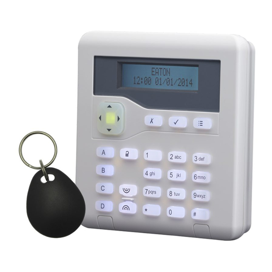
Chapter 1: Introduction to i-on10 The i-on10 control unit is a grade 2, 10-zone control unit for wired detectors and up to four keypads. The control unit has been designed to satisfy the most demanding requirements of alarm-systems professionals for domestic and small commercial applications, and is both easy to install and robust. - Page 7 Introduction to i-on10 Table 1: i-on range feature comparison Feature EN 50131 security grade Max on-board radio zones Max on-board wired zones (See note) Max zones on expanders, keypads, etc. Max wired and radio zones (system wide) RS485 Buses Max bus devices Max on-board radio outputs On-board transistor outputs On-board relay outputs...
-
Page 8: System Bus
Introduction to i-on10 Note 1: The maximum number of wired keypads for i-on10 includes KEY-RKPZ keypads. A KEY-RKPZ is a radio keypad that uses a KEY-RKBS base station wired to the bus. Up to two KEY-RKPZ keypads can connect to the same base station, but this feature cannot be used to increase the total number of keypads beyond the limit shown in Table 1. -
Page 9: Key-Ep External Proximity Tag Reader
Introduction to i-on10 The keypads supported by i-on10 are listed in Table 2. Many of these include a built-in proximity reader, which allows users to set or unset the system using a proximity tag. Note: i-on10 does not support zones and outputs connected to a keypad. Note: Do not install a proximity reader closer than one meter to any other type of proximity reader, otherwise the devices may not work correctly. -
Page 10: Detectors (Zones)
Introduction to i-on10 Detectors (zones) Detectors are the physical devices that detect alarm conditions. A zone is the lowest-level item within the intrusion system that can be set or unset. Detectors supported by i-on10 include: XCELW XCELWPT DETWDT-G2 DET-WDTPT-G2 DET-RSDC Note: Although it is possible to connect detectors in series and therefore to have more than one detector in the same zone, it is not normal practice. - Page 11 Introduction to i-on10 Loudspeakers − The i-on10 and KEY-FKPZ keypad have connections for a loudspeaker, which you may want to use to increase the volume or location of setting and unsetting tones. The loudspeaker must have an impedance of 16 Ohms. You must not connect two loudspeakers in parallel to the same port.
-
Page 12: Chapter 2: Installing And Maintaining I-On10
Chapter 2: Installing and Maintaining i-on10 Planning the installation Choosing the installation locations When planning the installation, consider the following recommendations concerning the locations of where to install the control unit and other devices. Control unit The control unit must be located: ... - Page 13 Installing and Maintaining i-on10 When considering the power drawn, include the control unit's PCB and all peripherals powered by the control unit, including any plug-by communicator, keypads and wired detectors. Table 3 gives a summary of the current consumed by the i-on10 PCBs and popular peripheral devices.
-
Page 14: Detector (Zone) Wiring Types
Installing and Maintaining i-on10 Detector (zone) wiring types Before installation, you need to choose the wiring type (method) to use for any wired detectors: Fully-Supervised Loop (FSL), 4-wire Closed Circuit (CC), or 2-wire CC, as described below. You must use the same wiring type for all wired detectors. You will need to ensure that all detectors are wired correctly and that you select the default wiring type during the initial power-up procedure. -
Page 15: Checking Cable Requirements
Installing and Maintaining i-on10 Doors attribute set (see page 31). The zone must use 4k7 shunt resistors and a 2k2 EOL resistor. Alarm Alarm Tamper Tamper Figure 4. Two detectors per zone (Double Doors) 4-wire CC This uses a separate pair of wires for the alarm and tamper contacts. No end-of-line resistors are used. -
Page 16: Installing The Hardware
Installing and Maintaining i-on10 Cable length and configuration (star or daisy chain) You can connect devices either in daisy chain (serially), or in star (parallel) configuration at the control unit connector (Figure 5). For star configurations, the cable length from control unit to the most distant keypad should be kept short, and should not exceed 100m. -
Page 17: Maintaining The System
Installing and Maintaining i-on10 Maintaining the system After installation, the system should be inspected once or twice per year as follows: Check the control unit for obvious signs of damage to the case or its lid. Check the action of the tamper switch. ... -
Page 18: Chapter 3: Configuring The System − Getting Started
Chapter 3: Configuring the System − Getting Started This chapter explains how to: Use the initial power-up procedure to configure the basic settings of the control unit. Enter and exit the Installer menu. Select options and change settings in the Installer menu. ... - Page 19 Configuring the System − Getting Started Choose the language: You can change the language by pressing one or more times. Press to continue. From this point on, the display operates in the selected language. If you want to change the language later, use Installer menu –...
-
Page 20: Entering The Installer Menu
Configuring the System − Getting Started If the lid of the control unit is open, you will see: 14. If the standby screen is displayed, enter the installer menu (as described in the next section). Otherwise, if the "Panel lid open" message is displayed, press to access the Installer menu. -
Page 21: Saving Changes
Configuring the System − Getting Started Saving Changes Changes are saved only when you leave the Installer menu. If you remove all power before leaving the Installer menu, changes will not be saved. Note that this does not apply if you restore factory defaults; that change takes place immediately. Code Lockouts If you (or any user) enter your code incorrectly or present an unrecognised proximity tag, the display shows the time and date again, gives an error tone and you can try again. -
Page 22: Changing A Setting
Configuring the System − Getting Started The appendix starting on page 69 shows a "menu map", which gives the position of all menus and options in the Installer menu. Changing a Setting To change the setting of an option, you normally follow the same procedure as above by pressing ... -
Page 23: Resetting (Defaulting) The System
Configuring the System − Getting Started This is followed by a list of faults, starting with the first. For example: Either: 1. Press to return to the Installer menu (for example, to rectify an issue that is causing the fault). - Page 24 Configuring the System − Getting Started Remove the lid of the control unit (the tamper must be activated for the procedure to work). Disconnect the battery. Place a jumper across the Kick-Start link. While shorting the Reset Codes link, reconnect the battery and keep the short in place until you see the following: ...
-
Page 25: Chapter 4: Detectors/Devices Menu
Chapter 4: Detectors/Devices Menu This chapter explains the options in the Detector/Device menu. Detectors Program Zones You can program (configure) each zone's behaviour at any time, whether or not a wired detector is connected. When you enter the menu, you will see the current configuration of Zone 0: This is the zone number (0-9). - Page 26 Detectors/Devices Menu Hold Up Alarm – HUA (01) Operating a device programmed as Hold Up Alarm (HUA) will start an alarm whether the system (or part set) is set or unset. The alarm response for HUA (audible, silent or displayed) depends on the options selected by HUA Response (see page 56).
- Page 27 Detectors/Devices Menu seconds. When a user enters a valid access code, the tone stops and the display shows the zone causing the alarm. When the user acknowledges the alert by pressing , the control unit resets the technical alarm ready for the next event. Note that a tamper on a Technical Alarm zone when the system is unset will cause an internal alarm.
- Page 28 Detectors/Devices Menu Exit Terminate ET (18) Use this zone type to terminate setting when the exit mode is Exit Terminate (see page 44). This zone type is designed for a normally-open momentary switch. Note that this zone type is armed during the setting time, but inactive both while the system is set, and while the system is unset.
- Page 29 Detectors/Devices Menu Attributes Table 5 shows the zone attributes and the zone types they apply to. You can assign more than one attribute to a zone. The display shows only the available attributes for the zone type you select. Table 5: Zone attributes available for zone types Zone Attributes Zone Type Not Used...
- Page 30 Detectors/Devices Menu During setting, a brief message is displayed to inform the user that one or more zones are in soak test. Note: If there is an output configured as type Zone Follow for a zone under Soak Test, the control unit will continue to operate the output if the soak test zone is triggered.
-
Page 31: Address Bus Device
Detectors/Devices Menu Inverted On FSL zones, the attribute makes the control unit treat resistances in the 6k9 band as “tamper”, and resistances below the 2k2 band as “alarm”. In 4-wire CC zones the attribute makes the control unit treat open alarm contacts as “no alarm” and closed alarm contacts as “alarm”. -
Page 32: Adding A Keypad
Detectors/Devices Menu Adding a keypad If the keypad you are adding already has an address stored within it, you will need to clear the address before adding it to the bus. You can do this manually by pressing the D and keys while the keypad's tamper switch is open, or by using Delete Keypad (page 35). -
Page 33: Wired Keypads
Detectors/Devices Menu Either: Press to return to the Installer menu to check that all keypads are listed and addressed correctly. Make sure that the keypads are powered up. OR: Press to make the control unit update its internal record of keypads attached to the bus. - Page 34 Detectors/Devices Menu The control unit logs the use of quick-set keys under a quick-set user identity (see page Error! Bookmark not defined.). Loudspeaker volume This option is available for the KEY-FKPZ. Use this option to change the volume of chime, entry, exit, alert, confirmation and other tones from a loudspeaker connected to the keypad.
-
Page 35: Delete Keypad
Detectors/Devices Menu Delete Keypad Always use Delete Keypad when you wish to remove a wired keypad from the bus. Using this option defaults the bus device number stored within the device (making the device safe to add to other systems). Exit the Installer menu to save the change. Note: Remove all power from the system (battery and mains) before disconnecting any keypad from the bus. -
Page 36: Radio Keypads
Detectors/Devices Menu Radio Keypads KEY-RKPZ The KEY-RKPZ is a two-way battery-powered radio keypad, with built-in proximity reader. This keypad uses a KEY-RKBS base station connected to the bus. Address Bus Device This option allows you to add a KEY-RKPZ 2-way radio keypad from another existing keypad. - Page 37 Detectors/Devices Menu To replace a keypad: 1. Select Replace Keypad at another keypad, and choose the keypad to replace. When prompted, confirm the replacement. 2. Pair the replacement keypad with the base station. 3. Select Replace Keypad again, and choose the keypad you replaced (the display shows "Add"...
-
Page 38: Chapter 5: Outputs Menu
Chapter 5: Outputs Menu This chapter explains the options in the Outputs menu. Wired Outputs The Wired Outputs menu provides access to edit the configuration of the three hardwired outputs on the control unit's PCB. Select Panel. The display shows the current configuration for output 1. The bottom line of the display shows the output's output type (by default, "Siren"). - Page 39 Outputs Menu Confirmed Alarm (07) Active when there is a confirmed alarm. Deactivates when the system is reset. The operation of this output type depends on the option selected in System Options – Confirmation – Confirmation Mode (see page 52): A/C Fail (12) Active when mains power is absent.
- Page 40 Outputs Menu PIR Set Latch (25) Active when the system is set. Inactive when the system is unset or an alarm condition occurs. The output is active for one second when a reset is performed or when the control unit leaves installer mode. Note: By default this output is at +12V when active and 0V when inactive.
- Page 41 Outputs Menu Set Fail (38) Active when a set command fails. Remains active until the user acknowledges the set fail. Zone Follow (39) Active when any selected zone is active, irrespective of whether the zone is set or unset. The zones can include Log Only zones. Specify the zones using the Zones option (see page 43).
- Page 42 Outputs Menu Courtesy Light (45) Active when the entry or exit timer is running. The control unit activates this output when the entry or exit time starts, and deactivates the output 10 seconds after the entry or exit time stops. Installer on Site (46) The control unit activates the output when an installer enters the Installer menu, and deactivates the output once the installer has exited the Installer menu.
-
Page 43: Plug-By Outputs
Outputs Menu Alert Active (74) Active when the LEDs around the navigation key on a keypad are red. The control unit deactivates the output when the LEDs go green. Panel Lid Open (75) Active when the control unit lid or back tamper is active. The control unit deactivates the output when the control unit lid or back tamper is inactive. -
Page 44: Chapter 6: Setting Options Menu
Chapter 6: Setting Options Menu The Setting Options menu contains all the options to program entry, exit and alarm response. You can configure different settings for the full-set level and each part-set B/C/D level. Note: The default settings for these options are compliant with EN50131. Changes to some of the defaults may render the system non-compliant. -
Page 45: Settle Time
Setting Options Menu Lock Set Use this setting if you are using a lock to set the system. To use Lock Set, you must: Configure a Lock Set zone (see page 28) that is activated by a suitable lock (located on the final exit door). -
Page 46: Exit Time
Settings Options Menu Exit Time This option is available only if Exit Mode is set to Timed Set or Silent Set. The exit time can take any value between 10s and 120s. Entry Time The entry time can take any value between 10s and 120s. The entry time you select in this option applies to full set and all part sets. -
Page 47: Pt.set Entry Route
Setting Options Menu Final Exit Any zones of type Final Exit with Part Set B, C or D attributes continue to act as Final Exit zones during part setting. Normal Alarm Any zones of type Final Exit with the Part Set B, C or D attributes act as Normal Alarm zones during part setting. -
Page 48: Chapter 7: System Options Menu
Chapter 7: System Options Menu This menu contains options that affect the working of the alarm system as a whole. Note: The default settings for these options are compliant with EN50131. Changes to some of the defaults may render the system non-compliant. User Options User Access Use this option to give users access to various system facilities. -
Page 49: User Reset
System Options Menu Terminated Set (This option is relevant if you are using a KEY-EP external proximity reader connected to a keypad.) Yes – Select this if you want to start the setting procedure from a keypad and complete it at the KEY-EP. You will not be able to start the setting procedure from the KEY-EP. -
Page 50: Keypad Text
System Options Menu Note: Users can reset the system if they unset the system during an alarm, but before the Alarm Abort period has expired (see page 57). Zone Tampers Yes – The user can reset the system after an alarm caused by a zone’s tamper circuits being triggered. -
Page 51: Factory Defaults
System Options Menu If you change from 4-digit to 6-digit codes, two additional zeros are added to the end of the existing installer code. If you change from 6-digit to 4-digit codes, the final two digits are removed from the end of the existing installer code. To comply with EN 50136-2, 6-digit access codes must be configured for access to SPT functions at level 2, 3 and 4. -
Page 52: Installer Timeout
System Options Menu Installer Timeout The installer is automatically logged out of the Installer menu if there is no activity after the specified period. Service Date This option allows you to specify the date when the next maintenance service of the system is due. -
Page 53: Confirmation Time
System Options Menu Confirmed Alarm Output Types The following output types are available: Confirmed Alarm (page 39) – Generated when there is a confirmed alarm. Burg Confirmed Alarm – Generated when any two of the following alarms have activated (in any order) while the system is set (subject to the entry timer not expiring, as described above): Normal Alarm... -
Page 54: Entry Keypad Lock
System Options Menu 1 zone The control unit starts a confirmed alarm if the intruder activates one or more zones (not on the entry route) after entering the premises through the final exit zone. 2 zones The control unit starts a confirmed alarm if an intruder activates two or more zones (not on the entry route) after entering the premises through the final exit zone (used for DD243:2004 clauses 6.4.5) Note: This option is not available if you have selected BS8243 for Confirmation Mode. -
Page 55: Siren On
System Options Menu Unconfirm Confirm Unconfirmed alarm: keypads and loudspeakers sound immediately and run for the Siren Time. Confirmed alarm: the control unit waits for any Siren Delay (see page 46), and then starts the alarm sound at sirens and restarts the sound at all keypads and loudspeakers. -
Page 56: Hua Response
System Options Menu HUA Response This option controls the audible alarm associated with Hold-Up Alarms (HUAs). Note: All HUAs are disabled when an installer is using the Installer menu. HUA Keys Active (page 48) must be enabled to generate HUA alarms from keypads. -
Page 57: Abort Time
System Options Menu Note: If you are using Fast Format communications, please ensure that one channel is allocated for tamper. If you do not do this, the control unit reports tamper as an unconfirmed Burg to ensure the condition is notified. Abort Time Use this option to change Alarm Abort Delay period. -
Page 58: Mains Fail Delay
System Options Menu Mains Fail Delay This option allows you to specify the length of time (0 to 60 minutes) that the control unit must wait after detecting a mains supply failure before reporting Mains Fail to the ARC. When the mains supply fails, the control unit lights the red alert LEDs around the navigation key within a few seconds of the failure, activates any output programmed as General Fault and logs the Mains Fail event (in the mandatory log). -
Page 59: Reset Codes Pins
System Options Menu Reset Codes Pins This option allows you to enable or disable the Reset Codes link on the i-on10 PCB. If you disable Reset Codes Pins, the Reset Codes link cannot be used to reset the installer and master user codes. -
Page 60: Chapter 8: Communications Menu
Chapter 8: Communications Menu Line Fail Response Use this option to specify how the system should respond when the control unit detects a line-fail fault from the plug-by communicator. The control unit monitors for line faults by using the LF input on the plug-by port. The communicator should apply 0V to the LF input if there is no fault, and 12Vdc if a fault is present. -
Page 61: Chapter 9: Test Menu
Chapter 9: Test Menu Sirens and Sounders This option allows you to test the warning devices. Press to turn the device on. Press to turn the device off. The display shows On when the device should be operating and Off when the device should be silent. Wired Sirens This option allows you to operate all outputs of type Siren and Strobe. -
Page 62: Zone Resistances
Test Menu loudspeakers give confirmation tone. The bottom-right corner of the display shows an “A” if you trigger the Alarm input and a “T” if you trigger the Tamper. The top of the display shows the number of zones left to test. The control unit decreases the number of zones every time you trigger an individual Alarm input. -
Page 63: Signal Strengths
Test Menu Signal Strengths Radio Keypads KEY-RKPZ This option allows you check the received signal strength from KEY-RKPZ radio keypads belonging to the system. The display shows first: the strength of the most recent signal it has received from the keypad, and second: (in brackets) the minimum strength signal it has received from the keypadsince the records were last reset. -
Page 64: Chapter 10: View Log Menu
Chapter 10: View Log Menu The control unit keeps a log of events (for example, alarms and times of setting/unsetting). An installer or master user can read the log when the system is completely unset. Note that no other user type can read the log. Log Events To comply with EN50131-1:2006 for grade 2 systems, the log is divided internally into two portions: mandatory events and non-mandatory events. -
Page 65: Chapter 11: About Menu
Chapter 11: About Menu The About menu offers information about the control unit and keypads. Panel This option shows: The control unit model (i-on10). The control unit's name, if defined in System Options, Hardware, Panel Name (page 57). ... -
Page 66: Appendix A: Log Messages
Appendix A: Log Messages Introduction This Appendix gives short explanations of the messages that may appear in the control unit’s log. Please note that many of the messages refer to specific devices by the bus and device number. Therefore, it is not possible to show in this list the exact log message that you may be seeing on any given installation. - Page 67 Log Messages "Entry Stray Z==" Stray on entry alarm at zone n "Lockset Z=== Set" Zone n with type "lock set" was closed (If Inverted attribute is set to "Ext WD Fault Z===" A warning device has reported a "normal") fault through zone n "Lockset Z=== Unset"...
- Page 68 Log Messages "U--- O/P === On" User defined output swittched off "U--- Z=== Omit Rst" User n included Hold Up Alarm by user n zone n "U-- Off-Site" User n left Installer mode "U--- Z=== Omit Rst" User n included (restored) zone n "U-- On-Site"...
-
Page 69: Appendix B: Installer Menu Map
Appendix B: Installer Menu Map Important: The defaults listed below enable the control unit to comply with EN50131 requirements. If you change those settings, the installation may no longer comply. If the control unit does not comply with EN50131, you must remove any labelling that indicates compliance. - Page 70 Installer Menu Map Delete Keypad Enable Keypad Yes (all keypads enabled) Replace Keypad 2 Outputs Panel EDIT output Wired outputs Name Type For outputs 1 and 3, the default "Type" is "Siren". For output 2, the default "Type" is "Strobe". Polarity Normal Latched...
- Page 71 Installer Menu Map Strobe on Set Strobe on Unset 4 System Options User Access HUA keys active User Options Quick set Quick omit User code reqd Duress Enable Terminated Set Used for KEY-EP. Tamper Omit Silence Alerts User Code User Reset Zone alarms Available only if Confirmation Mode is ”Basic”.
- Page 72 Installer Menu Map 6 Communications Plug-by Line Fail Silent Response Plug-by Line Fail Delay 7 Test Wired Sirens Sirens & Loudspeakers Sounders Wired Keypads KEY-RKPZ Wired Keypad KEY-RKPZ Radio Keypads Chime Once Walk Test System Zones Zone Resistances Wired Zones Zone Status Radio Keypads KEY-RKPZ...
- Page 73 Product Support (UK) Tel: +44 (0) 1594 541978 Available between: 08:30 to 17:00 Monday to Friday. email: securitytechsupport@eaton.com Part Number 14199582 Issue 2 24th January 2022 Page 73...
Need help?
Do you have a question about the Scantronic i-on10 and is the answer not in the manual?
Questions and answers
i have yet again tried to programme in a new master user code. it will only allow set or unset. I am a retired alarm engineer but this has got me stumped. have removed power and shorte the pins and repowered but no joy. I can put in new eng code and user 1 which accoring to the manua is mast. Help!!!