
Related Manuals for Eaton i-on style


Summary of Contents for Eaton i-on style
-
Page 1: Security System
Style Security System Engineering Guide Issue 2 Control unit software version 5.01... -
Page 2: About This Guide
CONTENTS OF THIS DOCUMENT SHALL NOT BECOME PART OF OR MODIFY ANY CONTRACT BETWEEN THE PARTIES. In no event will Eaton be responsible to the purchaser or user in contract, in tort (including negligence), strict liability or other-wise for any special, indirect, incidental or consequential damage or loss whatsoever, including but not limited to damage or loss of use of... -
Page 3: Table Of Contents
Contents About this Guide ....................... ii Other Publications ......................ii Chapter 1: Introduction ................1 Introduction to i-on Style control units ................1 System features ....................... 1 About the built-in keypad ....................3 Alarm communications ....................3 About Part-setting and partitioned modes ..............4 About radio and wired outputs .................. - Page 4 On-board Keypad ......................34 Home Key Action ......................34 Hot Key Action ......................35 Audible Keys ....................... 35 Radio Keypads (i-rk01) ....................35 Add/Del Radio Kpd ..................... 36 Edit Keypads ......................36 External Sirens ....................... 37 Add/Del Siren ......................37 Edit Siren ........................
- Page 5 Full Set Link ........................56 Remote Set ........................56 Exit Mode ........................56 Exit Time ........................56 Local Set on ER ......................56 Calendar Set ........................56 Add Event ........................57 Edit Event ........................58 Delete Event ....................... 58 Add Exception ......................58 Edit Exception ......................
- Page 6 Keypad Text ........................70 Remote Needs Entry ...................... 70 Remote Entry Part Set ....................70 RKP Needs Entry ......................70 RKP Entry PrtSt......................71 HUA Response....................... 71 PZ Unset Response ....................... 71 PZ Unset Response ....................... 71 PZ Reset time ........................ 71 Auto Rearm ........................
- Page 7 Messages ........................89 Triggers ........................89 Destinations ........................ 90 Call Acknowledge ....................... 90 SMS ..........................90 Outgoing ........................90 Incoming ........................91 PSTN SMS ......................... 92 Email ..........................92 Call Mode ........................92 Messages ........................92 Triggers ........................92 Destinations ........................ 93 Server .........................
- Page 8 On-board Keypad ......................103 Radio Keypads ......................103 Walk Test ........................104 Zone Resistances ......................104 Signal Strengths ......................105 Outputs ......................... 105 Radio/Wired Outputs ....................105 Remotes ........................106 Pendants ........................106 User HUAs ........................106 Prox Tags ........................106 ARC Reporting ......................
-
Page 9: Chapter 1: Introduction
Chapter 1: Introduction Introduction to i-on Style control units i-on Style is a high-reliability radio alarm system intended for use in domestic and small commercial applications. The system supports up to 40 wireless (radio) detectors and, if required, an additional 4 detectors wired directly to the control unit. - Page 10 Introduction Table 1: System features and limits Feature EN 50131 security grade Max on-board radio zones Max on-board wired zones (Note 1) Max wired and radio zones (system wide) Max on-board radio outputs On-board transistor outputs On-board relay outputs Max custom outputs Max outputs (system wide) (Note 2) Ethernet port USB port...
-
Page 11: About The Built-In Keypad
Automatic timeout from the user menu. Backlit display and keys. Alarm communications An i-on Style control unit can use three different methods to communicate alarm information, as described next. PSTN communications The control unit includes a built-in PSTN (Public Service Telephone Network) communicator, which can be used to: ... -
Page 12: About Part-Setting And Partitioned Modes
GSM network can introduce too great a variation in the delay between signal and response. About Part-setting and partitioned modes An i-on Style control unit offers part-setting and partitioned modes: Part-setting mode In part-setting mode, the control unit can set in one of four ways: either full set or one of three part sets (part set B, C or D). -
Page 13: Control Unit Usb Port
Store images from network cameras (on the SD card). Send emails automatically when events occur. Supported peripheral devices This section provides an introduction to the peripheral devices supported by i-on Style. Detectors (zones) Detectors are the physical devices that detect alarm conditions. A zone is the lowest-level item within the intrusion system that can be set or unset. -
Page 14: Sounders
Introduction 706rEUR-00 10mW tilt switch and personal attack transmitter. 710rEUR-00 Dual-button personal attack transmitter 713rEUR-00 Pet-tolerant PIR 714rEUR-00 XCELR XCELRPT Pet-tolerant PIR DET-RDT Combined microwave and PIR detector range 720rEUR-00 Smoke detector DET-RSMOKE Smoke Detector 726rEUR-50 Long-range hand-held personal attack transmitter 726rEUR-60 Short-range hand-held personal attack transmitter 734rEUR-00... -
Page 15: Cameras
Introduction External radio sirens/strobes Radio siren/strobe units can communicate directly to the control unit using a radio link. The SND-REXT external radio siren/strobe units is supported. Note: It is possible to connect a wired external siren/strobe unit to one of the control unit's outputs. -
Page 16: Chapter 2: Planning The Installation
Chapter 2: Planning the Installation Choosing the installation locations When planning the installation, consider the following recommendations concerning the locations of where to install the control unit and other devices. Note: Also refer to the device installation instructions for any further guidance. General requirements Do not locate any device: ... -
Page 17: Wired Detector (Zone) Wiring Types
Planning the Installation including two 15-minute periods in alarm. This meets the requirements of EN50131-1 or PD6662 Grade 2. When two batteries are used, they are capable of powering the system for at least 24 hours. Output devices or other equipment can be powered from the control unit (see note above), providing you make sure that the power supply has sufficient capacity to do so. -
Page 18: 4-Wire Cc
Planning the Installation Table 2: FSL Resistor Bands (without Masking) Zone State 2k2/4k7 FSL 1k/1k FSL 2k2/2k2 FSL 4k7/4k7 FSL 0k0 – 1k759 0k0 – 1k759 0k0 – 3k759 Tamper 0k0 - 0k799 1k76 – 4k08 Normal 0k8 - 1k4 1k76 - 3k08 3k76 - 6k58 4k081 –... -
Page 19: Chapter 3: Getting Started
Chapter 3: Getting Started Once all wiring is complete, the system is ready to be programmed. This section provides an overview of how to carry out this task. Later sections of this guide explain the configuration options in more detail. About the user interface The control unit displays configuration options in menus. -
Page 20: Initial Power-Up Procedure
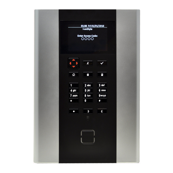
Getting Started example, you can use the "2" key to enter A, B, C and 2 (where applicable). Also use (where applicable): # to change between capital and lower-case letters. 0 to enter a space or other characters such as "&", "@" and "/". When you first select an option to enter text, the display shows the cursor at the beginning of the bottom line. - Page 21 You will see the date and time at the top of the standby screen. For example: 10:15 Fri 01/01/2016 i-on Style-EU 10. Enter the Installer code to enter the Installer menu. 11. Use the Installer menu to carry out the required configuration tasks, such as to: ...
-
Page 22: Entering The Installer Menu
To enter the Installer menu: Make sure the system is fully unset and showing the standby screen. For example: 10:15 Fri 01/01/2016 i-on Style-EU Enter the Installer code, as specified when the control unit was first configured: Enter Access Code: ... -
Page 23: Code Lockouts
The web interface, through a web browser. The i-on Web Browser Interface Setup Guide explains how to configure the system using the web interface. Optionally, you can access the web interface through the Eaton SecureConnect web portal, as described in the SecureConnect Installer’s Guide. -
Page 24: Resetting (Defaulting) The System
Getting Started Resetting (defaulting) the system Restoring control unit factory defaults You can remove all configuration from the control unit using System Options – Restore Defaults – Factory Defaults (see page 69). You must restore defaults from the control unit; you cannot do this from a PC. -
Page 25: Chapter 5: Installer Menu Map
Chapter 5: Installer Menu Map Important: The defaults listed below enable the control unit to comply with EN50131 requirements. If you change those settings, the installation may no longer comply. If the control unit does not comply with EN50131, you must remove any labelling that indicates compliance. - Page 26 Installer Menu Map Add/Del Sounder Internal Edit Sounder Int. SNDR 01... Sounders "Int. SNDR nn" Name Partitions Partition 01 Visible only in a partitioned system. Volume Add/Del WAM WAMs Edit WAM None IP Cam 1... Camera Triggers Cameras Zone Follow Zone Alarm Trigger Partitions All Partitions...
- Page 27 Installer Menu Map Siren Alarm Response 0 minutes Siren Delay 15 minutes Siren Time Pt.set Final Exit Final exit Pt.set Entry Route Entry Route Strobe on Set Strobe on Unset Timed Set Exit Mode Remote Set Exit Time Local Set on ER None Calendar Set Visible only in a partitioned system.
-
Page 28: System Options
Installer Menu Map No for all exceptions Exceptions 10min Warning Time Audible Warning Tone Delete Event Add Exception Exception 01... 00:00 Exception Start Time 01/01 Exception Start Date 00:00 Exception End Time Exception End 01/01 Date Edit Exception Exception 01... "Exception nn"... - Page 29 Installer Menu Map “Installer” Installer Name Installer configured Installer Code Panel name Keypad text Disabled Remote needs Entry Disabled Remote Entry PrtSt Disabled RKP needs Entry Disabled RKP Entry PrtSt Audible Visible only for part-setting system. HUA Response Silent Visible only for part-setting system. PZ Unset Response Silent Visible only for part-setting system.
- Page 30 Installer Menu Map 6 Communications Recipient A Recipient A... Name Contacts Empty Tel No 1 Tel No 2 Empty Email Empty Empty IP Address Single Call Mode Telecoms Priority Panel Ethernet Reporting PSTN Visible only if a GSM module is fitted. Recipients Tel.
- Page 31 Remote Servicing Enable Service Disabled Disabled Serv. On Exit Eng Tel No 1 Service Call Num Visible only for UK systems. Downloader must be enabled by Eaton. 00:00 Time Window Start Time Window End 06:00 Next Service Date 24/12/2015 Page 23...
-
Page 32: View Log
Installer Menu Map 180 days Service Interval Start Service Call 7 Test Ext. Radio Sirens Sirens & On-board Loudspeaker Sounders On-board Sounder Internal Sounders On-board Keypad Radio Keypads Chime Once Walk Test System Partition Zones Visible only is systems that have wired Zone Resistances zones. -
Page 33: Chapter 6: Detectors/Devices Menu
Chapter 6: Detectors/Devices Menu This chapter explains the options in the Detector/Device menu. Detectors Add/Del Detectors This option allows you to add and delete radio detectors (zones). Adding radio detectors To add a radio detector: Select a zone. to the right of a zone name indicates that the control unit has learned a radio detector for that zone. - Page 34 Detectors/Devices Menu Name You can give each zone a 12-character name. The control unit displays this name when, for example, you select the zone or the zone generates an alarm. Type The list below shows the available zone types. Note: ...
- Page 35 Detectors/Devices Menu 24 Hour Alarm - 24 (04) Activating this zone while the system (or partition) is unset causes an internal alarm (internal sounders only). Activating this zone while the system (or partition) is set causes an alarm from internal and external sounders. Final Exit –...
- Page 36 Detectors/Devices Menu Note: The keyswitch zone types are intended for use on zones that connect to an access-control keypad, electronic key or other type of hardwired device used to set or unset the system. When the user operates the keyswitch while the system is unset, the control unit starts the programmed exit mode.
- Page 37 Detectors/Devices Menu External WD Fault – WD (15) Use this zone type to monitor the fault output of an external warning device. If a warning device triggers a zone with this type, the control unit generates an “Ext WD Fault” alert. A user can override this fault and set the system.
- Page 38 Detectors/Devices Menu In a system with partitions, the behaviour of a Shunt Key Latching zone is limited by the partitions that the zone belongs to as follows: If the zone is allocated to one or more partitions, then when a user activates the zone, the control unit shunts only zones with the Shuntable attribute in the same partition(s) as the Shunt Key Latching zone.
- Page 39 Detectors/Devices Menu Perimeter PZ (25) This zone type intended to be used with external (perimeter) detection equipment. PZ Unset Response (see page 52) and PZ Set Response (page 53) determine the response to activations of the zone. A Perimeter zone or the zone's tamper does not contribute to a burg or confirmed alarm.
- Page 40 Detectors/Devices Menu Table 4: Zone attributes available for zone types Zone Attributes Zone Type Not Used Hold Up Alarm Fire Alarm Normal Alarm 24 Hour Alarm Final Exit Entry Route Technical Alarm Key Switch Moment. Key Switch Latched Tamper Ext PSU AC fail Ext PSU Batt Fault Ext PSU Low Volts Ext PSU Fault...
- Page 41 Detectors/Devices Menu whole fourteen days then after midnight on the 14th day, the control unit returns the zone to normal use. If the zone is activated during those 14 days while the system is set, the control unit logs the event as a “Soak Fail Znn Alm” (nn is the zone number) without sounding any sirens or starting communications.
-
Page 42: On-Board Keypad
Detectors/Devices Menu Masking Apply this attribute either if you have connected a detector that reports masking by changing the resistance between its mask/fault contacts, or if you have connected the masking/trouble contacts of a detector using the “3 resistor method” (see the installation instructions). -
Page 43: Hot Key Action
Detectors/Devices Menu The key will sets the system in a specified way (such as to full set partition 1 and part set partition 2). Select Set, and then choose what and how you want the system to set. In a part-setting system, you can configure the Home key to one of: Full Set, Part Set B, Part Set C or Part Set D. -
Page 44: Add/Del Radio Kpd
Detectors/Devices Menu If the jumper is fitted, the radio keypad transmits an unset command two seconds after the user presents a recognised proximity tag. This feature is designed for use when the keypad is working with BS8243/DD243 compliant systems. (Note that this delay does not apply to the setting procedure.) If the Jumper is not fitted, the keypad transmits a command after a user has presented their proximity tag, and then pressed another key (A, B, or unset). -
Page 45: External Sirens
Detectors/Devices Menu Partition 1, B = = Full Set Partition 2, C = Full Set Partition 3, D = Full Set Partition Note: The partition(s) that the keypad is allocated to does not influence the configuration of the quick-set keys. A user will be able to set any partition that the user is allowed to set. -
Page 46: Internal Sounders
Detectors/Devices Menu Internal Sounders This menu allows you to add, delete and edit internal radio sounders. See Table 1 on page 2 for the maximum number of internal radio sounders per control unit. Add/Del Sounder To add or remove an internal radio sounder, select Add/Del Sounder, then choose one of the sounder numbers (names). -
Page 47: Ip Cam 1
Detectors/Devices Menu IP Cam 1... Select the camera you wish to configure. The following options are available for each camera: Camera Triggers Select the events that are to trigger images to be saved from the camera. For example, if you select Yes for Fire Alarm, the control unit will save images from the camera whenever a fire alarm occurs. -
Page 48: Chapter 7: Outputs Menu
Chapter 7: Outputs Menu This chapter explains the options in the Outputs menu. Radio Outputs Add Outputs To use a radio output, you must use this option to teach the identity of the receiver to the control unit. Note: If you are teaching 762r or 768r receivers, make sure that you disable IR learn on the receivers first. - Page 49 Outputs Menu Technical Alarm (06) Active when there is a technical alarm. Deactivates when the zone causing the alarm is restored AND a user enters a valid access code to acknowledge the technical alarm alert. Confirmed Alarm (07) Active when there is a confirmed alarm. Deactivates when the system is reset. The operation of this output type depends on the option selected in System Options –...
- Page 50 Outputs Menu Zone Omit (Setting) (17) Active when the user omits a zone while setting the system. The output deactivates when the control unit restores the zone. Zone Omit (System) (18) In the event of an unconfirmed alarm, the system will rearm itself when the confirmation timer expires.
- Page 51 Outputs Menu Smoke Sensor Reset (28) This output is active (0V) all the time except when a user acknowledges a fire alarm. After which, the control unit deactivates the output for three seconds. This output type is designed to be connected to low-voltage smoke detector reset terminals. Note: Some smoke detectors (for example the Texecom OH 4W) require that the user reset the system twice after an alarm.
- Page 52 Outputs Menu belongs to must be set. If a partition is part set, the zone must belong to the part set that the user has selected The output deactivates when the alarm is reset. Specify the zones using the Zones option (see page 47).
- Page 53 Outputs Menu Installer on Site (46) The control unit activates the output when an installer enters the Installer menu, and deactivates the output once the installer has exited the Installer menu. Duress Code (47) Active when a user keys in a Duress code, and deactivates the output when a user or engineer resets the system.
- Page 54 Outputs Menu Perimeter (55) Activates when a zone of type Perimeter is activated. Deactivates when the system is reset by a user. Perimeter Timer (56) Activates when a zone of type Perimeter is activated. Deactivates at the end of the period specified by PZ Reset Time (page 53) or when the system is reset by a user, whichever occurs first.
-
Page 55: Wired Outputs
Outputs Menu Pulsed This option is available for some output types. Selecting Yes causes the output, when activated, to give a single pulse of a specified length after a specified delay. See Delay and On Time below. If Pulsed is set to No, the output changes state when the zone changes state. -
Page 56: Example
Outputs Menu Note: An input can be the output of another custom output. However, you can select only custom outputs of higher number as the custom output you are defining. For example, if you are defining Custom Output 2, it can use only the outputs of Custom Output 3 and Custom Output 4 as inputs. -
Page 57: Chapter 8: Setting Options And Partitions Menus
Chapter 8: Setting Options and Partitions Menus About these menus If you are using a part-setting system, the Installer menu contains a Setting Options menu, which contains all the options to program entry, exit and alarm response for a single alarm system with a full-set and three part-set levels. - Page 58 Settings Options and Partitions Menus a PIR may still be in lockout, during which it cannot send a signal to complete the setting process. Instant Set The system sets immediately and without any setting tone. The control unit and internal radio sounders give confirmation tone when the system is set. Note: This option does not comply with BS8243:2010.
-
Page 59: Settle Time
Settings Options and Partitions Menus Settle Time This option is available only if Exit Mode is set to Final Door Set, Lock Set or Exit Terminate. This option allows you to define a time delay to allow detectors to settle before the system sets. -
Page 60: Pz Unset Response
Settings Options and Partitions Menus Note: All HUAs are disabled when an installer is using the Installer menu. In a partitioned system, HUA Response applies to both a full-set or part-set partition. For a part-setting system, this option appears in System Options. PZ Unset Response Specifies the system response for activations of zones of type Perimeter in the unset state. -
Page 61: Pz Set Response
Settings Options and Partitions Menus PZ Set Response Specifies the system response for activations of zones of type Perimeter in the set state. In a partitioned system, each partition can have different response. In a part-setting system, this option applies to the complete system. Note: For a part-setting system, this option appears in System Options. -
Page 62: Siren Delay
Settings Options and Partitions Menus Siren Delay When the system (or partition) is set and (for example) a zone is activated, the system waits for the programmed Siren Delay before operating the siren and internal sounders. The system then operates the siren and internal sounders for the programmed Siren Time. Note: ... -
Page 63: Part Set Exit Mode
Settings Options and Partitions Menus Part Set Exit Mode Pt.set Settle Time Part Set Exit Time Pt.set Entry Time Pt.set Alarm Resp. Pt.set Siren Delay Pt.set Siren Time These options control system behaviour when the system is part set. Please refer to the equivalent full-set options described above. -
Page 64: Full Set Link
Settings Options and Partitions Menus Full Set Link Some commercial premises include two or more separate areas linked by a common area such as a lobby. The Full Set Link option, which is available on partitioned systems, enables you to configure the system so that the common area sets automatically when the last occupant leaves the premises. -
Page 65: Add Event
Settings Options and Partitions Menus If you create an event to unset a partition, and another event to set the same partition again, you must program the setting event to occur at least 10 minutes after the unsetting event. ... -
Page 66: Edit Event
Settings Options and Partitions Menus At the end of the period, the control unit stops the warning tone, sets the affected partition(s) without any delay and deactivates any outputs of type Autoset Warning. Warning Tone Press or to choose between Audible or Silent. When Silent, the control unit will NOT sound a warning tone for the event (although the warning timer will still operate). -
Page 67: Setting Faults
Settings Options and Partitions Menus Press the Menu key to gain access to the setting menu to set another partition that is not involved in the current setting event. Note that if the user is allocated to a single partition, that partition may start setting immediately. If a user defers a setting event, the control unit halts the warning timer, and defers setting 30 minutes from the start of the warning time. -
Page 68: Chapter 9: System Options Menu
Chapter 9: System Options Menu This menu contains options that affect the working of the alarm system as a whole. Note: The default settings for these options are compliant with EN50131, see page 17. Changes to some of the defaults may render the system non-compliant. Wired Zone Type This option lets you change the zone wiring type for the control unit. -
Page 69: Quick Omit
System Options Menu Quick Omit Yes – Allows users to omit a zone that is active while the user is setting the system. The zone must have the Omittable attribute (see page 31). No – Users must use the Omit menu to omit a zone that is active before they can set the system. -
Page 70: Zone Tampers
System Options Menu Yes – The user can reset the system after an alarm triggered by a zone’s alarm circuit. No – The installer must reset the system after an alarm triggered by a zone’s alarm circuit. See also CSID Code on page 74. Note: Users can reset the system if they unset the system during an alarm, but before the Alarm Abort period has expired (see page 72). -
Page 71: Confirmation Time
System Options Menu If the first ("unconfirmed") alarm is caused by the expiry of the entry timer, then for: DD243 – A further two zones that are not on the entry route must be triggered to activate the output. ... -
Page 72: Sounder On
System Options Menu The user can enter an access code after the entry door opens (used for DD243:2004 clause 6.4.4). The user must unset the system by some means other than entering an access code, such as a proximity tag, remote control or key switch (used for DD243:2004 clause 6.4.5 and BS8243:2010 6.4.5b). -
Page 73: Siren On
System Options Menu Siren On Unconfirm The control unit operates the siren for all alarms (and overrides any Siren Delay). Confirm When the system is set, the control unit does not activate the siren(s) until a confirmed alarm occurs. The behaviour of internal sounders and external sirens is described in Table 5. Unconfirmed Reset This is available for only for UK control units and when Confirmation Mode is set to DD243 or BS8243. -
Page 74: Tamper As Tamper Only
ARCs. Enabled When an unconfirmed tamper occurs, the control unit sends only “Tamper” to the ARC and activates any output configured as type Tamper (this follows Eaton’s understanding that BS8243, Annex H.7.1 applies to all Grades). Disabled When an unconfirmed Tamper occurs, the control unit sends “Tamper”, “General... -
Page 75: Alarm Response When The System Is Set
System Options Menu events occurring within three seconds of each other may prolong the delay up to 10 seconds (but no longer). Alarm response when the system is set Detector output Response Mask The control unit treats a masking event as an alarm condition (Alarm open, (and also activates any output of type Masking). -
Page 76: Shunt Groups
System Options Menu Shunt Groups Use this menu to allow users to shunt groups of zones. First, make sure that all the zones you wish users to be able to shunt have the Shuntable zone attribute (see page 34). Select the shunt group to edit, and then specify the zones you want to include in that shunt group. -
Page 77: Factory Defaults
System Options Menu Radio Devices Deletes the IDs for learned radio devices. Scroll through the list of devices and select Yes for each type you want to delete, then press to action your selection. The Keypads option deletes one-way radio keypads. Outputs Defaults all output configuration. -
Page 78: Keypad Text
System Options Menu Keypad Text This allows you to specify the text that appears on the first line of the display in the standby screen (such as your company name). See page 11 for editing text. Remote Needs Entry This option relates to the use of remote controls when unsetting a full-set system or full-set partition. -
Page 79: Rkp Entry Prtst
System Options Menu RKP Entry PrtSt This option relates to the use of one-way radio keypads when unsetting a part-set system or part-set partition. Enabled The user must first trigger a Final Exit zone and start the entry timer before unsetting a part-set system or partition with a radio keypad. -
Page 80: Partitions
System Options Menu Note: This does NOT change the volume of sound from the built-in loudspeaker (e.g. used to replay speech memos). Use System Config – Volume Settings in the User menu to set the volume of the loudspeaker. Partitions In a partitioned system, you can assign the control unit's internal sounder to any of the partitions. -
Page 81: Jamming
System Options Menu Tamper With system set or unset, the control unit starts a tamper alarm and notifies the ARC with a “Supervision” message. If Tamper as Tamper Only is set to Disabled (page 66), any outputs of type RF Supervision or RF Fault activate. -
Page 82: Tamper Omit
System Options Menu when a remote user tries to set the system, the control unit will temporarily ignore the remote user. Tamper Omit If a user omits a zone, it may be necessary also to omit the tamper belonging to that zone. Enabled The tamper is omitted when a user omits a zone. -
Page 83: A/C Fail Reporting
System Options Menu A/C Fail Reporting This determines how the control unit monitors the AC mains supply input. The mains supply is monitored. A loss of supply is reported according to Mains Fail Delay, as described next. The mains supply is not monitored. Mains Fail Delay This option allows you to specify the length of time (0 to 60 minutes) that the control unit must wait after detecting a mains supply failure before reporting Mains Fail to the ARC. - Page 84 System Options Menu mains fail to the ARC. If the mains failures do not overlap, and are both individually shorter than the Mains Fail Delay period, the control unit logs the events and activates any General Fault outputs, but will not send a report to the ARC. If the external PSU is allocated to a partition, and mains power at the external PSU is off for longer than the Mains Fail Delay period, the report to the ARC can show that the partition experienced a mains fail.
-
Page 85: Ext Dc Fail Reporting
System Options Menu Ext DC Fail Reporting This determines how the control unit monitors the DC supply input. The DC supply is monitored. A loss of supply is reported according to Ext DC Fail Delay, as described next. The DC supply is not monitored. Ext DC Fail Delay This option allows you to specify the length of time (0 to 60 minutes) that the control unit must wait after detecting a DC supply failure before generating an alert tone and reporting... -
Page 86: Set Time & Date
System Options Menu Set Time & Date This option lets you set the control unit’s internal clock to the correct time and date. If you are not using an SNTP server (see below), you will have to re-program the date and time if the control unit loses power for an extended time and the battery is exhausted. -
Page 87: Sd Card
System Options Menu Note: The upgrade may default the control unit's configuration settings. Before using Panel Upgrade, it is recommended that you back up the system configuration using the Downloader software or the web interface. Note: If you need to update both the language files and firmware, make sure you update the language files first. -
Page 88: Chapter 10: Communications Menu
Note: For communication to an ARC over Ethernet, currently, only SIA is supported (within a SIA-IP wrapper), developed to SIA DC-09-2013. Before using SIA-IP, please check that your ARC supports it. If not, please advise them to contact Eaton for assistance. Page 80... -
Page 89: Recipients
Note: Eaton does not recommend using the optional GSM module for Fast Format communications. The GSM network introduces too great a variation in the delay between signal and response. Tests carried out by Eaton show that different cell towers from the same providers give different results. - Page 90 Communications Menu If you selected Fast Format in Report Type, you can use Fast Fmt Channels to allocate an event to each of eight channels. Table 6 shows the default events for each channel. Table 7 and Table 8 show the events available. You can key-in the two-digit numbers shown next to each event in order to display that event type.
-
Page 91: Cid/Sia Events
Communications Menu 11. Mains Fail (see note 5) 24. Perimeter Alarm 12. Tamper (see note 6) 25. Burg Alarm P1 (partitioned system only) .. up to the maximum number of partitions Notes: Open and Close provide the same functions as Open/Close, but on two separate channels. - Page 92 Communications Menu Burg and Burg restore Burglar Alarm Burg-Perimeter and Burg-Perimeter restore Burglar Alarm Panel Lid tamper and restore Tampers Detector tamper and restore Bell tamper and restore Radio keypad tamper and restore External siren tamper and restore WAM tamper and restore Alarm confirmation Burglar Alarm Technical alarm and restore...
- Page 93 Communications Menu Exit timeout and restore Exit Timeout Four wrong user codes (also called “User code tamper” Tampers or “excess keys”) User/system zone omit. Zone omit restore. Omit Bypass (shunt) Omit Time and date reset Time Date Reset Installer mode start keypad (web) Installer Mode Installer mode end keypad (web) Installer Mode...
-
Page 94: Restorals
Communications Menu User a changed user b’s code User Code Change User a deleted user b User codes defaulted LB (RB) Installer mode start keypad (web) Installer Mode LR, LT Comms line fault and restore Faults LS (RS) Installer mode end keypad (web) Installer Mode System or partition reset Reset... -
Page 95: Burg Comms Rearm
Communications Menu You can enable or disable restoral reporting using this option. Burg Comms Rearm (This menu appears only if you select “Fast Format” in Communications – Report Type. AND if System Options – Confirmation – Confirmation Mode is set to “Basic”.) This menu option determines what the control unit does with the “Burg”... -
Page 96: Unset Comms
Communications Menu To make test calls at a set time every day select Daily, then select a number between 01 and 24 to choose the time of day for the call. For example, select 18 to program the control unit to make a static test call at 6:00pm every day. To make test calls on the same day every week, select Weekly, then select the day of the week on which the call should take place. -
Page 97: Call Mode
Communications Menu Table 11: Speech Dialler Commands Function Listen – silence any internal sounders and activate the on-board microphone to hear any noise within the range of the microphone. The control unit automatically switches to listen mode after the message has been played six times Speak –... -
Page 98: Destinations
Communications Menu Soak Test Fail (see page 32) Medical Alarm (see page 46) Social Emergency (see page 46) Social Inactivity (see page 101) Destinations Use this option to specify the recipients of the messages: Select a Message 1-4. Select one of the four recipients. Each Message 1-4 can have up to four recipients. Select a contact from the Contacts List (page 80), then one of the two telephone numbers defined for that contact. -
Page 99: Incoming
Communications Menu Messages Specify the text for the Home Message and for the additional four messages (Message 1- 4). The Home Message can have up to 12 characters. Message 1-4 can have up to 30 characters. Triggers For each Message 1-4, specify the event categories that you want to associate with the message. -
Page 100: Pstn Sms
Communications Menu PSTN SMS If you are sending SMS messages by way of the PSTN line, you must program some extra information under this menu. Protocol This option allows you to select the protocol used by the Service Centre. Service Centre Tel No The option allows you to store the Service Centre’s telephone number. -
Page 101: Destinations
If the system is set, the control unit logs the event but does not give any tone or display. The control unit cancels any programmed siren delay if the line is out of order when an alarm occurs. Note: Eaton recommends audible response for line fault. Page 93... -
Page 102: Line Fail Delay
Communications Menu Silent If the system is unset, the display indicates a telephone line fault, the LEDs around the navigation key glow red, and the control unit logs the event. The system may be set again with the line fault present. If the system is set, the control unit does not give any indication or tone but does log the event. -
Page 103: M2M Interface
This is the port that the control unit uses for the interface. The default is 1895. Cloud Access This allows you to make the control unit accessible through Eaton SecureConnect. If you set the option to Enabled, you are prompted to specify the Cloud ID (as specified in the SecureConnect web portal) and Site ID (the name you want to give this control unit). -
Page 104: Downloading
Communications Menu To use this feature, you must first ensure that an account is available on the DDNS server that the control unit can use. Status Set to Enabled to enable the interface. Provider Choose the DDNS provider: no-ip, dyn or ChangeIP. Hostname Specify your hostname, as supplied by the DDNS provider. -
Page 105: Account
Communications Menu Account As part of ensuring the security of a connection, Downloader must uses a separate account name and serial number for each control unit. You can set up the account name and serial number at the control unit using this option. Note: On the first connection, Downloader records the account name and serial number set up at the control unit. -
Page 106: Access Mode
Communications Menu Access Mode This function specifies the method to use to start communications over a telephone line or IP network from a remote PC running Downloader. For an IP connection, select the Unattended setting. Call Out Only Someone must start a call to the remote PC manually from within User Menu (select User Menu –... -
Page 107: Secure Callback
Communications Menu This option also presents another two sub-options where you can key in the port numbers that Downloader “listens” to on the remote PC for the primary and secondary IP addresses. Secure Callback Select this option to allow Downloader to use a third callback number (independent of the telephone numbers in the Downloading –... - Page 108 Communications Menu Service Interval The number of days between each remote service. Start Service Call Select: Remote Service – To start an immediate remote service. The control unit connects to Downloader and uploads the current configuration. Downloader then generates a Remote Service Report and disconnects. ...
-
Page 109: Chapter 11: Social Care Menu
Chapter 11: Social Care Menu This menu allows you to configure: Social-care activity monitoring. Responses to social-care alerts and medical alarms. Start Monitoring Hour Specify the time that you want social-care activity monitoring to start each day. The system monitors all zones that have the Activity Mon attribute, and generates a Social Care alert if no zone triggers at least once every Monitoring Interval within the times specified by Start Monitoring Interval and End Monitoring Interval each day. -
Page 110: Medical Alarm Response
Communications Menu Medical Alarm Response This determines the response to a Medical alarm. Silent The control unit keeps the alarm silent: there are no alarm tones. The control unit signals the alarm using the communications device(s) and activates any outputs of type Medical Alarm. -
Page 111: Chapter 12: Test Menu
Chapter 12: Test Menu Sirens and Sounders This option allows you to test all the warning devices connected to the control unit. For most options, you can choose to operate all warning devices assigned to a specific partition, or all warning devices of the type selected. Press ... -
Page 112: Walk Test
Test Menu b) Press both keys of the two-button HUA. The display shows “Hold Up Alarm Key”. c) Press the Unset key. The display shows “System Unset Key”. d) Test all the numeric keys four at a time (six at a time if using six-digit codes) remembering to press A after each group of four (or six). -
Page 113: Signal Strengths
Test Menu The end of the line shows the resistance of the zone. For 4-wire CC zones, the display alternates between the Alarm resistance (“A”) and the Tamper resistance (“T”). “O/C” means Open Circuit. “0k00” means zero resistance or closed circuit. Signal Strengths This option allows you check the received signal strength from all the radio transmitters belonging to the system. -
Page 114: Remotes
Test Menu Remotes This allows you to test a user’s remote control. The display shows a message prompting you to press any button on the remote you wish to test. Press one of the remote’s buttons. The first line of the display shows the remote’s identity, the button you pressed (“S”... -
Page 115: Speech Dialler
Test Menu Speech Dialler This option allows you to send a test speech call to any telephone number (not just the ones programmed to receive speech messages in the event of an alarm). The display shows a message prompting you to key in a telephone number. Enter the telephone number of the phone that you wish to receive the test message, then press . -
Page 116: Chapter 13: View Log Menu
Chapter 13: View Log Menu The control unit keeps a log of events (for example, alarms and times of setting/unsetting). An installer or master user can read the log when the system is completely unset. Note that no other user type can read the log. Mandatory and Non-Mandatory Log Events To comply with EN50131-1:2006 for Grade 2, the log is divided internally into two portions: mandatory events and non-mandatory events. -
Page 117: Downloader And The Log
Test Menu Downloader – displayed when the downloader carries out an User 046 action. User 047 Virtual Keypad - displayed when the Virtual Keypad carries out an action. User 050 SMS control - displayed when the SMS control carries out an action. -
Page 118: Chapter 14: About Menu
Panel This option shows: The control unit model (i-on Style). The control unit’s software (firmware) version number. The installed languages and their versions. Whether the control unit is configured for partitioned or part-setting mode. -
Page 119: Gsm
Test Menu DNS IP Address This is the IP address of the DNS server used by the control unit. MAC Address This is the unique MAC address of the control unit PCB. Each control unit PCB will have an individual MAC address. For a GSM module, this provides: ... -
Page 120: Appendix A: Arc Communication Formats
Appendix A: ARC Communication Formats Fast Format Fast Format is the format most widely used in the UK. When using the Fast Format, each message transmitted to the ARC consists of the following: A 4,5 or 6-digit account number. 8 channels of data. Each channel communicates the status of an output, as programmed using the ”Fast Format Channels”... -
Page 121: Sia 1, Sia 2, Sia 3 And Extended Sia 3
ARC Communication Formats SIA 1, SIA 2, SIA 3 and Extended SIA 3 When using the SIA formats, the control unit transmits data from the event log to the ARC. The four SIA formats differ in the amount of data transmitted with each message: Type Format SIA1:... -
Page 122: Appendix B: System Maintenance
Appendix B: System Maintenance Inspections The system should be inspected at least once per year. At each inspection: Check the control unit for obvious signs of damage to the case or its lid. Check the action of the tamper switch. ... -
Page 123: Appendix C: Log Messages
Introduction This Appendix gives short explanations of the messages that may appear in the control unit’s log. This appendix includes general i-on messages; i-on Style can produce a subset of the messages listed here. The list itself is sorted alphabetically by the text of the message. In the column “Event Log Text”... - Page 124 Log Messages All Comms Pths Flt All communications paths have a Defaults Loaded The control unit was returned to fault. factory defaults. All Comms Pths Rst All communications path faults Disabled == Keypad disabled. restored. Downloader Lockout Downloader locked out for 30 mins Alm Conf Bus# Tamp Not used.
- Page 125 Log Messages HUA Confirm == Hold Up Alarm confirmed on ISN== Tamper Tamper on Internal Radio Sounder keypad HUA keys. HUA Confirm Aux # Hold Up Alarm confirmed by open Jamming == Rstr Jamming ceased. circuit on AUX Tamp terminals on Jamming == Jamming detected.
- Page 126 Log Messages Ptn # Remote Rst User reset partition remotely. Sec Comms Path Rst Secondary communications path fault restored. Remote Reset User reset system remotely. Set Fail Z== Setting failed at zone. Remote U-- Low Bat Remote control belonging to user has low battery.
-
Page 127: Email Error Messages
Log Messages U-- On-Site (Web) User nn logged into Installer Menu WAM== PSU Restore WAM low power supply restored. from web server. WAM== RF OK WAM supervision OK. U-- On-Site User nn entered Installer mode. WAM== RF Warning WAM about to fail supervision. U-- Ptn # Override User nn overrode set fail at WAM== Sndr Tamper... -
Page 128: Tcp/Ip Error Messages
Log Messages <domain> service not available, closing transmission channel A password transition is needed Requested mail action not taken: mailbox unavailable Requested action aborted: error in processing Requested action not taken: insufficient system storage No mail TLS not available due to temporary reason. Encryption required for requested authentication mechanism Server unable to accommodate parameters Unable to queue message for node... -
Page 129: Overview Of The Ssl-Relevant Messages
Log Messages 1006 Connection is closed or aborted 1007 Socket is locked in RTX environment 1008 Socket, Host Resolver timeout 1009 Host Name resolving in progress 1010 Host Name not existing Overview of the SSL-relevant messages The following table shows SSL-relevant messages that are used in the SSL stack: 10064 Failed to get an IP address for the given hostname 10066... - Page 130 Log Messages 40464 An unexpected message was received from our peer 40592 A fatal alert message was received from our peer 40720 Verification of our peer failed 40848 The peer notified us that the connection is going to be closed 40976 Processing of the ClientHello handshake message failed 41104...
- Page 131 SecureConnect is a trademark of Eaton www.touchpoint-online.com Product Support (UK) Tel: +44 (0) 1594 541978 Available between: 08:30 to 17:00 Monday to Friday. email: securitytechsupport@eaton.com Part Number 12838020 17th February 2017 Page 123...
Need help?
Do you have a question about the i-on style and is the answer not in the manual?
Questions and answers