Axis 2N LiftIP User Manual
Communicator for lifts
Hide thumbs
Also See for 2N LiftIP:
- Configuration manual (128 pages) ,
- User manual (112 pages) ,
- Installation manual (78 pages)
Table of Contents
Advertisement
Quick Links
Advertisement
Chapters
Table of Contents

Subscribe to Our Youtube Channel
Related Manuals for Axis 2N LiftIP


Summary of Contents for Axis 2N LiftIP
- Page 1 ® 2N LiftIP Communicator for lifts User Manual Version: 2.6.0 www.2n.cz...
- Page 2 The 2N TELEKOMUNIKACE a.s. is a Czech manufacturer and supplier of telecommunications equipment. The product family developed by 2N TELEKOMUNIKACE a.s. includes GSM gateways, private branch exchanges (PBX), and door and lift communicators. 2N TELEKOMUNIKACE a.s. has been ranked among the Czech top companies for years and represented a symbol of stability and prosperity on the telecommunications market for almost two decades.
-
Page 3: Table Of Contents
Content: 1. Product Introduction 1.1 Product Description 1.2 Components and Associated Products 1.3 Upgrade 1.4 Terms and Symbols 2. Description and Installation 2.1 Product Description 2.2 Before You Start 2.3 Mounting 2.4 Connection 2.5 Description of LEDs, Terminals, Jumpers and Connectors 2.6 System Voice Menu 2.7 Voice Alarm Station 2.8 IO Extender... - Page 4 5. Service Tool 5.1 Installation and Login 5.2 Introduction to Application 5.3 Use 6. Technical Parameters 7. Supplementary Information 7.1 Troubleshooting 7.2 List of Terms and Abbreviations 7.3 Directives, Laws and Regulations 7.4 General Instructions and Cautions 2N TELEKOMUNIKACE a.s., www.2n.cz 4/117...
-
Page 5: Product Introduction
1. Product Introduction ® In this section, we introduce the Lift1IP product, outline its application options and highlight the advantages following from its use. Here is what you can find in this section: 1.1 Product Description 1.2 Components and Associated Products 1.3 Upgrade 1.4 Terms and Symbols Caution... -
Page 6: Product Description
1.1 Product Description Basic Features ® 2N LiftIP is primarily designed for sites where a LAN is available. ® LiftIP is a Speakerphone on principle. This means that a microphone and a speaker built-in behind the lift button panel are used for bidirectional communication. -
Page 7: Components And Associated Products
1.2 Components and Associated Products Basic Unit – Universal Design These units are installed behind the lift panel, which is prepared for installation in advance. Part No., Name Description 920640 EN basic module ® automatic dialling of up to 6 numbers LiftIP –... - Page 8 Extending Modules – External ® LiftIP I/O Extender Part No., Name Popis 920623E ® The IO extender helps you extend LiftIP with 1 input and 2 ® LiftIP I/O outputs. Extender 2N Voice Alarm Station – Audio Unit 2N TELEKOMUNIKACE a.s., www.2n.cz 8/117...
- Page 9 2N Voice Alarm Station – Switch Part No., Name Description 913660E Audio unit to be installed on the cabin roof and under the cabin 2N Voice Alarm Station – Audio Unit 913661E Audio unit – Lift 1 interconnecting switch 2N Voice Alarm Station –...
- Page 10 Associated 2N Products 918xxx 2N ® Lift8 system: Up to 8 lift connectivity Cabin, shaft and machine room audio units In-built backup rechargeable battery Easy control and configuration – voice menu Check call function Lift blocking option during connection error Internal communication –...
- Page 11 9159014 – 2N ® 2Wire Analogue 2-wire cables can be used for IP intercom connection including PoE supply. Cooperating 2N ® Applications 918700E 2N ® Lift8 Control Panel ® Lift8 Control Panel ® Control Panel application is designed for management of users, lifts and rights.
- Page 12 918700E 2N ® Lift8 Communicator ® Lift8 Communicator ® Lift8 Communicator is designed for receiving alarm calls by the control centre. 918700E 2N ® Lift8 Server ® Lift8 Server 2N TELEKOMUNIKACE a.s., www.2n.cz 12/117...
- Page 13 ® Lift8 Server application processes check calls and mediates communication between the Central Units and PC applications. 2N TELEKOMUNIKACE a.s., www.2n.cz 13/117...
-
Page 14: Upgrade
1.3 Upgrade The manufacturer reserves the right to modify the product in order to improve its qualities. Manual Description of changes version First product/manual version Direct SIP (calling without Proxy server) Events (jammed button, rescue end, audio error) IP camera and video call support (H.264) Protocol logs (SIP, RTSP) IO extender Voice Alarm Station... - Page 15 Caution The manufacturer keeps upgrading the software according to the ® customers‘ needs. The latest firmware version for the LiftIP software and the User Manual are available at www.2n.cz ® Refer to the Service Tool section for the LiftIP firmware upgrade details.
-
Page 16: Terms And Symbols
1.4 Terms and Symbols The following symbols and pictograms are used in the manual: Safety Always abide by this information to prevent persons from injury. Warning Always abide by this information to prevent damage to the device. Caution Important information for system functionality. Useful information for quick and efficient functionality. -
Page 17: Description And Installation
2. Description and Installation ® In this section, we describe the LiftIP product and its installation. Here is what you can find in this section: 2.1 Product Description 2.2 Before You Start 2.3 Mounting 2.4 Connection 2.5 Description of LEDs, Terminals, Jumpers and Connectors 2.6 System Voice Menu 2.7 Voice Alarm Station 2.8 IO Extender... -
Page 18: Product Description
2.1 Product Description ® LiftIP is a Speakerphone on principle. It is equipped with a microphone, speaker and RJ-45 Ethernet port. Moreover, it contains power supply terminals, ALARM button, illuminated pictograms (device states according to standard requirements) and CANCEL input (optional cabin door opening signal). Operation Activate the ALARM button. -
Page 19: Before You Start
2.2 Before You Start Product Completeness Check – Universal Design Check before installation whether the product package includes the following: motherboard, 4 terminals (line, ALARM, CANCEL, pictograms) slid to the left, 6 jumpers (2 x 3) inserted on the jumper link for ALARM and CANCEL setting, speaker and microphone (plus an additional cable microphone if required by the client), Brief manual (printed) and Warranty card,... -
Page 20: Mounting
2.3 Mounting Safety Precautions Caution Make sure that the position, appearance and marking of the communicator controls (ALARM button, e.g.) are in accordance with the applicable lift standards. Before You Start Installation Conditions Make sure that the lift panel is ready for installation, including speaker perforation. - Page 21 2N ® LiftIP Electronics Panel Mounting What you need to mount the electronics panel onto the lift button panel: four 57 (W) × 122 (H) mm spot-welded M4 screws; sufficiently perforated speaker area (may be larger than as shown in the figure may never exceed the panel size to avoid acoustic fault);...
- Page 22 Off-Panel Microphone Mounting ® By default, the microphone is mounted directly on the LiftIP printed circuit (see the drawing for its position). If required, the microphone can be supplied with a cable mounted on a 25mm diameter holder with self-adhesive foil. This allows you to mount the microphone behind any lift button panel hole of the minimum diameter of 3 mm or a group of holes of the same total area.
- Page 23 Accident Risk Mount the 50mm speaker on an insulating (non-metallic) surface only or require an external panel (not included in the delivery), see the figure below. Caution We do not recommend you to install the microphone and speaker on completely different cabin sites (ceiling and wall, e.g.) as the users should find the speaker (grid/perforation) easily and then speak into the microphone near it.
- Page 24 Indicator Mounting ® There are three types of LiftIP state indicators: Illuminated pictograms are part of the cabin control panel. ® LEDs directly on the LiftIP electronics plus optional light guides conducting light to two panel holes. ® Two optional LEDs can be connected to LiftIP via a cable.
-
Page 25: Connection
2.4 Connection 2N ® LiftIP Connection ® LiftIP is connected to the LAN via a Cat 5e or higher UTP/STP cable terminated ® with an RJ-45 LAN connector. LiftIP can be fed via PoE or an external DC 10–30 ® V 0.5 A power supply. - Page 26 ALARM Connection – Contact Control Accident Risk The button must be safe: make sure that the button contacts are not connected to any other circuits. If these conditions cannot be met, use voltage control. Connect the button contacts to the ALARM terminal. ALARM is set to normally open (N/O) by default (all jumpers on).
- Page 27 Warning Keep polarity (see the cover print). Indicator Connection Basic connection You can use any indicators (illuminated pictograms, e.g.) for basic connection. An ® external power supply provides a sufficient indicator brightness level. As 2N LiftIP contains only switches, connect a circuit for current limitation if necessary, even if LEDs are used.
- Page 28 Cable connected LEDs Cable connected LEDs are used where illuminated pictograms are unavailable. They are not included in the standard accessories, but supplied separately or as part of customer deliveries. These LEDs are 5 mm in diameter and feature a very high luminosity.
- Page 29 Switch control Connect the switch to the CANCEL terminal. ® LiftIP is set to N/O contact control by default. All the jumpers are on the jumper link. CANCEL can be set as N/C too. Slide out the right jumper for N/C. Voltage control DC voltage ranging from 5 to 48 V...
- Page 30 Induction Loop Connection Abide by the applicable regulations that may require induction loop installation as a communicator installation requisite. Connect the induction loop to the LiftIP back connector. Polarity is arbitrary. The induction loop can be part of the delivery including a 4 m cable if agreed so.
-
Page 31: Description Of Leds, Terminals, Jumpers And Connectors
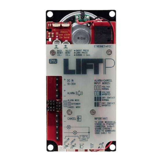
2.5 Description of LEDs, Terminals, Jumpers and Connectors Description of Terminals, Jumpers and Connectors Description of terminals Note You can access the terminals without removing the cover. 2N TELEKOMUNIKACE a.s., www.2n.cz 31/117... - Page 32 Description of terminals and connectors ETHERNET (PoE) RJ-45 LAN connector (PoE 802.3af) DC IN 10–30 V External power DC 10–30 V 0.5 A terminal supply (unless PoE is available) ALARM Voltage 5–48 V DC Use jumpers for configuration. terminal control connection The jumper link is below the...
- Page 33 Indicator connecting DC 12–24 V / 2× 200 mA externally supplied indicators; keep the wiring terminals diagram. “Establishing Yellow The LEDs are not included in the standard delivery connection” LED (excluding the cable version). connector By connecting an external LED you will not deactivate the LED on the board.
- Page 34 Warning Keep polarity for voltage-controlled ALARM and CANCEL buttons (see the instructions on the cover). Caution You are recommended to turn down the speaker volume to minimise the microphone-speaker feedback (echo). LED Functions (Back) State Yellow System at relax Call in progress illuminated Audio test / System menu flashing...
- Page 35 State Blue ALARM activation illuminated CANCEL activation illuminated Note The LEDs are on the LiftIP audio unit back side. LED Functions (Front – during call) Colour Function Yellow Establishing connection Green Connection established Note The LEDs are on the LiftIP audio unit front side. External LEDs can be connected too (Establishing connection, Connection established).
-
Page 36: System Voice Menu
2.6 System Voice Menu System Voice Menu Press the MENU/SELECT button for 3 s to enter the system voice menu. The device starts playing the following message: “System voice menu. Press BACK to quit the menu.” If an error is detected, the error number is played. Then, the current IP address and DHCP are read and the factory reset can be performed. - Page 37 Caution Do not press the SELECT button to enable/disable DHCP or restore the factory settings until you have read the whole message. By restoring the factory settings you delete parameters 1100–1110. Note Error detection 15 seconds to get the link 30 seconds to get the IP address 60 seconds to connect to the SIP Proxy / Lift8 server 2N TELEKOMUNIKACE a.s., www.2n.cz...
-
Page 38: Voice Alarm Station
2.7 Voice Alarm Station Description ® ® Voice Alarm Station is a switch that helps you extend LiftIP with one or more audio units installed on the cabin roof and under the cabin. Operation ® Push Press to call for activation. A call is set up to the number set in 2N LiftIP (ALARM button memory 011 to 016). - Page 39 Caution The audio unit does not contain any call setup LED indicator. A LED is ® shining on the LiftIP audio unit to indicate call setup and connection confirmation. You have to wait for approx. 30 s before setting up a call from another audio unit.
- Page 40 Warning Disconnect LiftIP from the power supply while connecting the IO extender (DC 10–30 V or PoE). Make sure that all the pins are inserted in the 6-pin connector correctly. Keep the correct connector wiring (yellow wire - see the figure below). Wrong wiring may lead to a module damage.
- Page 41 ® Connect the microphone and speaker from LiftIP in the switch. The speaker and microphone connectors are properly marked (SPK and MIC). Pull the cables through the holes. Caution ® If you use the cable version of LiftIP , then insert the cabled microphone in the switch MIC connector.
- Page 42 Break out the cable holes on the switch upper cover. Then replace the switch cover. Use 2 RJ-12 audio unit connectors on the switch side to interconnect the audio unit and the switch using the cable included in the audio unit package. Dimensions Audio unit –...
-
Page 43: Io Extender
2.8 IO Extender Description ® The IO extender helps you extend LiftIP with 1 input and 2 outputs. The purpose of the input is to cancel the rescue mode (if set in parameter 966 – 1 or 3). The input is N/O contact controlled . ®... - Page 44 ® Interconnect LiftIP and the IO extender using a cable (see the figure below). User output Blocking output Switch input Unused Activated at lift blocking N/O contact connection for rescue mode end 2N TELEKOMUNIKACE a.s., www.2n.cz 44/117...
- Page 45 Warning Disconnect LiftIP from the power supply while connecting the IO extender (DC 10–30 V or PoE). Make sure that all the pins are inserted in the 6-pin connector correctly while connecting the IO extender. Keep the correct connector wiring (yellow wire - see the figure below). Wrong wiring may lead to a module damage.
- Page 46 Warning Disconnect LiftIP from the power supply while connecting the IO extender (DC 10–30 V or PoE). Make sure that all the pins are inserted in the connector correctly while connecting the IO extender. Keep the correct connector wiring (yellow wire - see the figure below). Wrong wiring may lead to a module damage.
- Page 47 Outputs Insulation strength 500 V Output type open at relax, galvanically isolated, can switch both voltage polarities 2N TELEKOMUNIKACE a.s., www.2n.cz 47/117...
-
Page 48: Configuration
3. Configuration ® In this section, we describe the LiftIP configuration. Here is what you can find in this section: 3.1 LiftIP Programming 3.2 Programming Function Survey 3.3 IP Camera Configuration 2N TELEKOMUNIKACE a.s., www.2n.cz 48/117... -
Page 49: Liftip Programming
3.1 LiftIP Programming Before You Start Programming Make sure that your phone supports tone dialling (some key phones and PBXs ® may have problems). By default, LiftIP receives DTMF via RFC-2833 or in- band detector (set in-band in parameter 1108 via the Service Tool only). Complete all the values to be modified into a pre-prepared form, which provides a clear table of basic functions. - Page 50 Programming Procedure Having entered the programming mode, you can change any programmable value(s) in any order. Proceed as follows: enter the parameter (service) number and value. Use an asterisk as a separator or Enter. In general, the function has the following format: parameter number value The parameter number has three digits (see the table).
- Page 51 ® If you are not quite sure of how LiftIP will behave after programming, save the filled-in form for later check. Programming via Service Tool This is the easiest programming method. Use the application to get connected to the ® LiftIP IP address.
-
Page 52: Programming Function Survey
3.2 Programming Function Survey The tables below include all the programming functions. Table of Parameters Par. Parameter Range of Default Note name values value ALARM button up to 30 digits: empty Enter and “ “ for a 3-second memory 1 0–9 pause via the Service Tool or using parameter 017. - Page 53 Par. Parameter Range of Default Note name values value 111– Set 1 - Alarm 1–9 1 = with DTMF confirmation (1) call memory 1–6 2 = with pick-up confirmation (for confirmation GSM/UMTS/VoIP only) mode (set 1) 3 = CPC Antenna 4 = CPC Kone 5 = P100 6 = DTMF auto detection (CPC...
- Page 54 Par. Parameter Range of Default Note name values value Set 2 – ALARM up to 30 Entering characters and ' p' 2 button digits: 0–9 for a 1-second pause while memory 1 programming is possible via a PC (use ®...
- Page 55 Par. Parameter Range of Default Note name values value 121 – Set 2 – number 1–6 1 = with confirmation DTMF (1), 2 = confirmation of picking up confirmation (supported only for GSM/UMTS/VoIP), mode 3 = CPC Antenna, 4= CPC KONE, 5 = P100, 6 = autodetection DTMF protocol (CPC Antenna/P100),...
- Page 56 Count of 0–9 If 0 is set, only the first number in the automatic memory is called regardless of the dialling cycles count of stored numbers. for check calls 171– Check call 1–6 1 = with DTMF confirmation (1) memory 1–6 2 = with pick-up confirmation (for confirmation GSM/UMTS/VoIP only)
-
Page 57: Count Of
Par. Parameter Range of Default Note name values value Enter special character into Operational call memory Count of 0–9 automatic dialling cycles for Operational call 181– Operational call 3–6 3 = CPC Antenna memory 1–6 4 = CPC Kone confirmation 5 = P100 mode... - Page 58 Par. Parameter Range of Default Note name values value Manual Click * for confirmation after dialling checking call the service. activation The checking call is set up the moment programming is completed. CU restart Re-enter the valid service password. * Cancel work ...
- Page 59 Par. Parameter Range of Default Note name values value Minimum 0–30 s Set the minimum time in seconds for button pressing which the alarm button needs to be time to trigger pressed to activate the forced/test forced/test alarm. This alarm bypasses the cancel alarm contact status.
- Page 60 Par. Parameter Range of Default Note name values value Cabin up to 10 empty Start announcements in multiple announcement announcements languages in a given order. The sequence in succession sequences can include such numeric (Alarm) data as lift number, etc. List of announcements: Message up to 10...
- Page 61 Par. Parameter Range of Default Note name values value Check call 0–6 0 = disabled mode 1 = enabled, first call in 3 minutes and then as set in parameter 983 2 = enabled, first call in 2 hours and then as set in parameter 983 3 = enabled, call as set in parameter 4 = enabled, call on the nearest day...
- Page 62 Par. Parameter Range of Default Note name values value LED signalling 0–1 Yellow LED permanently on during an according to Alarm Call. EN 81-28 Yellow and green LED flashing alternately after an unsuccessful checking call. Enable xxxxxxx 0000000 The value sets whether or not the operational operational call shall be triggered at calls at events...
- Page 63 Par. Parameter Range of Default Note name values value 1101 IP address empty IP address assigned to the Ethernet interface (VoIP module). ** 1102 Subnet mask empty Gives the subnet bit mask. ** 1103 Default empty Sets the IP address of the router or gateway PC via which communication is made outside the internal network.
- Page 64 Outgoing proxy port. The registrar port port is used, if the outgoing proxy is not set. 1120 RTSP server empty IP camera RTSP address (H.264) (e.g. AXIS rtsp://192.168.1.100/onvif-media /media.amp) 1121 Username empty IP camera login user name 1122 Password ...
- Page 65 Par. Parameter Range of Default Note name values value SNTP server 2 address 1230 Client enabled 0–1 ® Data client enable (refer to the 2N Lift8 manual, Subs. 7.1 Control Panel) 1231 Server IP empty ® Lift8 server IP address ** address 1232 Server port...
- Page 66 Par. Parameter Range of Default Note name values value 1234 Password Make sure that the password matches the intercom password in the Control Panel. ** ® * This parameter can only be set via the voice menu (incoming call to LiftIP ** This parameter can only be set via the Service Tool.
-
Page 67: Ip Camera Configuration
Make sure that the video call receiving phone supports the H.264 codec too. Make sure that the PBX supports the H.264 codec when calling via a SIP Proxy. Video calls have been tested with AXIS cameras (M1054, M3004). 2N TELEKOMUNIKACE a.s., www.2n.cz 67/117... -
Page 68: Function And Use
4. Function and Use ® This section describes the basic and advanced functions of the LiftIP product. Here is what you can find in this section: 4.1 Function Description 4.2 Control Centre Instructions 4.3 Call Confirmation Types 4.4 Audio Unit Audio Test 4.5 ALARM Button Test 4.6 Rescue Process Activation/End 4.7 CPC and P100 Protocols... -
Page 69: Function Description
4.1 Function Description Purpose of Section The purpose of this subsection is to facilitate troubleshooting. If the system does not work correctly and a well-trained technician can monitor its activities as instructed herein, discrepancies can be found easily. The technician can describe the discrepancy and substantially accelerate troubleshooting. - Page 70 Warning If you use CPC or P100, remember to set the check call number that ® routes the call to the Lift8 server . With the fall to sets 011–016, the call may not be confirmed and evaluated properly. Caution A check call can be activated manually via parameter 811.
- Page 71 Incoming Call ® ® The control centre can also call the LiftIP number. LiftIP automatically answers every incoming call, identifies itself and lets you select another function via a voice menu (DISA). You can call an audio unit or enter the programming menu, for example.
- Page 72 Caution If the check call number is not completed (071–076), the call is set up to the numbers in memories 011–016. We recommend you to set the check call receiving number. If CPC/P100 were used and the call were directed ®...
- Page 73 ® delay for LiftIP after ALARM pressing. In this case, if the ALARM button is pressed by mistake, the lift arrives in the next floor and the door opens thus cancelling the call. Or, you can set the minimum button pressing time to prevent unintentional ALARM pressing.
-
Page 74: Control Centre Instructions
4.2 Control Centre Instructions DTMF Control during Call ® Tone dialling can be used for LiftIP control during calls as shown in the table below if Automatic dialling with confirmation is enabled. Commands 1 to 5 are arranged conveniently for typical use. DTMF Function description character... - Page 75 List of 2N ® LiftIP Announcements Announcement Meaning “Please wait for The announcement is played to the lift user when the call is being set connection” up (before confirmation). “This is an emergency The announcement is played to the control centre before call call, to confirm confirmation.
-
Page 76: Call Confirmation Types
4.3 Call Confirmation Types These settings apply to the alarm, check and error reporting calls. 1. With DTMF Confirmation You can store up to 6 phone numbers including redialling attempts for control centre ® ® calls. LiftIP then tries to call the numbers one by one. LiftIP uses DTMF as the most reliable confirmation method. - Page 77 2. Confirmation by Off-Hook This mode is useful where no trained personnel are available as the called person does not have to press any button. The two modes share a set of numbers, count of cycles and responses to dialling situations. The difference is that the no-confirmation mode recognises the ringing tone and if the tone ends before the preset count of rings, it means that the called user is off-hook and this is considered a successful connection.
- Page 78 5. P100 Used wherever the counterparty is equipped with the required SW. When the line is answered, a DTMF character is sent and the lift is identified. The call is either switched to voice communication (alarm call) or confirmed automatically and terminated (check call).
-
Page 79: Audio Unit Audio Test
4.4 Audio Unit Audio Test Use parameter 993 to enable the audio unit test after a check call. If the audio unit is OK, the next check call is made. If an error is detected during the audio test, the next check call is not made. - Page 80 Caution If set via parameter 990 and the Event menu (script), the operational call will be set up twice. 2N TELEKOMUNIKACE a.s., www.2n.cz 80/117...
-
Page 81: Alarm Button Test
4.5 ALARM Button Test This function informs you that the lift cabin button has is stuck. Set the count of seconds for the button to be considered stuck in parameter 969 (ALARM button test). If this happens, the event defined via the Service Tool (Events – Jammed button) will be executed. -
Page 82: Rescue Process Activation/End
4.6 Rescue Process Activation/End Rescue Process Activation Set parameter 992 (rescue password) to activate the rescue process. If an alarm call is set up, the yellow LED keeps shining on the audio unit after the call end to indicate the rescue process activation. -
Page 83: Cpc And P100 Protocols
4.7 CPC and P100 Protocols There are two CPC protocols: KONE and Antenna. The data message consists of: Command - Call type - DATA - ID (974) CPC KONE 2N Ext Call type Command Call type Data ID (974) Alarm 0000000000000 parameter 974 Alarm 2... - Page 84 Caution The Button repaired/Audio repaired information is only transmitted via the 2N Ext protocol. If the 2N Ext mode is not set, the operational call cannot be established. CPC Antenna 2N Ext Call type Command Call type Data ID (974) Alarm 00000 parameter 974...
-
Page 85: P100
Caution The Button repaired/Audio repaired information is only transmitted via the 2N Ext protocol. If the 2N Ext mode is not set, the operational call cannot be established. P100 The data message consists of: Call type - ID (974) - DATA P100 Call type Call type... - Page 86 Example This is only a part of the data message, excluding the beginning, checksum and end 287654321500 - Rescue process ended, identification number (parameter 974) 87654321 Caution The Button repaired/Audio repaired information is only transmitted via the 2N Ext protocol. If the 2N Ext mode is not set, the operational call cannot be established.
-
Page 87: Service Tool
5. Service Tool Here is what you can find in this section: 5.1 Installation and Login 5.2 Introduction to Application 5.3 Use ® Refer to the 2N TELEKOMUNIKACE official websites, LiftIP download section, for the latest application versions. 2N TELEKOMUNIKACE a.s., www.2n.cz 87/117... -
Page 88: Installation And Login
Service Tool installation location: C:\Program Files (x86)\2N TELEKOMUNIKACE 2N LiftIP\ is used by default. Now the application will ask you to enable transmission of system data and software use surveys to help the 2N TELEKOMUNIKACE a.s. company improve the software quality, availability and performance. - Page 89 Application Installation Command Caution Make sure that the command line is started by admin. If it is started by a user, the editor authenticating window will pop up. Note ® LiftIP Service Tool installation requires 500 MB of free disk space at least.
- Page 90 password to be able to establish immediate connection to the device whenever you ® open the application. To use the LiftIP Service Tool for multiple unit administration, click on extended settings. The Connection list will be displayed where you can create and name connections. In this case, do not use the default connection for connecting of new and unknown units.
- Page 91 Scanner Click with the right mouse button to display more options. Click Connect to connect to the selected unit. The configuration option helps you set the network parameters and access password for the selected unit via a proprietary protocol. The next option allows you to add a device to the list as a new connection.
- Page 92 Warning If the Incompatible .NET version message is displayed upon the wizard launch, download the current .NETFX4.0 redistribution from the 2N TELEKOMUNIKACE websites or use the link here The minimum OS requirements are Windows 8/8.1, Windows 7, Windows Vista Note Recommended hardware requirements Microsoft Windows 8/8.1 CZ, Microsoft Windows 7 SP1 CZ, Microsoft Windows Vista SP2 CZ...
-
Page 93: Introduction To Application
5.2 Introduction to Application In this subsection, we will show you the application layout and menus as well as basic controls. The application is divided into three menu levels. The first screen upon start includes Configuration / Parameters / Basic (see the figure below), which displays all of the three menu levels. - Page 94 Note No language change will be executed until the application is restarted. The Status line displays the following information, from the left: Connected to includes the name of the port to which you are currently connected corresponding with your ® PC COM port.
- Page 95 Basic Controls New helps you create a new table of parameters. The existing table will be replaced after a warning. Open from file helps you read the table of parameters from a disk file. Save to file helps you save the current table of parameters into a disk file. Connect device switches the user into the Connect to device menu.
- Page 96 Delete voice message in device helps you delete a message saved in the device memory. Disconnect device helps you log out from a device. ® Upgrade starts FW uploading to 2N LiftIP. 2N TELEKOMUNIKACE a.s., www.2n.cz 96/117...
-
Page 97: Use
5.3 Use Upon the application launch, you get to the Configuration main menu and then to the ® Parameters / Basic menu, where you can find almost all of the LiftIP settings. You are in the offline configuration, which you can modify, prepare for download to an ®... - Page 98 Configuration / Parameters Menu The menu also includes the Expand groups Collapse groups buttons for you to expand the sections and display all the required parameters quickly. Click the Favorites next to the Collapse groups button to display your favourite items in the table. Click on the empty star symbol behind a parameter in the Favorites column to select a new favourite item.
- Page 99 Left – Inactive Filter , Right – Active Filter Each column with the funnel symbol includes its own filter settings; see the figure below. The Contains function finds the searched string in all the column items and returns all the occurrences. Enter a text into the string field and click Filter to activate the filter and display all the searched items in the column.
- Page 100 Use the context menu opened by clicking anywhere in the table or the Alt+R keyboard shortcut to delete the set filters. The pencil symbol is displayed whenever a default parameter is changed to highlight the parameters that have been changed in the configuration. Each table row is equipped with a hint including parameter description...
- Page 101 Events Menu Once the event is detected, an operational call can be made to the number defined in the operational call set, see parameters 081–086. The error information is then transmitted via CPC or P100. Click Upload to device to save the set actions. 2N TELEKOMUNIKACE a.s., www.2n.cz 101/117...
- Page 102 Caution Make sure that the CPC/P100 communication is set properly in parameters 181–186 to make operational calls work. Logs The Logs section helps you view the diagnostic reports included in the log files. No logs are displayed upon the application launch. Download the current logs from a file or the audio unit upon login.
- Page 103 Save the captured log for later analysis in the left-hand bottom part. Click Find to find a message in the log. Enter the string to be searched in the dialogue window. Click Filter to find the first occurrence and Find next to find the next occurrence.
- Page 104 Advanced Settings Save configuration Upload configuration help you save and load your advanced settings onto your PC disk for later use respectively. Logs – Protocol Logs Enable VoIP protocol logs in this submenu to make the device record SIP and RTSP messages and click the respective button to display them as texts.
- Page 105 Protocol Logs The checkbox remains selected until the device is restarted or manually disconnected. This prevents unnecessary memory overload. When the function is activated, the files are deleted automatically. User Messages User Messages helps you replace the default system announcements with user ®...
- Page 106 formatted one. If you just select a message, a message player will become accessible to the right for you to play the message. Standard player functions are available too. Press Play to play the message. To record new messages, select the input source. When the microphone icon shines red, start recording a new message, thus deleting the old one.
- Page 107 Recording Settings Find the Recording settings to the left. Select one of the available input devices in Select source : integrated or external microphone or line input. Mic level defines the microphone input drive level. Mic gain defines the input gain. The total memory ®...
- Page 108 Device / Info Menu Note ® As time is not backed up in LiftIP , any power outage leads to a time setting loss. Time will be restored automatically when the audio unit is connected to a properly set NTP server. Therefore, make sure that time is set correctly.
- Page 109 Device / Upgrade Menu Select Reset to factory defaults to delete all user edited changes and restart the audio unit with the factory default values. Select this option and click Upgrade to reset factory default values upon upgrade. This action will only be performed together with new FW, bootloader or voice menu loading into the audio unit.
-
Page 110: Technical Parameters
6. Technical Parameters Electric Parameters Supply voltage: 10–30 V DC (keep polarity) or 48 V PoE 802.3af Consumption: up to 6 W ALARM and CANCEL voltage range Inputs: 5–48 V DC (keep polarity) Audio Parameters Speaker: integrated 16 Ω / 0.25 W Option to increase the output power to 1 W by connecting a speaker with 4 Ω... -
Page 111: Supplementary Information
7. Supplementary Information ® This section provides supplementary information on the LiftIP product. Here is what you can find in this section: 7.1 Troubleshooting 7.2 List of Terms and Abbreviations 7.3 Directives, Laws and Regulations 7.4 General Instructions and Cautions 2N TELEKOMUNIKACE a.s., www.2n.cz 111/117... -
Page 112: Troubleshooting
7.1 Troubleshooting For the most frequently asked questions refer to faq.2n.cz Have you forgotten your service password? Contact our Technical Support and ® communicate your LiftIP serial number. 2N TELEKOMUNIKACE a.s., www.2n.cz 112/117... -
Page 113: List Of Terms And Abbreviations
7.2 List of Terms and Abbreviations ® Incoming call – call in the control centre – LiftIP direction ® Outgoing call – call in the LiftIP – control centre direction ® Check(ing) call – automatically activated call in the LiftIP –... -
Page 114: Directives, Laws And Regulations
7.3 Directives, Laws and Regulations ® LiftIP conforms to the following directives and regulations: 2014/35/EU on the harmonisation of the laws of the Member States relating to the making available on the market of electrical equipment designed for use within certain voltage limits 2014/30/EU on the harmonisation of the laws of the Member States relating to electromagnetic compatibility... -
Page 115: General Instructions And Cautions
7.4 General Instructions and Cautions Please read this User Manual carefully before using the product. Follow all instructions and recommendations included herein. Any use of the product that is in contradiction with the instructions provided herein may result in malfunction, damage or destruction of the product. The manufacturer shall not be liable and responsible for any damage incurred as a result of a use of the product other than that included herein, namely undue application and disobedience of the recommendations and warnings in contradiction... - Page 116 The consumer shall, without delay, change the access password for the product after installation. The manufacturer shall not be held liable or responsible for any damage incurred by the consumer in connection with the use of the original password. The manufacturer also assumes no responsibility for additional costs incurred by the consumer as a result of making calls using a line with an increased tariff.
- Page 117 2N TELEKOMUNIKACE a.s. Modřanská 621, 143 01 Prague 4, Czech Republic Phone: +420 261 301 500, Fax: +420 261 301 599 E-mail: sales@2n.cz Web: www.2n.cz v2.6.0 2N TELEKOMUNIKACE a.s., www.2n.cz 117/117...
Need help?
Do you have a question about the 2N LiftIP and is the answer not in the manual?
Questions and answers