Table of Contents
Advertisement
Quick Links
For Quick
Start Installation
CopperLink Model CL1300
Long Range Ethernet Extenders
User Manual
Important
This is a Class A device and is intended for use in a light industrial environment. It is
not intended nor approved for use in an industrial or residential environment.
REGULATORY MODEL NUMBER: 03343D1-002
Sales Office:
+1 (301) 975-1000
Technical Support:
+1 (301) 975-1007
E-mail:
support@patton.com
WWW:
www.patton.com
Part Number: 50000047, Rev. A
Revised: November 22, 2019
Advertisement
Table of Contents

Related Manuals for Patton CopperLink CL1300


Summary of Contents for Patton CopperLink CL1300
- Page 1 This is a Class A device and is intended for use in a light industrial environment. It is not intended nor approved for use in an industrial or residential environment. REGULATORY MODEL NUMBER: 03343D1-002 Sales Office: +1 (301) 975-1000 Technical Support: +1 (301) 975-1007 E-mail: support@patton.com WWW: www.patton.com Part Number: 50000047, Rev. A Revised: November 22, 2019...
- Page 2 E-mail: support@patton.com Trademark Statement The term CopperLink is a trademark of Patton Electronics Company. All other trademarks presented in this document are the property of their respective owners. Copyright © 2019, Patton Electronics Company. All rights reserved. The information in this document is subject to change without notice. Patton Electronics assumes no liability for errors that may appear in this document.
-
Page 3: Summary Table Of Contents
CLI Operation and Configuration Contacting Patton for assistance.........................47 . -
Page 4: Table Of Contents
Table of Contents Summary Table of Contents ..........................3 Table of Contents . - Page 5 ........................47 Contacting Patton for Introduction ................................48 Contact information..............................48 Contacting Patton Technical Services for Free Support ...................48 Warranty Service and Returned Merchandise Authorizations (RMAs)..............48 Warranty coverage ............................48 Out-of-warranty service ..........................49...
- Page 6 CopperLink Model CL1300 User Manual Table of Contents Line Coding ................................53 Connectors ................................53 Ethernet Interface..............................53 Line Interface ................................53 Management .................................54 MTBF ...................................54 Power ..................................54 Power Consumption..............................54 Operating Temp..............................54 Humidity ................................54 Altitude .................................54 Enclosure................................54 Dimensions ................................54 Weight ..................................55 Compliance ................................55 ......................56 Factory replacement parts and accessories Factory replacement parts and accessories ......................57...
-
Page 7: List Of Figures
List of Figures CopperLink Model CL1300 and CL1300R ........... 15 CL1300R terminal block power connection . -
Page 8: List Of Tables
List of Tables General conventions ..............12 TCPAM/Rates . -
Page 9: About This Guide
38 describes how use the browser interface that allows you to configure and manage the • Ethernet extender Chapter 5 on page 43 describes how to connect a PC to configure the CopperLink CL1300 using the CLI • Chapter 6 on page 47 contains information on contacting Patton technical support for assistance •... -
Page 10: Precautions
CopperLink Model 1300 User Manual Precautions Notes, cautions, and warnings, which have the following meanings, are used throughout this guide to help you become aware of potential problems. Warnings are intended to prevent safety hazards that could result in per- sonal injury. -
Page 11: Safety When Working With Electricity
CopperLink Model 1300 User Manual Safety when working with electricity • Do not open the device when the power cord is con- nected. For systems without a power switch and without an external power adapter, line voltages are present WARNING within the device when the power cord is connected. -
Page 12: General Observations
CopperLink Model 1300 User Manual In accordance with the requirements of council directive 2002/96/ EC on Waste of Electrical and Electronic Equipment (WEEE), ensure that at end-of-life you separate this product from other waste and scrap and deliver to the WEEE collection system in your country for recycling. - Page 13 CopperLink Model 1300 User Manual Table 1. General conventions Convention Meaning Helvetica type Indicates the names of fields or windows. Garamond bold type Indicates the names of command buttons that execute an action. Angle brackets indicate function and keyboard keys, such as <SHIFT>, <CTRL>, <...
-
Page 14: General Information
Chapter 1 General information Chapter contents CopperLink Model CL1300 overview ........................15 Features .................................16 Power input connector ............................16 External AC universal power supply ........................17 External 48 VDC power supply ........................17... -
Page 15: Copperlink Model Cl1300 Overview
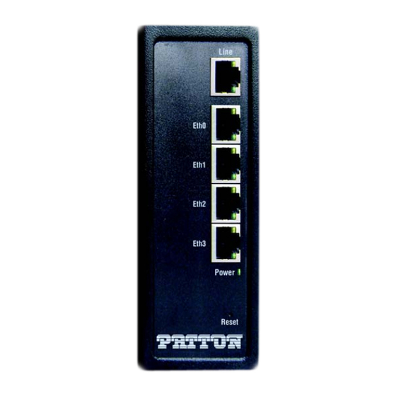
CopperLink Model CL1300 User Manual 1 • General information CopperLink Model CL1300 overview The CL1300 Long Range Ethernet Extender series consists of the CL1300 Ethernet Extender and the CL1300R Indus- (see figure trial Grade Ethernet Extender . Both devices can be placed on a desk or table, but the ruggedized CL1300R can also be mounted on a DIN rail, operates at temperatures of -40 to 85°C, and is available with optional conformal coating to protect against condensing humidity and corrosion. -
Page 16: Features
Automatic learning, aging, and filtering—Keeps local traffic local, ensuring efficient utilization of the long- range link. • Made in the USA—This Patton equipment is designed by Patton engineers and built in our Gaithersburg, Maryland facility. Power input connector Depending on the SKU, the CopperLink device comes with an included AC power supply or it can be con- nected to a DC power supply that is not included. -
Page 17: External Ac Universal Power Supply
CopperLink Model CL1300 User Manual 1 • General information Figure 3. CL1300 power connection External AC universal power supply For additional specifications, see section “Power” on page 54. • Output from power supply: 5 VDC, 2 A • Input to power supply: universal input 100–240 VAC 50/60 Hz 0.3A The external AC adapter shall be a listed limited power source that incorporates a disconnect device and shall be positioned within easy reach of the operator. -
Page 18: Installation
Chapter 2 Installation Chapter contents Introduction ................................19 Configuring DIP Switch S2...........................19 Hardware (DIP switch) configuration ......................21 Installing the device ...............................21 DIN rail installation ............................22 Connecting the Line Interface ..........................23 Connecting the 10/100Base-T Ethernet Interface....................27 Connecting Power ..............................27 CL1300 Series ..............................27 AC power supply ............................27 DC power supply... -
Page 19: Introduction
CopperLink Model CL1300 User Manual 2 • Installation Introduction The Interconnecting cables shall be acceptable for external use and shall be rated for the proper application with respect to volt- age, current, anticipated temperature, flammability, and CAUTION mechanical serviceability. To install the CL1300 Ethernet Extender, do the following: 1. -
Page 20: Removing Dip Switch Cover
CopperLink Model CL1300 User Manual 2 • Installation Figure 4. Removing DIP switch cover figure 5 shows the orientation of the DIP switches in the On and Off positions. Figure 5. DIP switch S2 orientation Configuring DIP Switch S2... -
Page 21: Hardware (Dip Switch) Configuration
CopperLink Model CL1300 User Manual 2 • Installation Hardware (DIP switch) configuration To disable the DIP switches: 1. Power-off the device. 2. Set all DIP switches to off (see figure 5 on page 20). To enable the DIP switches: 1. Power-off the device. 2. -
Page 22: Din Rail Installation
CopperLink Model CL1300 User Manual 2 • Installation DIN rail installation 1. The DIN rail mounting clip on the unit (see figure 6) can be attached to top hat NS 35/7.5 (35 H × 7.5 D mm) and NS 35/15 (35 H × 15 D mm) section types of DIN rail (see figure Figure 6. -
Page 23: Connecting The Line Interface
CopperLink Model CL1300 User Manual 2 • Installation Figure 8. Installing the device onto the DIN rail 3. Rotate the device until the lower DIN rail lip snaps into the lower DIN rail clip slot (see callout 2 on figure The device has been installed on the DIN rail;... -
Page 24: Cl1300R Ports
CopperLink Model CL1300 User Manual 2 • Installation Figure 10. CL1300R ports Observe the signal/pin relationship on the CL1300’s Line interface jack for each pair in figure If you will be installing optional Connect-IT Model 552-E1 surge protectors Note to protect a CL1300R, refer to Appendix E on page 60 for instructions. - Page 25 CopperLink Model CL1300 User Manual 2 • Installation • The RJ-45 Line connector on the CL1300R’s twisted pair interface is polarity insensitive and is wired for a 4-wire interface. • The CL1300MDE port C1 connects to port C2 (CL1300MDE) or the Line port (CL1300/R or CL1300R/R) •...
-
Page 26: Cl1300 Topologies
CopperLink Model CL1300 User Manual 2 • Installation Figure 12. CL1300 Topologies Connecting the Line Interface... -
Page 27: Connecting The 10/100Base-T Ethernet Interface
CopperLink Model CL1300 User Manual 2 • Installation Connecting the 10/100Base-T Ethernet Interface The Ethernet Extender has four unshielded RJ-45 auto-MDIX10/100Base-T interfaces. These are designed to connect directly to a 10/100Base-TX network. Connecting Power Refer to the appropriate section to connect power: •... -
Page 28: Dc Power Supply
CopperLink Model CL1300 User Manual 2 • Installation Figure 13. AC Switching Power Supply The external power adapter shall be a listed limited power source that incorporates a disconnect device and shall be positioned within easy reach of the operator. Ensure that the AC power CAUTION cable meets all applicable standards for the country in which it is to be installed, and that it is connected to a wall outlet which has... -
Page 29: Cl1300R Series
CopperLink Model CL1300 User Manual 2 • Installation • Isolation: 500 VDC • Environment: 0–40°C; 5–95% relative humidity, non-condensing The external DC adapter shall be a listed limited power source that incorporates a disconnect device and shall be positioned within easy reach of the operator. The interconnecting cables CAUTION shall be rated for the proper voltage, current, anticipated tem- perature, flammability, and mechanical serviceability. -
Page 30: Ac Switching Power Supply With Terminal Block Plug
CopperLink Model CL1300 User Manual 2 • Installation 2. If it hasn’t already been done, slide the AC plug that came with the AC switching power supply (see figure 16) onto the AC switching power supply. 3. Connect the AC plug end of the AC switching power supply into an AC power outlet. Figure 16. -
Page 31: Dc Power Supply
CopperLink Model CL1300 User Manual 2 • Installation Figure 17. CL1300R Terminal Block Plug Go to section “Ethernet Extender Status LEDs” on page 32. DC power supply The CL1300R has a built-in internal DC power converter: • Input: Rated voltage: - 12–60 VDC - Rated current: 0.25 A DC Do the following: Connect the 12–60 VDC power source wires to the CL1300R terminal block (see... -
Page 32: Ethernet Extender Status Leds
CopperLink Model CL1300 User Manual 2 • Installation Figure 18. CL1300R Terminal Block Figure 19. Terminal Block Label Go to section “Ethernet Extender Status LEDs” on page 32. Ethernet Extender Status LEDs The LEDs indicate the status of power, Line, and Ethernet connections (see figure 20 on page 33 for CL1300R figure 21... -
Page 33: Cl1300R Power Led
CopperLink Model CL1300 User Manual 2 • Installation Table 3. CL1300 front panel LEDs LED Name LED Function Description Power Indicates power is applied. CopperLink Pair Port is configured as DOWN. One LED for each port (1 on Port is in data mode. CL1314/CL1314R or 2 on SLOW BLINK Port is in handshake mode (looking for... -
Page 34: Configuration
Chapter 3 Configuration Chapter contents Introduction ................................35 Switches.................................36... -
Page 35: Introduction
CopperLink Model CL1300 User Manual 3 • Configuration Introduction Your CopperLink Ethernet Extenders are pre-configured to work in pairs. If the factory installed configuration needs to be adjusted, you can configure the device by using: • DIP switches (while powered off ) (see Section “DIP Switches”... -
Page 36: Dip Switches
CopperLink Model CL1300 User Manual 3 • Configuration no shutdown port line 0 0 service-mode 2-wire mode local bind switch-group DEFAULT LINE_0_0 no shutdown DIP Switches The DIP switches enable you to configure the Local/Remote and TCPAM/Rate preset. These settings are applied when the device powers on, and they cannot be changed while the device is powered on. - Page 37 CopperLink Model CL1300 User Manual 3 • Configuration 4. Set DIP #6–8 to OFF. These are reserved for future use. DIP Switches...
-
Page 38: Wizard Interface
Chapter 4 Wizard Interface Chapter contents Introduction ................................39 Connect with Web GUI............................39... -
Page 39: Introduction
CopperLink Model CL1300 User Manual 4 • Wizard Interface Introduction The CL1300 provides a browser interface that allows you to configure and manage the Ethernet extender. After you set up the IP address for the CL1300, you can access the Web interface applications directly in your Web browser by entering the configured IP address. -
Page 40: Web Wizard Home Page
CopperLink Model CL1300 User Manual 4 • Wizard Interface Figure 23. Web Wizard Home page Once the wizard icon is selected, you will have the options of supported set-ups as shown in figure 24. Click on CL1314 Basic Setup. Figure 24. Choose Wizard Clicking on the CL1314 Basic Setup will bring up the most common configurations used on the CopperLink Ethernet Extenders. - Page 41 CopperLink Model CL1300 User Manual 4 • Wizard Interface User Access: (optional configuration) Users may change the password for the admin user. • Management IP Setup: Static: Create your own IP address, netmask and gateway (optional–the gateway is required for remote management).
-
Page 42: Configure Preview Option
CopperLink Model CL1300 User Manual 4 • Wizard Interface Figure 26. Configure Preview Option When the user chooses the save and reboot option a prompt will ask you to confirm. If the configuration is cor- rect, select Yes as shown in figure Figure 27. -
Page 43: Cli Operation And Configuration
Chapter 5 CLI Operation and Configuration Chapter contents Introduction ................................44 Connect with SSH ..............................44 Change the IP address (default: 192.168.200.10) ....................44 Change the default username..........................44 Save the Configuration ............................44 CopperLink Line Commands..........................44 Local and Remote ............................44 Annex Type ..............................45 Line Rate Configuration ..........................45 Modulation Scheme ............................45... -
Page 44: Introduction
CopperLink Model CL1300 User Manual 5 • CLI Operation and Configuration Introduction You can connect a PC to configure the CopperLink 1300 using the CLI. Connect with SSH 1. Connect the Ethernet cable. 2. Connect the power supply. 3. Connect via SSH to the extender through remote or local IP addresses: –... -
Page 45: Annex Type
CopperLink Model CL1300 User Manual 5 • CLI Operation and Configuration Annex Type Please consult support before changing this setting. node~(pf-dsl)[<name>]# annex-type { b-g | a-f } Line Rate Configuration This will increase the line rate of the CL1300. Your CopperLink 1300 is defaulted to automatically select the optimal rate based on the distance (adaptive). -
Page 46: Exit
CopperLink Model CL1300 User Manual 5 • CLI Operation and Configuration Exit Goes back to parent mode. node~(prt-dsl)[0/0]# exit Show Displays all the configured options of the CL1300 CopperLink port(s) node(cfg)# show prt-line 0 CopperLink Line Commands... -
Page 47: Contacting Patton For
Chapter 6 Contacting Patton for assistance Chapter contents Introduction ................................48 Contact information..............................48 Contacting Patton Technical Services for Free Support ...................48 Warranty Service and Returned Merchandise Authorizations (RMAs)..............48 Warranty coverage ............................48 Out-of-warranty service ..........................49 Returns for credit ............................49 Return for credit policy ..........................49... -
Page 48: Introduction
(RMA). Contact information Patton Electronics offers a wide array of free technical services. If you have questions about any of our other products we recommend you begin your search for answers by using our technical knowledge base. Here, we have gathered together many of the more commonly asked questions and compiled them into a searchable database to help you quickly solve your problems. -
Page 49: Out-Of-Warranty Service
RMA#: xxxx 7622 Rickenbacker Dr. Gaithersburg, MD 20879-4773 USA Patton will ship the equipment back to you in the same manner you ship it to us. Patton will pay the return shipping costs. Warranty Service and Returned Merchandise Authorizations (RMAs) -
Page 50: Compliance Information
Appendix A Compliance information Chapter contents Compliance ................................51 ................................51 Safety ................................51 Radio and TV Interference (FCC Part 15) ......................51 EC Declaration of Conformity ..........................51 Authorized European Representative ........................51... -
Page 51: Compliance
CopperLink Model CL1300 User Manual A • Compliance information Compliance • FCC Part 15, Class A • EN55032, Class A • EN55024 Safety • UL 62368-1/CSA C22.2 N0. 62368-1 • IEC/62368-1 • AS/NZS 62368-1 Radio and TV Interference (FCC Part 15) This equipment generates and uses radio frequency energy, and if not installed and used properly—that is, in strict accordance with the manufacturer's instructions—may cause interference to radio and television recep- tion. -
Page 52: Specifications
Appendix B Specifications Chapter contents Protocol.................................53 Transmission Line ..............................53 Line Rates................................53 Front Panel LED Status Indicators ........................53 Line Coding ................................53 Connectors ................................53 Ethernet Interface..............................53 Line Interface ................................53 Management .................................54 MTBF ...................................54 Power ..................................54 Power Consumption..............................54 Operating Temp..............................54 Humidity ................................54 Altitude .................................54 Enclosure................................54 Dimensions... -
Page 53: Protocol
CopperLink Model CL1300 User Manual B • Specifications Protocol Transparent to higher layer protocols Transmission Line CL1314—Single Twisted Pair (2-wire) CL1324—Two Twisted Pair (4-wire) CL1314—Single Twisted Pair (2-wire) CL1324—Two Twisted Pair (4-wire) Line Rates Rates from 192 kbps to ?15.3 Mbps, selectable in all 64 kbps ?increments starting at 192 kbps Front Panel LED Status Indicators WAN: Link, LAN (Ethernet): Link/Act, Power. -
Page 54: Management
• TFTP firmware upgrade • Import/export config • HTTP • Patton Cloud • restAPI MTBF 4.7 years Power CL1300: External 90–260 VAC, 50–60 Hz (Universal Input) CL1300R: External 90–260 VAC, 50–60 Hz (Universal Input); (Optional) Internal +12 to +48 VDC (10–... -
Page 55: Weight
CopperLink Model CL1300 User Manual B • Specifications Weight CL1300: 2.0 lbs (1.0 kg) CL1300R: 0.7 lbs (0.3 kg) Compliance • FCC Part 15A • CE Mark per EMC directive 89/336/EEC and Low Voltage Directive 73/23/EEC Weight... -
Page 56: Factory Replacement Parts And Accessories
Appendix C Factory replacement parts and accessories Chapter contents Factory replacement parts and accessories ......................57... -
Page 57: Factory Replacement Parts And Accessories
CopperLink Model CL1300 User Manual C • Factory replacement parts and accessories Factory replacement parts and accessories Power Supplies PS-03671H1-004 100-240VAC (12V, DC/2A) Wall mount power adapter with terminal block Power Adapters 12-130 European replacement plug 12-129 North American replacement plug 12-131 United Kingdom plug 12-132... -
Page 58: Interface Pinouts
Appendix D Interface pinouts Chapter contents CopperLink Line port ............................59 2-wire (CL1314R) ............................59 4-wire (CL1324R) ............................59 Ethernet ports 0 to 3 .............................59... -
Page 59: Copperlink Line Port
CopperLink Model CL1300 User Manual D • Interface pinouts CopperLink Line port 2-wire (CL1314R) RJ-45 connector Pin # Signal No connection No connection No connection Ring No connection No connection No connection 4-wire (CL1324R) RJ-45 connector Pin # Signal Line 1 Tip Line 1 Ring No connection Line 0 Tip... -
Page 60: E Installing 552-Gs2 High Speed Surge Protectors
Appendix E Installing 552-GS2 High Speed Surge Protectors Chapter contents Introduction ................................61 Installing the 552-GS2 surge protectors to CL1300R ....................61... -
Page 61: Introduction
E • Installing 552-GS2 High Speed Surge Protectors Introduction The potential threats to CopperLink devices are vast: lightning, AC power induction, electrostatic discharge, ground potential differences, EMI/RFI interference and more. The Patton Model 552 has been designed to greatly reduce these risks. Patton's Connect-IT Model 552 (see figure 28) is easy to install. -
Page 62: Connecting The 552-Gs2 To A Cl1300R
CopperLink Model CL1300 User Manual E • Installing 552-GS2 High Speed Surge Protectors Figure 29. Connecting the 552-GS2 to a CL1300R Do not over-tighten the ground connection. CAUTION Congratulations! The surge protector is installed. If there are additional CL1300R devices to protect, repeat steps 1 through 4 until all 552-GS2 surge protectors have been installed according to the topology that is being used (see figure 12 on page 26).
Need help?
Do you have a question about the CopperLink CL1300 and is the answer not in the manual?
Questions and answers