Table of Contents
Advertisement
Quick Links
CopperLink™ Model CL1211E/CL1212E
Industrial High Speed Ethernet
Extender
User Manual
This is a Class A device and is not intended for use in a residential environment.
Sales Office:
+1 (301) 975-1000
Technical Support:
+1 (301) 975-1007
E-mail:
support@patton.com
WWW:
www.patton.com
Part Number: 07MCL1211E-CL1212E-UM Rev. G
Revised: March 11, 2020
Advertisement
Table of Contents

Related Manuals for Patton CopperLink CL1211E


Summary of Contents for Patton CopperLink CL1211E
- Page 1 User Manual This is a Class A device and is not intended for use in a residential environment. Sales Office: +1 (301) 975-1000 Technical Support: +1 (301) 975-1007 E-mail: support@patton.com WWW: www.patton.com Part Number: 07MCL1211E-CL1212E-UM Rev. G Revised: March 11, 2020...
- Page 2 Under no condition shall Patton Electronics be liable for any damages incurred by the use of this product. These damages include, but are not limited to, the following: lost profits, lost savings and incidental or consequential damages arising from the use of or inability to use this product.
-
Page 3: Summary Table Of Contents
........................34 Contacting Patton for Compliance Information . -
Page 4: Table Of Contents
........................34 Contacting Patton for Introduction ................................35... - Page 5 CopperLink 1211E/1212E User Manual Out-of-Warranty Service ..........................35 RMA Numbers ...............................36 Shipping Instructions ............................36 Compliance Information ...........................37 Regulatory Information ............................38 EMC Directive...
-
Page 6: List Of Figures
List of Figures Typical applications ..............14 CL1200E front panel . -
Page 7: List Of Tables
List of Tables S1 Summary ................30 Local/Remote Unit Configuration . -
Page 8: About This Guide
Appendix D on page 44 provides diagrams of detailed pin assignments • Appendix E on page 47 provides a line range and reach chart for the CL1211E/CL1212E • For best results, read the contents of this guide before you install the CopperLink CL1211E/CL1212E. - Page 9 CopperLink 1211E/1212E User Manual About This Guide Precautions Notes and cautions, which have the following meanings, are used throughout this guide to help you become aware of potential Router modem problems. W ar ni ngs relate to personal injury issues, and Caut i ons refer to potential property damage.
-
Page 10: Safety When Working With Electricity
CopperLink 1211E/1212E User Manual About This Guide Safety When Working With Electricity • This device contains no user serviceable parts. This device can only be repaired by qualified service person- nel. WARNING • Do not open the device when the power cord is con- nected. - Page 11 CopperLink 1211E/1212E User Manual About This Guide This device contains no user serviceable parts. This device can only be repaired by qualified service personnel. WARNING This device is NOT intended nor approved for connection to the PSTN. It is intended only for connection to customer premise equipment.
-
Page 12: General Information
Chapter 1 General information Chapter contents Overview ................................13 Features .................................13 Description................................13 Front panel description............................15... -
Page 13: Overview
1 • General information Overview Thank you for purchasing this Patton Electronics product. This product has been thoroughly inspected and tested and is warranted for one year for parts and labor. If any questions or problems arise during installation or use of this product, contact Patton Electronics Technical Support at +(301) 975-1007. -
Page 14: Typical Applications
CopperLink CL1211E/CL1212E User Manual 1 • General information Figure 1. Typical applications The pair of CL1200E models work together to create a transparent extension between two peered Ethernet LANs using twisted pair (2-wire) or Cat5+. Figure 1 shows typical applications. -
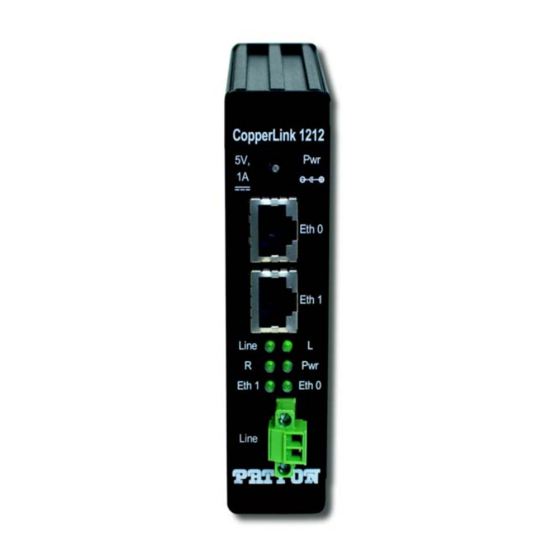
Page 15: Front Panel Description
CopperLink CL1211E/CL1212E User Manual 1 • General information Figure 2. CL1200E front panel Front panel description The following describes the ports and indicators for the CL1200E (see figure • Line—The extension interface used for sending data and power. RJ-45—Interface for two, four, six or eight wires—pin-out to TIA/EIA T568A/B (see section “RJ-45”... -
Page 16: Installation
Chapter 2 Installation Chapter contents Planning the Installation............................17 Installing accessories ..............................17 Installing the DIN Rail Installation Kit; 35MM (INS/A-DIN-35) ..............17 Installing the 19" Rackmount Adjustable Depth 35MM DIN Rail Kit (NS-1001R-19ADJDIN) ....20 Installing the Mounting Ears Installation Kit (INS-KIT-MNTEARS) ............21 Installing the Mounting Plate Installation Kit (INS-KIT-MNTPLATE) ............23 Connecting the Line Interface... -
Page 17: Planning The Installation
CopperLink CL1211E/CL1212E User Manual 2 • Installation Planning the Installation The Interconnecting cables shall be acceptable for external use and shall be rated for the proper application with respect to volt- age, current, anticipated temperature, flammability, and CAUTION mechanical serviceability. -
Page 18: Removing The Rear Panel
CopperLink CL1211E/CL1212E User Manual 2 • Installation Figure 3. Removing the rear panel 2. Install the 35mm DIN clip onto the rear panel using the self-tapping screws (included in the installation kit package) as shown in figure Figure 4. Installing the 35 mm DIN clip 3. -
Page 19: Din Rail Types
CopperLink CL1211E/CL1212E User Manual 2 • Installation Figure 5. Installing the rear panel. 4. The mounting clip can be attached to the following types of DIN rail (see figure – Top hat section types NS 35/7.5 (35 H × 7.5 D mm) and NS 35/15 (35 H × 15 D mm) –... -
Page 20: Installing The 19" Rackmount Adjustable Depth 35Mm Din Rail Kit (Ns-1001R-19Adjdin)
CopperLink CL1211E/CL1212E User Manual 2 • Installation Install the CL1200E to the DIN rail by attaching the appropriate slot on the 35mm clip to the lower DIN rail lip (see callout 1 on figure Figure 7. Installing the CL1200E onto the DIN rail 5. -
Page 21: Installing The Mounting Ears Installation Kit (Ins-Kit-Mntears)
CopperLink CL1211E/CL1212E User Manual 2 • Installation Figure 8. Installing the Rackmount DIN rail onto the rack 2. Refer to section “Installing the DIN Rail Installation Kit; 35MM (INS/A-DIN-35)” on page 17, and per- form steps 1 through 5 to install the CL1200E onto the rail. -
Page 22: Installing The Mounting Ears
CopperLink CL1211E/CL1212E User Manual 2 • Installation Figure 9. Installing the mounting ears 2. Slide a mounting ear into the top slot closest to the CL1200E back panel as shown in figure 3. Slide the remaining mounting ear into the bottom slot closest to the CL1200E right side panel (see figure 4. -
Page 23: Installing The Mounting Plate Installation Kit (Ins-Kit-Mntplate)
CopperLink CL1211E/CL1212E User Manual 2 • Installation 5. Place the CL1200E at the desired location, and install it using hardware appropriate for the type of mount- ing surface. The mounting ears have been installed on the CL1200E; proceed to section “Connecting the Line Interface”... -
Page 24: Connecting The Rj-45 Line Interface
CopperLink CL1211E/CL1212E User Manual 2 • Installation • RJ-45 (see section “Connecting the RJ-45 Line Interface”) • Terminal block (see section “Connecting the Terminal Block Line Interface” on page 24) The CL1200E units work in pairs. The CL1200E/L connects to the Note CL1200E/R. -
Page 25: Connecting The 10/100Base-T Ethernet Interface
CopperLink CL1211E/CL1212E User Manual 2 • Installation Figure 13. CL1200E (terminal block) twisted pair line interface 3. The RJ-45 connector on the CL1200E’s twisted pair interface is polarity insensitive and is wired for a two- wire interface. The signal/pin relationship is shown in (see figure 12). -
Page 26: Connecting Power
CopperLink CL1211E/CL1212E User Manual 2 • Installation Connecting Power The interconnecting cables shall be acceptable for external use and shall be rated for the proper application with respect to volt- age, current, anticipated temperature, flammability, and CAUTION mechanical serviceability. The CL1212E does not have a power switch, so it powers up as soon as it is plugged in. -
Page 27: Configuration
Chapter 3 Configuration Chapter contents Introduction ................................28 Accessing DIP Switch S1 ............................28 Configuring the DIP Switch..........................30 Switch S1-1: Local/Remote Configuration ......................30 Switches S1-2 and S1-3: Symmetric/Asymmetric Operation ................30 Switch S1-5: General Protection (Signal to Noise Ratio) .................31 Installing the Protective Cover..........................31... -
Page 28: Introduction
CopperLink CL1211E/CL1212E User Manual 3 • Configuration Introduction The CL1200E has eight DIP switches (S1) for configuring the unit for a wide variety of applications. This sec- tion describes switch locations and explains the different configurations. Accessing DIP Switch S1 1. -
Page 29: Dip Switch S1 Orientation
CopperLink CL1211E/CL1212E User Manual 3 • Configuration Figure 16. DIP switch S1 orientation Accessing DIP Switch S1... -
Page 30: Configuring The Dip Switch
CopperLink CL1211E/CL1212E User Manual 3 • Configuration Configuring the DIP Switch DIP switch S1 (see figure 16 on page 29) is where you configure the Line interface settings. The settings are described in table Table 1. S1 Summary Position Description... -
Page 31: Switch S1-5: General Protection (Signal To Noise Ratio)
CopperLink CL1211E/CL1212E User Manual 3 • Configuration Switch S1-5: General Protection (Signal to Noise Ratio) Use switch S1-5 to configure line noise protection. Table 4. Signal to Noise Ratio S1-1 Setting CPE/Remote CO/Local • 6dB: Original line noise protection with 6dB SNR •... -
Page 32: Operation
Chapter 4 Operation Chapter contents Introduction ................................33 Front Panel LED Status Monitors .........................33... -
Page 33: Introduction
CopperLink CL1211E/CL1212E User Manual 4 • Operation Introduction Once the CL1200Es are properly installed, they should operate transparently. No user settings are required. This section describes reading the LED status monitors. Before applying power to the CL1200E, please review “Connecting Power”... -
Page 34: Contacting Patton For
Chapter 5 Contacting Patton for assistance Chapter contents Introduction ................................35 Contact information..............................35 Warranty Service and Returned Merchandise Authorizations (RMAs)..............35 Warranty Coverage ............................35 Out-of-Warranty Service ..........................35 RMA Numbers ...............................36 Shipping Instructions ............................36... -
Page 35: Introduction
(RMA). Contact information Patton Electronics offers a wide array of free technical services. If you have questions about any of our other products we recommend you begin your search for answers by using our technical knowledge base. Here, we... -
Page 36: Rma Numbers
RMA#: xxxx 7622 Rickenbacker Dr. Gaithersburg, MD 20879-4773 USA Patton will ship the equipment back to you in the same manner you ship it to us. Patton will pay the return shipping costs. Warranty Service and Returned Merchandise Authorizations (RMAs) -
Page 37: A Compliance Information
Appendix A Compliance Information Chapter contents Regulatory Information ............................38 EMC Directive ...............................38 Low-Voltage Directive (Safety) ........................38 PSTN ................................38 Radio and TV Interference (FCC Part 15) ......................38 CE Declaration of Conformity ..........................38 Authorized European Representative ........................39 Service ...................................39... -
Page 38: Regulatory Information
CopperLink CL1211E/CL1212E User Manual A • Compliance Information Regulatory Information EMC Directive FCC Part 15, Class A • EN55022, Class A • • EN55024 EN50581 • Low-Voltage Directive (Safety) IEC/EN60950-1, 2nd Edition • UL60950-1/CSA C22.2 No. 60950-1 • PSTN This device is not intended nor approved for connection to the PSTN... -
Page 39: Authorized European Representative
Oxford, OX1 1BE, UK Service All warranty and non-warranty repairs must be returned freight prepaid and insured to Patton Electronics. All returns must have a Return Materials Authorization number on the outside of the shipping container. This number may be obtained from Patton Electronics Technical Services at: •... -
Page 40: Specifications
Appendix B Specifications Chapter contents Line Connector ..............................41 LAN Connectors ..............................41 Transmission Line ..............................41 LED Status Indicators ............................41 Power Supply ................................41 Physical .................................41 Operating Temperature Range ........................41 Humidity ................................41 Dimensions ..............................41... -
Page 41: Line Connector
CopperLink CL1211E/CL1212E User Manual B • Specifications Line Connector • RJ-45, Coax or Terminal Block LAN Connectors • CL1212E: 2 RJ-45, 10/100Base-T, IEEE 802.3 Ethernet CL1211E: 1 RJ-45, 10/100 Base-T, 1EEE 802.3 Ethernet • Transmission Line Two-wire unconditioned twisted pair... -
Page 42: C Factory Replacement Parts And Accessories
Appendix C Factory Replacement Parts and Accessories Chapter contents CL1211E/CL1212E Factory Replacement Parts and Accessories................43... -
Page 43: Cl1211E/Cl1212E Factory Replacement Parts And Accessories
CopperLink CL1211E/CL1212E User Manual C • Factory Replacement Parts and Accessories CL1211E/CL1212E Factory Replacement Parts and Accessories Patton Model # Description Base Models 07MCL1212E-UM User Manual Power Supplies PS-03671H1-004 100–240 VAC (5 V, DC/3 A) Wall mount power adapter 12V-PSM... -
Page 44: D Interface Pin Assignment
Appendix D Interface Pin Assignment Chapter contents 10/100Base-T Interface ............................45 RJ-45 ................................45 Line Interface ................................45 RJ-45 ................................45 Terminal Block ...............................46... -
Page 45: 10/100Base-T Interface
CopperLink CL1211E/CL1212E User Manual D • Interface Pin Assignment 10/100Base-T Interface RJ-45 1 TX+/RX+ 2 TX-/RX- 3 RX+/TX+ 4 (no connection) 5 (no connection) 6 RX-/TX- 7 (no connection) 8 (no connection) Figure 18. CL1212E 10/100Base-T RJ-45 Connector Pin-out. Line Interface... -
Page 46: Terminal Block
CopperLink CL1211E/CL1212E User Manual D • Interface Pin Assignment Terminal Block Figure 20. CL1212E Line Interface Terminal Block Pin-out Line Interface... -
Page 47: E Line Rate & Reach Chart
Appendix E Line Rate & Reach Chart Chapter contents Line Rate & Reach Chart Based on 24 AWG (0.5 mm) ..................48... -
Page 48: Line Rate & Reach Chart Based On 24 Awg (0.5 Mm)
CopperLink CL1211E/CL1212E User Manual E • Line Rate & Reach Chart Line Rate & Reach Chart Based on 24 AWG (0.5 mm) Table 6. Line Rate & Reach Chart Using Twisted-Pair (Long Range) Distance in Feet Mbps Mode (Long Range)
Need help?
Do you have a question about the CopperLink CL1211E and is the answer not in the manual?
Questions and answers