Table of Contents
Advertisement
Quick Links
CopperLink™ Model CL1300
Long Range Ethernet Extender
Quick Start Guide
Important—This is a Class A device and is intended for use in a light indus-
trial environment. It is not intended nor approved for use in an industrial or
residential environment.
Part Number: 07MCL1300-QS, Rev. B
Revised: July 31, 2019
Sales Office: +1 (301) 975-1000
Technical Support: +1 (301) 975-1007
E-mail: support@patton.com
Advertisement
Table of Contents

Related Manuals for Patton CopperLink CL1300


Summary of Contents for Patton CopperLink CL1300
- Page 1 Important—This is a Class A device and is intended for use in a light indus- trial environment. It is not intended nor approved for use in an industrial or residential environment. Part Number: 07MCL1300-QS, Rev. B Sales Office: +1 (301) 975-1000 Technical Support: +1 (301) 975-1007 Revised: July 31, 2019 E-mail: support@patton.com...
-
Page 2: Hardware Installation
This device contains no user serviceable parts. The • equipment shall be returned to Patton Electronics for repairs, or repaired by qualified service personnel. WARNING The external power adapter shall be a listed Limited • Power Source. The mains outlet that is utilized to power... - Page 3 Figure 1. CL1300 Ethernet Extender rear panel Figure 2. CL1300R Ethernet Extender front panel Connect the Line Interface To function properly, the CL1300 must be connected using a twisted-pair, uncondi- tioned, dry, metal wire, between 19 (0.9mm) and 26 AWG (0.4mm). Leased circuits that run through signal equalization equipment are not acceptable.
-
Page 4: Connecting Interfaces
(Line 1 TIP) (Line 1 (RING) (no connection) (Line 0 TIP) (Line 0 RING) (no connection) (no connection) (no connection) Figure 3. CL1300 (RJ-45) twisted pair line interface 2.0 Connecting Interfaces 2.1 Connect the Ethernet Interface The Long Range Ethernet Extender has four unshielded RJ-45 auto-MDIX10/100Base-T interfaces. - Page 5 If it hasn’t already been done, slide the AC plug that came with the AC switching power supply (see figure 4) onto the AC switching power supply. Connect the AC plug end of the AC switching power supply into an AC power out- let.
- Page 6 DC power supply. The CL1300 is available with an optional DC power converter (p/n 48V-PSM5) Input: Rated voltage: • - 36–60 VDC - Rated current: 0.25 A DC Output: • - Rated voltage: 5 VDC ± 5%, 5W - Rated current: 1 A DC - 6-inch cable terminated with 2.5 mm barrel plug, center positive Isolation: 500 VDC •...
- Page 7 CL1300R Series The CL1300R comes standard with an AC switching power supply or an internal DC power converter. AC power supply. The CL1300R comes standard with an AC power supply: There is one fuse in the equipment rated at 250V, 500 mA, 2 sec. •...
- Page 8 The external power adapter shall be a listed limited power source that incorporates a disconnect device and shall be positioned within easy reach of the operator. Ensure that the AC power cable meets all applicable standards for the CAUTION country in which it is to be installed, and that it is con- nected to a wall outlet which has earth ground.
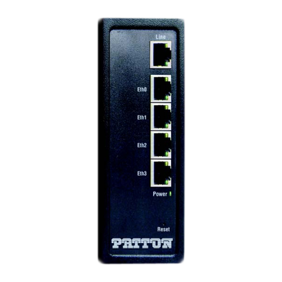
- Page 9 Figure 9. CL1300R Terminal Block Figure 10. Terminal Block Label 2.3 Ethernet Extender Status LEDs The LEDs indicate the status of power, CopperLink, and Ethernet connections (see figure 2 on page 3 for CL1300R or figure 11 on page 10 for CL1300). When extinguished, the LED indicators are clear;...
- Page 10 Table 1. CL1300 front panel LEDs LED Name LED Function Description Power Indicates power is applied. CopperLink Pair Port is configured as DOWN. One LED for each Port is in data mode. port (1 on CL1314/ SLOW BLINK Port is in handshake mode (looking for a CL1314R or 2 on remote signal).
- Page 11 The factory installed configuration is shown below. context ip ROUTER interface LAN ipaddress 192.168.200.11/24 #Remote units are set to 192.168.200.10/24 ipaddress DHCP dhcp context switch-group DEFAULT bind interface ROUTER LAN no shutdown interface ETHERNET_0_0 interface ETHERNET_0_1 interface ETHERNET_0_2 interface ETHERNET_0_3 interface LINE_0_0 port ethernet 0 0 bind switch-group DEFAULT ETHERNET_0_0...
-
Page 12: Wizard Interface
To disable the DIP switches: Power-off the device. 2. Set all DIP switches to OFF. To enable the DIP switches: Power-off the device. 2. Set DIP #1 to LOCAL or REMOTE. When connecting two Copperlink devices, one needs to be configured as Local, and the other Remote: –... - Page 13 Earlier versions predating Internet Explorer 9.0 browser are not compatible with Note the CL1300. 4.1 Connect with Web GUI Connect the Ethernet cable. 2. Connect the power supply. 3. Connect via web browser to the default address 192.168.200.10 or connect to 192.168.200.11 for 2 pack local units.
- Page 14 Figure 13. Web Wizard Home page Once the wizard icon is selected, you will have the options of supported set-ups as shown in figure 14. Click on CL1314 Basic Setup. Figure 14. Choose Wizard Clicking on the CL1314 Basic Setup will bring up the most common configurations used on the CopperLink Ethernet Extenders.
- Page 15 Figure 15. Basic Setup User Access: (optional configuration) Users may change the password for the admin user. Management IP Setup: • - Static: Create your own IP address, netmask and gateway (optional–the gateway is required for remote management). - DHCP: The CL1314 management port will accept an IP address from a DHCP server.
- Page 16 - Service Mode: Configures the number of pairs (wires) you want to use. The CL1300 will default to the maximum number of wires available on your version of the CopperLink. CL1314 (2-wire) or CL1324 (4-wire). - Annex: Consult technical support before changing this setting. - Line Rate Configuration: This will increase the potential line rate of the CL1300.
-
Page 17: Cli Operation And Configuration
Figure 17. Confirmation Typically the time to reboot and reestablish a CopperLink link so it can pass traffic will be less than 2 minutes. 5.0 CLI Operation and Configuration You can connect a PC to configure the CopperLink 1300 using the CLI. 5.1 Connect with SSH Connect the Ethernet cable. - Page 18 5.4 Save the Configuration Follow the command sequence below: node~>enable node~#configure node~(cfg)#copy running-config startup-config 5.5 CopperLink Line Commands Local and Remote This will set the Ethernet Extender as Local or Remote. Local is typically used at the network, Remote is typically used at the remote device or remote network. Your Cop- perLink 1300 when received in a 2pk is already configured one CL1300 as Local and one CL1300 as Remote.
-
Page 19: Additional Information
Displays all the configured options of the CL1300 CopperLink port(s) node(cfg)# show prt-line 0 6.0 Additional Information For detailed information about configuring and operating guidance, set up procedures, and troubleshooting, refer to the CopperLink 1300 Series User Manual available online www.patton.com/manuals CopperLink 1300 Quick Start Guide... -
Page 20: Customer And Technical Support
7.0 Customer and Technical Support Toll-Free VoIP support: call sip:support@patton.com with a VoIP SIP phone Online support: www.patton.com E-mail support: support@patton.com—answered within 1 business day Telephone support: 8:00 am–5:00 pm EST Standard USA +1 (301) 975-1007 Monday–Friday (1300–2200 UTC/GMT) 8:00 am–5:00 pm CET Alternate Switzerland +41 (0)31-985-2555 Monday–Friday... - Page 21 information—a product identifier in the format US: AAAEQ##TXXXX. If requested, this number must be provided to the telephone company. The method used to connect this equipment to the premises wiring and telephone net- work must comply with the applicable FCC Part 68 rules and requirements adopted by the ACTA.
-
Page 22: Authorized European Representative
10.0 Copyright statement Copyright © 2018, Patton Electronics Company. All rights reserved. The information in this document is subject to change without notice. Patton Electron- ics assumes no liability for errors that may appear in this document. CopperLink 1300 Quick Start Guide... -
Page 23: Trademarks Statement
11.0 Trademarks statement The term CopperLink is a trademark of Patton Electronics Company. All other trade- marks presented in this document are the property of their respective owners. 12.0 Warranty, Trademark, & Compliance Information For warranty, trademark and compliance information, refer to the CopperLink User Manual located online at www.patton.com/manuals. - Page 24 ____________________________________________________________________ ____________________________________________________________________ ____________________________________________________________________ ____________________________________________________________________ ____________________________________________________________________ ____________________________________________________________________ ____________________________________________________________________ ____________________________________________________________________ ____________________________________________________________________ ____________________________________________________________________ ____________________________________________________________________ ____________________________________________________________________ ____________________________________________________________________ ____________________________________________________________________ ____________________________________________________________________ CopperLink 1300 Quick Start Guide...
Need help?
Do you have a question about the CopperLink CL1300 and is the answer not in the manual?
Questions and answers