Table of Contents
Advertisement
Quick Links
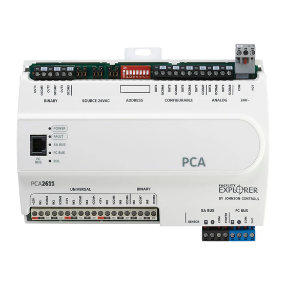
FX-PCA2611-0 Advanced Application Programmable
Controller Installation Instructions
FX-PCA2611-0
Application
The FX-PCA2611-0 Advanced Application Programmable
Controller is part of the Facility Explorer Programmable
Controller (FX-PC) family. The FX-PCA26 Series
controllers run pre-engineered and user-programmed
applications and provide the inputs and outputs required
to monitor and control a wide variety of HVAC equipment.
FX-PCA26 controllers operate on an RS-485 BACnet®
Master-Slave/Token-Passing (MS/TP) Bus as BACnet
Advanced Application Controllers (B-AACs) and integrate
into Johnson Controls® and third-party BACnet systems.
FX-PCA26 controllers include an integral real-time clock,
which enables the controllers to monitor and control
schedules, calendars, and trends, and operate for
extended periods of time as stand-alone controllers when
offline from the system network.
Switchable Communications
Protocols
By default, the FX-PC family controllers and network
sensors communicate using the standard BACnet®
protocol, based on the ANSI/ASHRAE 135-2004.
The BACnet protocol is a standard for ANSI, ASHRAE,
and the International Standards Organization (ISO) for
building controls.
FX-PCG, FX-PCX, and FX-PCV controllers are BTL-
tested and listed as BACnet Application Specific
Controllers (B-ASCs). FX-PCA field controllers are
BTL-listed as BACnet Advanced Application Controllers
(B-AACs). The NS Series Sensors are BTL-listed as
BACnet Smart Sensors (B-SSs).
FX-PCA2611-0 Advanced Application Programmable Controller Installation Instructions
Part No. 24-10143-403, Rev. E
Refer to the
QuickLIT website
Release 10.1 of FX-PCT and later can be used to switch
the Field Bus communications protocol in FX-PC
Controllers to be either the standard BACnet
Master-Slave/Token-Passing (MS/TP) or the N2 protocol.
BACnet MS/TP is the default communications protocol
for all new controllers. Switchable communications
protocols provide a cost-effective upgrade and
modernization path for customers with existing N2
controllers. The Modernization Guide for Legacy N2
Controllers (LIT-12012045) and the controller-specific
documentation provide installation and commissioning
support and include tips for efficient and safe
replacement. Refer to the N2 Compatibility Options
chapter of the Controller Tool Help (LIT-12011147) for
information about mapping N2 Objects in controllers with
switchable communications protocols.
The N2-capable FX-PC controllers can be used as
functional replacements for legacy N2 controllers. The
N2-capable FX-PC controllers:
•
have the I/O quantities and characteristics of the
FX-PC family controllers
•
must be programmed with FX-PCT, which has
programming capabilities that are similar (but not
identical) to HVACPro, GX9100, GPL, and other
legacy tools
•
support SA Bus devices
•
support FX-WRZ wireless sensors from the controller
using the FX-WRZ7860 receiver when configured for
BACnet MS/TP communication
The N2-capable FX-PC controllers:
•
do not support Zone Bus (for example, TMZ sensors
and M100 actuators)
•
do not support pass through in the commissioning
mode
•
do not support remote downloading or commissioning
using BACnet routing
•
do not support wireless connection to the N2 bus
Issued April 2016
for the most up-to-date version of this document.
1
Advertisement
Table of Contents

Related Manuals for Johnson Controls FX-PCA2611-0


Summary of Contents for Johnson Controls FX-PCA2611-0
- Page 1 M100 actuators) • do not support pass through in the commissioning mode • do not support remote downloading or commissioning using BACnet routing • do not support wireless connection to the N2 bus FX-PCA2611-0 Advanced Application Programmable Controller Installation Instructions...
-
Page 2: North American Emissions Compliance
• one 20 cm (8 in.) or longer piece of 35 mm DIN rail and appropriate hardware for DIN rail mount (only) • small straight-blade screwdriver for securing wires in the terminal blocks FX-PCA2611-0 Advanced Application Programmable Controller Installation Instructions... -
Page 3: Din Rail Mount Applications
Figure 2. Mark the mounting hole locations on the wall using the dimensions in Figure 2 and one of the mount positions shown in Figure 1. Or hold the controller up FX-PCA2611-0 Advanced Application Programmable Controller Installation Instructions... - Page 4 LED Status Indicators (See Table FC Bus Port (RJ-12 6-pin Modular Jack) (See FC Bus Port) Binary Outputs (BO) Terminal Block: 24 VAC Triac (See Table Wiring Observe the following guidelines when wiring an FX-PCA2611 controller: FX-PCA2611-0 Advanced Application Programmable Controller Installation Instructions...
- Page 5 4-wire twisted, shielded cable as the FX-PCA2611-0 controller. Observe the following shown in Figure 5. See Comm Bus and Power Supply guidelines when wiring an FX-PCA2611 controller. Terminal Block Rating and Requirements Table for more information. FX-PCA2611-0 Advanced Application Programmable Controller Installation Instructions...
- Page 6 7. The middle terminal on the supply power terminal block is not used. See Comm Bus and Power Supply Terminal Block Rating and Requirements Table for more information about the Supply Terminal Block. FX-PCA2611-0 Advanced Application Programmable Controller Installation Instructions...
-
Page 7: Termination Details
Termination Details A set of termination diagrams provides details for wiring inputs and outputs to the controllers. See the figures in this section for the applicable termination diagrams. FX-PCA2611-0 Advanced Application Programmable Controller Installation Instructions... - Page 8 Table 2: Termination Details Type of Field Type of Termination Diagrams Device Input/Output Temperature Sensor Voltage Input - External Source Voltage Input - Internal Source Voltage Input (Self-Powered) Current Input - External Source (Isolated) FX-PCA2611-0 Advanced Application Programmable Controller Installation Instructions...
- Page 9 Device Input/Output Current Input - Internal Source (2 wire) Current Input - Internal Source (3 wire) Current Input - External Source (in Loop) Feedback from EPP-1000 Dry Contact UI or BI (Binary Input) FX-PCA2611-0 Advanced Application Programmable Controller Installation Instructions...
- Page 10 (Internal Source) FX-PCA3611 does not have Current Output CO or AO Note that FX-PCA3611 does not have 24 VAC Triac Output (Switch Note that Low, External FX-PCA3611 Source) does not have Analog Output (Current) FX-PCA2611-0 Advanced Application Programmable Controller Installation Instructions...
- Page 11 4–20 mA Output to Actuator 4–20 mA Output to Actuator Incremental Control to Actuator (Switch Low, Externally Sourced) (Triac Jumpers Where Applicable) 24 VAC Binary Output (Switch Low, Externally Sourced) (Triac Jumpers Where Applicable) FX-PCA2611-0 Advanced Application Programmable Controller Installation Instructions...
- Page 12 Network Stat with SA Bus Phone Jack (Fixed Address = 199) Note: The bottom jack (J2) on the TE-700 and TE-6x00 Series Sensors is not usable as a zone bus or an connection. FX-PCA2611-0 Advanced Application Programmable Controller Installation Instructions...
-
Page 13: Terminal Wiring Guidelines, Functions, Ratings, And Requirements
Inputs/outputs with cables less than 30 m (100 ft) typically do not require an offset in the software setup. Cable runs over 30 m (100 ft) may require an offset in the input/output software setup. FX-PCA2611-0 Advanced Application Programmable Controller Installation Instructions... - Page 14 Table 3: FX-PCA2611-0 Terminal Blocks, Functions, Ratings, Requirements, and Cables Terminal Block Terminal Function, Ratings, Requirements Determine Wire Size and Label Label Maximum Cable Length UNIVERSAL +15 V 15 VDC Power Source for active (3-wire) input devices Same as (Universal) INn connected to the Universal INn terminals.
- Page 15 Table 3: FX-PCA2611-0 Terminal Blocks, Functions, Ratings, Requirements, and Cables Terminal Block Terminal Function, Ratings, Requirements Determine Wire Size and Label Label Maximum Cable Length ANALOG OUTn Analog Output - Voltage Mode (0–10 VDC) See Guideline C in Table (Outputs)
- Page 16 Table 3: FX-PCA2611-0 Terminal Blocks, Functions, Ratings, Requirements, and Cables Terminal Block Terminal Function, Ratings, Requirements Determine Wire Size and Label Label Maximum Cable Length BINARY OUTn Binary Output - 24 VAC Triac (Internal Power Source) See Guideline C in...
-
Page 17: Cable And Wire Length Guidelines
Use twisted wire cable. The required wire sizes and lengths for high-voltage (>30V) Relay Outputs are determined by the load connected to the relay, and local, national, or regional electrical codes. FX-PCA2611-0 Advanced Application Programmable Controller Installation Instructions... -
Page 18: Maximum Cable Length Versus Load Current
Load Current wiring inputs and outputs. Note: Figure 8 applies to low-voltage (<30V) inputs and outputs only. Figure 8: Maximum Wire Length for Low-Voltage (<30V) Inputs and Outputs by Current and Wire Size FX-PCA2611-0 Advanced Application Programmable Controller Installation Instructions... -
Page 19: Sa/Fc Bus And Supply Power Wiring Guidelines
24 AWG 3-pair CAT3 cable <30.5 Sensor m (100 ft) SA Bus Communications SA Bus Signal Reference and 15 VDC Common 15 VDC Power for devices on the SA bus and Bluetooth Commissioning Converter FX-PCA2611-0 Advanced Application Programmable Controller Installation Instructions... -
Page 20: Setup And Adjustments
To ensure the best bus performance, set sequential to the controller on the bus. device addresses with no gaps in the device address range (4, 5, 6, 7, 8, 9, and so on). The controllers do FX-PCA2611-0 Advanced Application Programmable Controller Installation Instructions... -
Page 21: Setting The N2 Controller Address To Be Greater Than 127
EOL switch on the controller. Failure to disconnect power before changing a jumper or EOL switch position can result in damage to the controller and void any warranties. FX-PCA2611-0 Advanced Application Programmable Controller Installation Instructions... -
Page 22: Setting The Input And Output Jumpers
To set the EOL switch on an FX-PCA2611 controller: Jumpers. Le non-respect de cette précaution risque de 1. Determine the physical location of the controller on provoquer une décharge électrique. the FC bus. FX-PCA2611-0 Advanced Application Programmable Controller Installation Instructions... -
Page 23: Setting Up A Local Display
UI on the FX-PCA2611-0 controller. and the associated power selection jumpers to the right of the BOs terminal block. Table 7: FX-PCA2611-0 UI Inputs and Jumper Labels Universal Input Switch Label on Current Loop DIP Figure 12: Example Binary Outputs and the... -
Page 24: Repair Information
Note: The ZFR-USBHA-0 replaces the IA OEM DAUBI_2400 ZigBee® USB dongle. For additional information on the ZFR-USBHA-0 ZigBee dongle, refer to the FX-ZFR Series Wireless Field Bus System Technical Bulletin (LIT-12011660) or FX-ZFR Series Wireless Field Bus System Quick Reference Guide (LIT-12011696). FX-PCA2611-0 Advanced Application Programmable Controller Installation Instructions... -
Page 25: Technical Specifications
Technical Specifications Table 10: FX-PCA2611-0 Advanced Application Programmable Controller Product Code Numbers FX-PCA2611-0 Advanced Application Programmable Controller Supply Voltage 24 VAC (nominal, 20 VAC minimum/30 VAC maximum), 50/60 Hz, power supply Class 2 (North America), Safety Extra-Low Voltage (SELV) (Europe) - Page 26 The performance specifications are nominal and conform to acceptable industry standard. For application at conditions beyond these specifications, consult the local Johnson Controls® office. Johnson Controls, Inc. shall not be liable for damages resulting from misapplication or misuse of its products.
Need help?
Do you have a question about the FX-PCA2611-0 and is the answer not in the manual?
Questions and answers