Table of Contents
Advertisement
Application
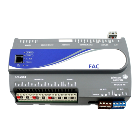
The FAC2611 Advanced Application Field Equipment
Controller (FAC) is part of the Metasys
Equipment Controller family. The FAC26 Series controllers
run pre-engineered and user-programmed applications
and provide the inputs and outputs required to monitor
and control a wide variety of HVAC equipment.
FAC26 field controllers operate on an RS-485 BACnet
TP Bus as BACnet Advanced Application Controllers (B-
AACs) and integrate into Johnson Controls
party BACnet systems.
FAC26 controllers include an integral real-time clock, which
enables the controllers to monitor and control schedules,
calendars, and trends; and operate for extended periods
of time as stand-alone controllers when offline from the
system network.
Switchable communications protocols
By default, the Metasys system FEC Family Controllers
and network sensors communicate using the standard
BACnet protocol based on the ANSI/ASHRAE 135-2008. The
BACnet protocol is a standard for ANSI, ASHRAE, and the
International Standards Organization (ISO) for building
controls.
FEC, VMA16, and VMA18 are BTL-listed as BACnet
Application Specific Controllers (B-ASCs). FAC Field
Controllers and the VMA1930 Field Controller are BTL-
listed as BACnet Advanced Application Controllers (B-
AACs). The NS Series Sensors are BTL-listed as BACnet
Smart Sensors (B-SSs).
Release 10.1 and later of the Controller Configuration Tool
(CCT) can be used to switch the Field Bus communications
protocol in supported FEC Family Field Controllers to be
either the standard BACnet MS/TP or the N2 protocol.
All new controllers use BACnet MS/TP as the default
communications protocol. Switchable communications
protocols in the MS/TP models provide a cost-effective
upgrade and modernization path for customers with
existing N2 controllers.
The N2-capable FEC Family Controllers can be used as
functional replacements for legacy N2 controllers. The N2-
capable FEC Family Controllers:
• have the input and output (I/O) quantities and
characteristics of the FEC Family Controllers
• must be programmed with CCT
• support SA Bus devices
• support WRZ wireless sensors from the controller using
the WRZ-7860 receiver (most models)
• are available in Buy American versions (most models)
FAC2611 Advanced Application Field Equipment
system Field
®
®
and third-
®
Controller Installation Guide
• are listed for UL 864 UUKL/ORD-C100-13 UUKLC 10th
Edition Smoke Control (some models). N2 is now
supported as part of the Metasys 10th Edition listing
for Smoke Control System Equipment. For details, refer
to the Metasys System UL 864 10th Edition UUKL/ORD-
C100-13 UUKLC Smoke Control System Technical Bulletin
(LIT-12012487).
The N2-capable controllers:
MS/
• do not support Zone Bus (for example, TMZ sensors
and M100 actuators) or XT-Bus (System 91) devices (for
example, XT, XTM, and XP modules)
• do not support a wireless connection to the N2 bus
• do not support NxE passthrough
North American emissions compliance
United States
This equipment has been tested and found to comply with
the limits for a Class A digital device pursuant to Part 15
of the FCC Rules. These limits are designed to provide
reasonable protection against harmful interference when
this equipment is operated in a commercial environment.
This equipment generates, uses, and can radiate radio
frequency energy and, if not installed and used in
accordance with the instruction manual, may cause
harmful interference to radio communications. Operation
of this equipment in a residential area may cause harmful
interference, in which case the users will be required to
correct the interference at their own expense.
Canada
This Class (A) digital apparatus meets all the requirements
of the Canadian Interference-Causing Equipment
Regulations.
Cet appareil numérique de la Classe (A) respecte toutes
les exigences du Règlement sur le matériel brouilleur du
Canada.
Installation
Observe these guidelines when installing a field controller:
• Transport the controller in the original container to
minimize vibration and shock damage.
• Verify that all parts shipped with the controller.
• Do not drop the controller or subject it to physical
shock.
Parts included
• One field controller with removable terminal blocks
(Power, SA, and FC bus are removable)
• One installation instructions sheet
Part No. 24-10143-187 Rev. L
2019-10-18
*2410143187L*
(barcode for factory use only)
MS-FAC2611
Advertisement
Table of Contents

Subscribe to Our Youtube Channel
Related Manuals for Johnson Controls FAC2611


Summary of Contents for Johnson Controls FAC2611
- Page 1 • are listed for UL 864 UUKL/ORD-C100-13 UUKLC 10th Edition Smoke Control (some models). N2 is now supported as part of the Metasys 10th Edition listing The FAC2611 Advanced Application Field Equipment for Smoke Control System Equipment. For details, refer Controller (FAC) is part of the Metasys system Field ®...
-
Page 2: Materials And Special Tools Needed
[2 in.] minimum on the top, bottom, and front of the Voltage Analog Input (0-10 VDC), Current Analog Input controller). (4-20 mA), Resistive Analog Inputs (0-600k ohm), or Dry Contact Binary Input. (see Table 2) FAC2611 Advanced Application Field Equipment Controller Installation Guide... -
Page 3: Din Rail Mount Applications
DIN rail. Wall mount applications To mount a field controller directly on a wall or other flat vertical surface: FAC2611 Advanced Application Field Equipment Controller Installation Guide... -
Page 4: Fc Bus Terminal Block
FAC2611 controller. Observe the following guidelines when wiring a controller. Input and Output terminal blocks On most field controller models, all of the fixed input terminal blocks are mounted on the bottom of the FAC2611 Advanced Application Field Equipment Controller Installation Guide... -
Page 5: Fc Bus Port
Figure 7. Do not use the middle terminal on the but continues to be supported. supply power terminal block. See Communications bus and power supply terminal block rating and requirements table for more information about the Supply Power Terminal Block. FAC2611 Advanced Application Field Equipment Controller Installation Guide... -
Page 6: Wireless Network Applications
Note: In wireless network applications, do not connect any wires to the FC bus terminal block. (Connect the SA/FC terminal block on an IOM to an SA bus only.) FAC2611 Advanced Application Field Equipment Controller Installation Guide... - Page 7 Table 2: FAC2611 terminal blocks, functions, ratings, requirements, and cables Terminal Determine wire size and Terminal block label Function, ratings, requirements label maximum cable length Same as (Universal) INn 15 VDC Power Source for active (3-wire) input devices Note: Use 3-wire cable for connected to the Universal INn terminals.
- Page 8 Table 2: FAC2611 terminal blocks, functions, ratings, requirements, and cables Terminal Determine wire size and Terminal block label Function, ratings, requirements label maximum cable length Analog Output - Voltage Mode (0–10 VDC) 10 VDC maximum output voltage 10 mA maximum output current Requires an external load of 1,000 ohm or more.
-
Page 9: Cable And Wire Length Guidelines
Table 2: FAC2611 terminal blocks, functions, ratings, requirements, and cables Terminal Determine wire size and Terminal block label Function, ratings, requirements label maximum cable length Analog Output - Voltage Mode (0–10 VDC) 10 VDC maximum output voltage See Guideline A in Table 3. -
Page 10: Communications Bus And Supply Power Wiring Guidelines
MS/TP Communications Bus Technical Bulletin (LIT-12011034). Termination details See the figures in this section for the applicable termination diagrams. A set of Johnson Controls termination diagrams provides details for wiring inputs and outputs to the controllers. FAC2611 Advanced Application Field Equipment Controller Installation Guide... - Page 11 Table 5: Termination details Type of field Type of Input/ Termination diagrams device Output Temperature Sensor Voltage Input - External Source Voltage Input - Internal Source Voltage Input (Self-Powered) Current Input - External Source (Isolated) FAC2611 Advanced Application Field Equipment Controller Installation Guide...
- Page 12 Output Current Input - Internal Source (2- wire) Current Input - Internal Source (3 wire) Current Input - External Source (in Loop) Feedback from EPP-1000 Dry Contact UI or BI (Binary Input) FAC2611 Advanced Application Field Equipment Controller Installation Guide...
- Page 13 CO or AO (Internal Source) 0–10 VDC Output to Actuator CO or AO (External Source) Current Output CO or AO 24 VAC Triac Output (Switch CO or AO Low, External Source) Analog Output (Current) FAC2611 Advanced Application Field Equipment Controller Installation Guide...
- Page 14 Type of field Type of Input/ Termination diagrams device Output 4–20 mA Output to Actuator 4–20 mA Output to Actuator Incremental Control to Actuator (Switch Low, Externally Sourced) (Triac Jumpers Where Applicable) FAC2611 Advanced Application Field Equipment Controller Installation Guide...
- Page 15 Network Stat with Phone Jack (Fixed SA Bus Address = 199) Note: The bottom jack (J2) on the TE-700 and TE-6x00 Series Sensors is not usable as a zone bus or an SAB connection. FAC2611 Advanced Application Field Equipment Controller Installation Guide...
-
Page 16: Setup And Adjustments
To set the device addresses on Metasys field ® controllers: Set all of the switches on the address DIP switch block (128 through 1) to Off. FAC2611 Advanced Application Field Equipment Controller Installation Guide... -
Page 17: Setting The N2 Controller Address To Be Greater Than 127
Off) 11. Reconnect the 24 VAC supply to the controller. 4 to 127 Used for MS/TP master devices (controllers) that (Switch 128 are hardwired to an SA bus or FC bus. Off) FAC2611 Advanced Application Field Equipment Controller Installation Guide... -
Page 18: Removing The Controller Cover
électrique. to ON, sets the controller as a terminating device on the bus. See Removing the Controller cover for the EOL switch location. The default EOL switch position is Off. FAC2611 Advanced Application Field Equipment Controller Installation Guide... -
Page 19: Binary Output (Bo) Source Power Selection Jumpers
Figure 12: Example binary Outputs and the associated source power jumper positions Setting up a local display FAC2611 models do not have an integral display, but can be connected to a DIS1710 Local Controller Display. For detailed information on setting up and operating... -
Page 20: Troubleshooting Field Controllers
On Steady = Communication lost, waiting to join communication ring Repair information If a field controller fails to operate within its specifications, replace the controller. For a replacement controller, contact your Johnson Controls representative. ® FAC2611 Advanced Application Field Equipment Controller Installation Guide... - Page 21 USB dongle. For additional ® information on the ZFR-USBHA-0 ZigBee dongle, refer to the ZFR1800 Series Wireless Field Bus System Technical Bulletin (LIT-12011295) or ZFR1800 Series Wireless Field Bus System Quick Reference Guide (LIT-12011630). FAC2611 Advanced Application Field Equipment Controller Installation Guide...
-
Page 22: Technical Specifications
Note: Mounting space requires an additional 50 mm (2 in.) space on top, bottom and front face of controller for easy cover removal, ventilation and wire terminations. Weight 0.5 kg (1.1 lb) FAC2611 Advanced Application Field Equipment Controller Installation Guide... -
Page 23: Product Warranty
Canada: UL Listed, File E107041, CCN PAZX7 CAN/CSA C22.2 No.205, Signal Equipment Industry Canada Compliant, ICES-003 Europe: Johnson Controls declares that this product is in compliance with the essential requirements and other relevant provisions of the EMC Directive. Australia and New Zealand: RCM Mark, Australia/NZ Emissions Compliant... - Page 24 FAC2611 Advanced Application Field Equipment Controller Installation Guide...
Need help?
Do you have a question about the FAC2611 and is the answer not in the manual?
Questions and answers