Advertisement
Table of Contents
- 1 Mounting Features and Dimensions
- 2 Wall Mount Applications
- 3 DIN Rail Mount Applications
- 4 Network Topology
- 5 I/O Terminal Blocks, Ratings, and Requirements
- 6 Cable and Wire Length Guidelines
- 7 Maximum Cable Length Versus Load Current
- 8 Communications Bus and Supply Power Wiring Guidelines
- 9 Termination Diagrams
- 10 Setup and Adjustments
- 11 Commissioning Field Controllers
- 12 Troubleshooting Field Controllers
- 13 Repair Information
- 14 Accessories Ordering Information
- 15 Technical Specifications
- 16 Product Warranty
- Download this manual
Application
The FAC4911 Advanced Application Field Equipment
Controller is part of the Metasys
EquipmentController family. The FAC4911
equipment controllers run pre-engineered and user-
programmed applications, and provide the inputs
and outputs required to monitor and control a wide
variety of HVAC equipment.
FAC4911 controllers operate on BACnet
networks and integrate into Johnson Controls
and third-party systems. The controllers include
an integral real-time clock, which enables the
controllers to monitor and control schedules,
calendars, and trends, and operate for extended
periods of time as stand-alone controllers when
offline from the Metasys system network.
The Metasys system FAC family controllers and
network sensors communicate using the BACnet
protocol. The BACnet protocol is a standard for
ANSI, ASHRAE, and the International Standards
Organization (ISO) for building controls. FAC
equipment controllers are BTL-listed and certified as
BACnet Advanced Application Controllers (B-AACs).
North American emissions
compliance
United States
This equipment has been tested and found to
comply with the limits for a Class A digital device
pursuant to Part 15 of the FCC Rules. These limits
are designed to provide reasonable protection
against harmful interference when this equipment
is operated in a commercial environment. This
equipment generates, uses, and can radiate radio
frequency energy and, if not installed and used in
accordance with the instruction manual, may cause
harmful interference to radio communications.
Operation of this equipment in a residential area
may cause harmful interference, in which case the
users will be required to correct the interference at
their own expense.
Canada
This Class (A) digital apparatus meets all the
requirements of the Canadian Interference-Causing
Equipment Regulations.
FAC4911 Advanced Application Field Equipment
system Field
®
/IP
®
®
Controller Installation Guide
Cet appareil numérique de la Classe (A) respecte
toutes les exigences du Règlement sur le matériel
brouilleur du Canada.
Installation
Observe the following guidelines when installing a
field controller:
• To minimize vibration and shock damage,
transport the controller in the original container.
• Verify that all parts shipped with the controller.
• Do not drop the controller or subject it to physical
shock.
Parts included
• One field Controller. (Power and SA bus terminal
blocks are removable)
• One installation instructions sheet.
Materials and special tools needed
• Three fasteners appropriate for the mounting
surface (M4 screws or #8 screws)
• One 23 cm (9.125 in.) or longer piece of 35 mm
DIN rail and appropriate hardware for DIN rail
mount (only)
• Small straight-blade screwdriver for securing
wires in the terminal blocks
*24101431086C*
Part No. 24-10143-1086 Rev. C
2019-10-18
(barcode for factory use only)
MS-FAC4911-0
Advertisement
Table of Contents

Related Manuals for Johnson Controls Metasys FAC4911


Summary of Contents for Johnson Controls Metasys FAC4911
- Page 1 • To minimize vibration and shock damage, FAC4911 controllers operate on BACnet ® transport the controller in the original container. networks and integrate into Johnson Controls ® and third-party systems. The controllers include • Verify that all parts shipped with the controller.
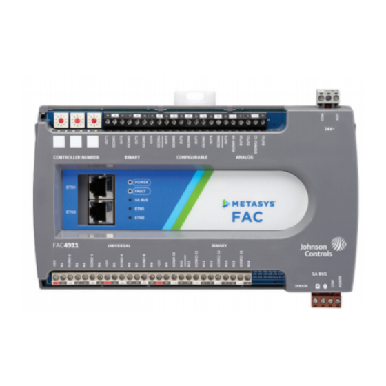
- Page 2 FAC4911 physical features description of the physical features and a reference to further information where required. The following figure displays the physical features of FAC4911, and the accompanying table provides a Figure 1: Physical Features Table 1: Physical features Table 1: Physical features Physical feature: description and references Physical feature: description and references Controller Number Rotary Switches: can be numbered...
- Page 3 Analog Input, Current Mode, 4–20 mA Analog Input, Resistive Mode, 0–2k ohm, resistance temperature detector (RTD) Universal Input (UI) (1k NI [Johnson Controls], 1k PT, A99B SI), negative temperature coefficient (NTC) (10k Type L, 2.252k Type 2) Binary Input, Dry Contact Maintained Mode...
-
Page 4: Mounting Features And Dimensions
Figure 2: Controller Mounting Positions Pull the two bottom mounting clips outward from the controller to the extended position (Figure 3). Hang the controller on the DIN rail by the hooks at the top of the (DIN rail) channel on the back of the controller (Figure 3), and position the controller snugly against the DIN rail. -
Page 5: Network Topology
A ring network is a chain of controllers virtually closed by a software component in an Ethernet switch. Not all switches support the ring topology. The dual-port controller from Johnson Controls ATTENTION supports Media Redundancy Protocol (MRP). MRP allows a chain of Ethernet devices to overcome any single communication failure, with a recovery time Mise En Garde: Risque de dégâts matériels... - Page 6 SA bus terminal block Wire the 24 VAC supply power wires from the transformer to the HOT and COM terminals on the The SA Bus terminal block is a brown, removable, 4- terminal plug as shown in Figure 5. Do not use the terminal plug that fits into a board-mounted jack.
- Page 7 In addition to the wiring guidelines in the following table, observe these guidelines when wiring controller inputs and outputs: • Run all low-voltage wiring and cables separate from high-voltage wiring. • All input and output cables, regardless of wire size or number of wires, should consist of stranded, insulated, and twisted copper wires.
-
Page 8: I/O Terminal Blocks, Ratings, And Requirements
Internal 12 V. 15k Ω pull-up (Inputs) Qualified Sensors: 0–2kΩ potentiometer, RTD (1k Nickel See Guideline A in Table . [ Johnson Controls sensor], 1k Platinum, and A99B Silicon Temperature Sensor) Negative Temperature Coefficient (NTC) Sensor Binary Input - Dry Contact Maintained Mode 1 second minimum pulse width See Guideline A in Table . - Page 9 Table 3: I/O terminal blocks, functions, ratings, requirements, and cables Determine wire size and Terminal block label Terminal label Function, ratings, requirements maximum cable length Analog Output - Voltage Mode (0–10 VDC) 10 VDC maximum output voltage 10 mA maximum output current Requires an external load of 1,000 Ω...
-
Page 10: Cable And Wire Length Guidelines
Cable and wire length guidelines The following table defines cable length guidelines for the various wire sizes that may be used for wiring low-voltage (<30 V) input and outputs. Note: The required wire sizes and lengths for high-voltage (>30 V) Relay Outputs are determined by the load connected to the relay, and local, national, or regional electrical codes. - Page 11 Communications Bus and supply power terminal blocks, ratings, and requirements Table 5: Communications Bus and supply power terminal blocks, functions, ratings, requirements, and cables Terminal Function, electrical ratings/ block/Port Terminal labels Recommended cable type requirements label 0.6 mm (22 AWG) SA Bus Communications stranded, 4-wire (2 twisted- pairs), shielded cable...
-
Page 12: Termination Diagrams
Termination diagrams controllers. See the figures in this section for the applicable termination diagrams. A set of Johnson Controls termination diagrams provides details for wiring inputs and outputs to the Table 6: Termination details Type of field Type of Input/... - Page 13 Table 6: Termination details Type of field Type of Input/ Termination diagrams device Output Current Input - External Source (Isolated) Current Input - Internal Source (2- wire) Current Input - Internal Source (3 wire) Current Input - External Source (in Loop) Feedback from EPP-1000...
- Page 14 Table 6: Termination details Type of field Type of Input/ Termination diagrams device Output Dry Contact UI or BI (Binary Input) 0–10 VDC Output to Actuator CO or AO (External Source) 0–10 VDC Output to Actuator CO or AO (Internal Source) Current Output CO or AO 24 VAC Triac...
- Page 15 Table 6: Termination details Type of field Type of Input/ Termination diagrams device Output Analog Output (Current) 4–20 mA Output to Actuator 4–20 mA Output to Actuator Incremental Control to Actuator (Switch Low, Externally Sourced) 24 VAC Binary Output (Switch Low, Externally Sourced) FAC4911 Advanced Application Field Equipment Controller Installation Guide...
- Page 16 Table 6: Termination details Type of field Type of Input/ Termination diagrams device Output 24 VAC Binary Output (Switch High, Externally Sourced) Incremental Control to Actuator (Switch High, Externally Sourced) Network Stat with Phone Jack (Fixed SA Bus Address = 199) Note: The bottom jack (J2) on the TE-700 and TE-6x00 Series Sensors is not usable as a zone bus or an SAB connection.
-
Page 17: Setup And Adjustments
Table 6: Termination details Type of field Type of Input/ Termination diagrams device Output Network Stat with Terminals (Fixed SA Bus Address = 199) Setup and Adjustments Figure 7: Rotary Switch for Setting Controller Numbers Setting the Controller Number Each controller on a network must have a unique number on the subnet where it resides in order to identify it in the Controller Configuration Tool (CCT) for uploading, downloading, and commissioning. - Page 18 Removing the Controller cover ATTENTION Important: Electrostatic discharge can damage controller components. Use proper Risque de décharge électrique electrostatic discharge precautions during installation, setup, and servicing to avoid Débrancher l'alimentation de l'controller avant tout damaging the controller. réglage du Binary Output Source Power Selection Jumpers.
-
Page 19: Commissioning Field Controllers
Input/Output Wiring Validation Commissioning Field controllers The FAC4911 controllers ship with a default state You commission controllers with the CCT software, that can assist in validating the wiring of the input either via a Bluetooth Wireless Commissioning ® and output terminals prior to download of an Converter, a ZFR wireless dongle, MAP 4.2+/ BACnet application file. -
Page 20: Repair Information
Table 8: Status LEDs and descriptions of LED States LED label LED color Normal LED state Description of LED states Blink - 2 Hz = Data Transmission (normal communication) SA BUS Green Blink - 2 Hz Off Steady = No Data Transmission (N/A - auto baud not supported) On Steady = Communication lost, waiting to join communication ring Repair information If a field controller fails to operate within its... -
Page 21: Accessories Ordering Information
Accessories ordering information Table 9: Accessories Ordering Information Product Code Number Description Refer to the Metasys System Field Equipment Controllers and Related Products Product Bulletin (LIT-12011042) ® IOM Series Controllers for a complete list of available IOM Series Controllers. Refer to the Mobile Access Portal Gateway Catalog Page (LIT-1900869) to identify the appropriate product for your region. -
Page 22: Technical Specifications
Canada: UL Listed, File E107041, CCN PAZX7 CAN/CSA C22.2 No.205, Signal Equipment Industry Canada Compliant, ICES-003 Europe: Johnson Controls, Inc. declares that this product is in compliance with the essential requirements and other relevant provisions of the EMC Directive. Australia and New Zealand: RCM Mark, Australia/NZ Emissions Compliant BACnet Testing Laboratories™... -
Page 23: Product Warranty
This product is covered by a limited warranty, details of which can be found at www.johnsoncontrols.com/buildingswarranty. Single point of contact APAC Europe NA/SA JOHNSON CONTROLS JOHNSON CONTROLS JOHNSON CONTROLS C/O CONTROLS PRODUCT WESTENDHOF 3 507 E MICHIGAN ST MANAGEMENT 45143 ESSEN MILWAUKEE WI 53202 NO. - Page 24 © 2019 Johnson Controls. All rights reserved. All specifications and other information shown were current as of document revision and are subject to change without notice. www.johnsoncontrols.com...
Need help?
Do you have a question about the Metasys FAC4911 and is the answer not in the manual?
Questions and answers