Table of Contents
Advertisement
Quick Links
Application
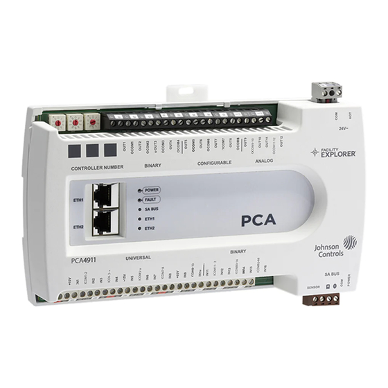
The FX-PCA4911 Advanced Application Controller is part of
the FX-PC Series Programmable Controller family. The FX-
PCA equipment controllers run pre-engineered and user-
programmed applications, and provide the inputs and
outputs required to monitor and control a wide variety of
HVAC equipment.
FX-PCA4911 controllers operate on BACnet
and integrate into Johnson Controls
systems. The controllers include an integral real-time
clock, which enables the controllers to monitor and
control schedules, calendars, and trends, and operate for
extended periods of time as stand-alone controllers when
offline from the Facility Explorer
The FX-PC controllers and network sensors communicate
using the BACnet protocol. The BACnet protocol is
a standard for ANSI, ASHRAE, and the International
Standards Organization (ISO) for building controls. FX-
PCA controllers are BTL-listed and certified as BACnet
Advanced Application Controllers (B-AACs).
North American emissions compliance
United States
This equipment has been tested and found to comply with
the limits for a Class A digital device pursuant to Part 15
of the FCC Rules. These limits are designed to provide
reasonable protection against harmful interference when
this equipment is operated in a commercial environment.
This equipment generates, uses, and can radiate radio
frequency energy and, if not installed and used in
accordance with the instruction manual, may cause
harmful interference to radio communications. Operation
of this equipment in a residential area may cause harmful
interference, in which case the users will be required to
correct the interference at their own expense.
Canada
This Class (A) digital apparatus meets all the requirements
of the Canadian Interference-Causing Equipment
Regulations.
Cet appareil numérique de la Classe (A) respecte toutes
les exigences du Règlement sur le matériel brouilleur du
Canada.
Installation
Observe the following guidelines when installing a
controller:
• To minimize vibration and shock damage, transport the
controller in the original container.
• Verify that all parts shipped with the controller.
• Do not drop the controller or subject it to physical
shock.
FX-PCA4911 Advanced Application Controller
/IP networks
®
and third-party
®
system network.
®
Parts included
• One Advanced Application Controller.
• One installation instructions sheet.
Materials and special tools needed
• Three fasteners appropriate for the mounting surface
(M4 screws or #8 screws)
• One 23 cm (9.125 in.) or longer piece of 35 mm DIN rail
and appropriate hardware for DIN rail mount (only)
• Small straight-blade screwdriver for securing wires in
the terminal blocks
*241014301531C*
Installation Guide
Part No. 24-10143-01531 Rev. C
(barcode for factory use only)
FX-PCA4911-0
2020-11-11
Advertisement
Table of Contents

Subscribe to Our Youtube Channel
Related Manuals for Johnson Controls FX-PCA4911


Summary of Contents for Johnson Controls FX-PCA4911
- Page 1 2020-11-11 Application Parts included • One Advanced Application Controller. The FX-PCA4911 Advanced Application Controller is part of the FX-PC Series Programmable Controller family. The FX- • One installation instructions sheet. PCA equipment controllers run pre-engineered and user- Materials and special tools needed...
- Page 2 FX-PCA4911 physical features The following figure displays the physical features of a FX-PCA4911, and the accompanying table provides a description of the physical features and a reference to further information where required. Figure 1: FX-PCA4911 physical features Table 1: Physical features...
-
Page 3: Mounting Features And Dimensions
FX-PCA4911 model information (including point type counts) Table 2: FX-PCA4911 model information (including point type counts) Communication Protocol BACnet/IP 6-Pin SA Bus with four communicating Modular Jacks sensors Point Types Signals Accepted Number of Points Analog Input, Voltage Mode, 0–10 VDC Analog Input, Current Mode, 4–20 mA... -
Page 4: Din Rail Mount Applications
Drill holes in the wall or surface at the marked Important: Use copper conductors only. Make locations, and insert appropriate wall anchors in all wiring in accordance with local, national, and the holes (if necessary). regional regulations. FX-PCA4911 Advanced Application Controller Installation Guide... -
Page 5: Network Topology
To daisy-chain FX-PCA4911 controllers, connect the controllers to the bus supervisor in a chain with the Ethernet cable connecting to the FX-PCA4911 at the ETH1 Note: The SA PWR terminal supplies 15 VDC. The SA or ETH2 port and connecting to the next device from the PWR terminal can be used to connect (daisy chain) other port. -
Page 6: Terminal Wiring Guidelines, Functions, Ratings, And Requirements
• Inputs or outputs with cables less than 30 m (100 ft) typically do not require an offset in the software setup. Cable runs over 30 m (100 ft) may require an offset in the input/output software setup. FX-PCA4911 Advanced Application Controller Installation Guide... - Page 7 See Guideline A in Cable and Qualified Sensors: 0–2kΩ potentiometer, RTD (1k Nickel wire length guidelines. [Johnson Controls sensor], 1k Platinum, and A99B Silicon Temperature Sensor) Negative Temperature Coefficient (NTC) Sensor Binary Input - Dry Contact Maintained Mode See Guideline A in...
- Page 8 40 mA minimum load current Analog and Binary Output Signal Common All Configurable Outputs (COs) defined as Binary Outputs OCOMn Same as (Configurable) OUTn are isolated from all other commons, including other CO commons. FX-PCA4911 Advanced Application Controller Installation Guide...
-
Page 9: Cable And Wire Length Guidelines
(FX or BCPro): MS/TP Communications Bus for the BCPro™ System Technical Bulletin (LIT-12011908) or FX-PC Series Controllers MS/TP Communications Bus Technical Bulletin (LIT-12011670) for detailed information regarding wire size and cable length requirements for SA and FC buses. FX-PCA4911 Advanced Application Controller Installation Guide... - Page 10 (18 AWG) 2-wire controller) 14 VA Note: The SA Bus wiring recommendations are for MS/TP bus communications at 38.4k baud. For more information, refer to the FX-PC Series Controllers MS/TP Communications Bus Technical Bulletin (LIT-12011670). FX-PCA4911 Advanced Application Controller Installation Guide...
-
Page 11: Termination Diagrams
Termination diagrams See the figures in Table 6 in this section for the applicable termination diagrams. A set of Johnson Controls termination diagrams provides details for wiring inputs and outputs to the controllers. Table 6: Termination details Type of field... - Page 12 Termination diagrams device Output Current Input - External Source (Isolated) Current Input - Internal Source (2- wire) Current Input - Internal Source (3 wire) Current Input - External Source (in Loop) Feedback from EPP-1000 FX-PCA4911 Advanced Application Controller Installation Guide...
- Page 13 0–10 VDC Output to Actuator CO or AO (External Source) 0–10 VDC Output to Actuator CO or AO (Internal Source) Current Output CO or AO 24 VAC Triac Output (Switch CO or AO Low, External Source) FX-PCA4911 Advanced Application Controller Installation Guide...
- Page 14 Type of Input/ Termination diagrams device Output Analog Output (Current) 4–20 mA Output to Actuator 4–20 mA Output to Actuator Incremental Control to Actuator (Switch Low, Externally Sourced) 24 VAC Binary Output (Switch Low, Externally Sourced) FX-PCA4911 Advanced Application Controller Installation Guide...
- Page 15 Table 6: Termination details Type of field Type of Input/ Termination diagrams device Output 24 VAC Binary Output (Switch High, Externally Sourced) Incremental Control to Actuator (Switch High, Externally Sourced) FX-PCA4911 Advanced Application Controller Installation Guide...
-
Page 16: Setup And Adjustments
The controller number is set using three rotary switches (Figure 7) and may be numbered from 000 to 999. The numbers are ordered from left to right, most significant bit (MSB) to least significant bit (LSB). FX-PCA4911 Advanced Application Controller Installation Guide... - Page 17 Analog Input, set the UI's current loop jumper to the the cover from the two upper latches. Enabled position as in Figure 9. Pivot the top of the cover further to release it from the lower two latches. FX-PCA4911 Advanced Application Controller Installation Guide...
-
Page 18: Commissioning The Controllers
(see Table 8). refer to the FX-DIS Local Controller Display Technical Bulletin To make use of this feature, ensure the rotary switches (LIT-12011666). are set to the desired controller number and wire the FX-PCA4911 Advanced Application Controller Installation Guide... -
Page 19: Led Status And Description Table
Off Steady = No Data Transmission (N/A - auto baud not supported) On Steady = Communication lost, waiting to join communication ring Repair information If the controller fails to operate within its specifications, replace the controller. For a replacement controller, contact your Johnson Controls representative. FX-PCA4911 Advanced Application Controller Installation Guide... -
Page 20: Accessories Ordering Information
Refer to the WRG1830/ZFR183x Pro Series Wireless Field Bus System Catalog Page (LIT-1901026) for a list of System available products. WRZ Series Wireless Refer to the WRZ Series Wireless Room Sensors Product Bulletin (LIT-12000653) for specific sensor model Room Sensors descriptions. FX-PCA4911 Advanced Application Controller Installation Guide... -
Page 21: Technical Specifications
United States: UL Listed, File E107041, CCN PAZX, UL 916, Energy Management Equipment Compliance FCC Compliant to CFR47, Part 15, Subpart B, Class A Canada: UL Listed, File E107041, CCN PAZX7 CAN/CSA C22.2 No.205, Signal Equipment Industry Canada Compliant, ICES-003 FX-PCA4911 Advanced Application Controller Installation Guide... -
Page 22: Product Warranty
Contact information Contact your local branch office: www.johnsoncontrols.com/locations Contact Johnson Controls: www.johnsoncontrols.com/ contact-us © 2020 Johnson Controls. All rights reserved. All specifications and other information shown were current as of document revision and are subject to change without notice. www.johnsoncontrols.com...
Need help?
Do you have a question about the FX-PCA4911 and is the answer not in the manual?
Questions and answers