Table of Contents
Advertisement
Application
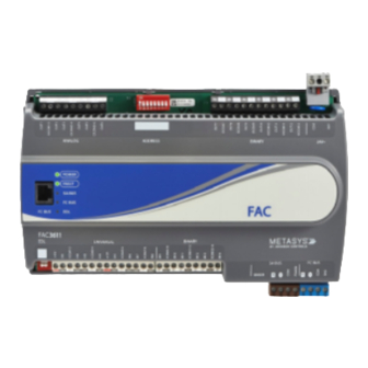
The FAC3613 Advanced Application Field Equipment
Controller (FAC) is part of the Metasys
Field Equipment Controller family. The FAC36
Series controllers run pre-engineered and user-
programmed applications and provides the inputs
and outputs required to monitor and control a wide
variety of HVAC and other facility equipment.
FAC36 controllers operate on an RS-485 BACnet
MS/TP Bus as BACnet Advanced Application
Controllers (B-AACs) and integrate into Johnson
Controls
and third-party BACnet systems.
®
FAC36 field controllers include an integral real-time
clock, which enables the controllers to monitor
and control schedules, calendars, and trends, and
operate for extended periods of time as stand-alone
controllers when offline from the Metasys system
network.
Communications protocols
The FAC3613 field controllers can communicate
using BACnet MS/TP, N2, or wireless Zigbee. By
default, the FAC3613 field controllers communicate
using the standard BACnet MS/TP protocol. The
BACnet protocol is a standard for ANSI, ASHRAE, and
the International Standards Organization (ISO) for
building controls.
The FEC Family Controllers, including the FAC3613,
can be used as functional replacements for
legacy N2 controllers. The N2-capable MS/TP
field controller models provide a cost-effective
upgrade and modernization path for customers
with existing N2 controllers. For installation and
commissioning support, and tips for efficient and
safe replacement, refer to the Modernization Guide
for Legacy N2 Controllers (LIT-12012005) and the
controller-specific documentation. For information
about mapping N2 Objects in controllers with
switchable communications protocols, refer to the
N2 Compatibility Options chapter of the Controller Tool
Help (LIT-12011147).
To configure FAC3613 field controllers to
communicate using the N2 communications
protocol, see
Configuring N2
The FAC3613 field controller can also be installed in
a wireless application using a ZFR/ZFR Pro Wireless
Field Bus Router. To configure these controllers to
FAC3613 Advanced Application Field Equipment
system
®
®
Communications.
Controller Installation Guide
communicate using the wireless communications
protocol, see
Configuring Wireless
Fast persistence
The FAC3613 model has been significantly upgraded
and now includes a fast persistence feature that
allows you to retain data values at a configurable
interval, up to once per second. Persistence refers
to how often samples of data are stored locally. This
upgrade to the persistence feature ensures that
in the event of a problem, such as a loss of power,
more recent data can be retrieved up to the rate that
the data is persisted, minimizing the potential loss of
data. When power is restored, previously persisted
data, up to the rate of persistence, is still available
and accessible. When persistence is configured
for once per second, you risk losing only the most
recent one second of data before the power loss.
Persisting data may be essential for situations that
require greater data accuracy. This may include
certain methods of utility data collection and billing
Attributes that can be persisted in the FAC3613
include: Counter Input Present Value Attributes,
Binary Input, Binary Output, and Binary Value COS
Counts and Active Time Attributes, and PID/PRAC
tuning parameters.
North American emissions
compliance
United States
This equipment has been tested and found to
comply with the limits for a Class A digital device
pursuant to Part 15 of the FCC Rules. These limits
are designed to provide reasonable protection
against harmful interference when this equipment
is operated in a commercial environment. This
equipment generates, uses, and can radiate radio
frequency energy and, if not installed and used in
accordance with the instruction manual, may cause
harmful interference to radio communications.
Operation of this equipment in a residential area
may cause harmful interference, in which case the
users will be required to correct the interference at
their own expense.
Part No. 24-11021-7 Rev. C
2019-10-18
Communications.
*24110217C*
(barcode for factory use only)
MS-FAC3613
Advertisement
Table of Contents

Related Manuals for Johnson Controls FAC3613


Summary of Contents for Johnson Controls FAC3613
- Page 1 Configuring N2 Communications. users will be required to correct the interference at The FAC3613 field controller can also be installed in their own expense. a wireless application using a ZFR/ZFR Pro Wireless Field Bus Router. To configure these controllers to...
-
Page 2: Installation
24 VAC, Class 2/SELV Supply Power Terminal Block (see Device Address DIP Switch Block (see Setting the Device Supply power terminal block) Addresses) Cover Lift Tab (One of Two) Mounting clip FC Bus Terminal Block (see FC bus terminal block FAC3613 Advanced Application Field Equipment Controller Installation Guide... -
Page 3: Mounting Features And Dimensions
• Do not mount the controller on surfaces prone to vibration, such as ductwork. • Do not mount the controller in areas where electromagnetic emissions from other devices or wiring can interfere with controller communication. FAC3613 Advanced Application Field Equipment Controller Installation Guide... -
Page 4: Din Rail Mount Applications
Important: Use copper conductors only. Make holes (or anchors). Carefully tighten all of the all wiring in accordance with local, national, and screws. regional regulations. FAC3613 Advanced Application Field Equipment Controller Installation Guide... -
Page 5: Terminal Blocks And Bus Ports
. FAC3613 physical features for terminal block Figure 5: SA bus terminal block wiring and bus port locations on the FAC3613 controller. Observe the following guidelines when wiring a controller. Input and Output terminal blocks The fixed input terminal blocks are located on the bottom of the controller, and the output terminal blocks are located on the top of the controller. -
Page 6: Supply Power Terminal Block
• Run all low-voltage wiring and cables separate from high-voltage wiring. • All input and output cables, regardless of wire size or number of wires, should consist of stranded, insulated, and twisted copper wires. FAC3613 Advanced Application Field Equipment Controller Installation Guide... - Page 7 (50 Hz at 50% duty cycle) Internal 18 V. 3k ohms pull-up Binary Input Common for all Binary Input (IN) terminals ICOMn Note: All Binary ICOMn terminals share a common, which is isolated from all other commons. FAC3613 Advanced Application Field Equipment Controller Installation Guide...
-
Page 8: Cable And Wire Length Guidelines
(<30 V) input and outputs. Note: The required wire sizes and lengths for high-voltage (>30 V) Relay Outputs are determined by the load connected to the relay, and local, national, or regional electrical codes. FAC3613 Advanced Application Field Equipment Controller Installation Guide... -
Page 9: Maximum Cable Length Versus Load Current
38.4k baud. For more The provides information about the functions, information, refer to the MS/TP Communications ratings, and requirements for the communication Bus Technical Bulletin (LIT-12011034). bus and supply power terminals. The table also FAC3613 Advanced Application Field Equipment Controller Installation Guide... - Page 10 24 VAC Power Supply - Hot Supply 20–30 VAC (Nominal 24 VAC) 0.8 mm to 1.0 mm 24 VAC Power Supply Common (Isolated from (18 AWG) 2-wire all other Common terminals on controller) 14 VA FAC3613 Advanced Application Field Equipment Controller Installation Guide...
-
Page 11: Termination Diagrams
Table 5: Termination details Type of field Type of Input/ Termination diagrams device Output Temperature Sensor Voltage Input - External Source Voltage Input - Internal Source Voltage Input (Self-Powered) FAC3613 Advanced Application Field Equipment Controller Installation Guide... - Page 12 Output Current Input - External Source (Isolated) Current Input - Internal Source (2- wire) Current Input - Internal Source (3 wire) Current Input - External Source (in Loop) Feedback from EPP-1000 FAC3613 Advanced Application Field Equipment Controller Installation Guide...
- Page 13 Actuator CO or AO (External Source) 0–10 VDC Output to Actuator CO or AO (Internal Source) Current Output CO or AO 24 VAC Triac Output (Switch CO or AO Low, External Source) FAC3613 Advanced Application Field Equipment Controller Installation Guide...
- Page 14 Termination diagrams device Output Analog Output (Current) 4–20 mA Output to Actuator 4–20 mA Output to Actuator Incremental Control to Actuator (Switch Low, Externally Sourced) 24 VAC Binary Output (Switch Low, Externally Sourced) FAC3613 Advanced Application Field Equipment Controller Installation Guide...
- Page 15 Address = 199) Note: The bottom jack (J2) on the TE-700 and TE-6x00 Series Sensors is not usable as a zone bus or an SAB connection. Network Stat with Terminals SA Bus Addressable FAC3613 Advanced Application Field Equipment Controller Installation Guide...
-
Page 16: Configuring Wireless Communications
BACnet MS/TP mode, complete the following steps: on, connect the ZFR/ZFR Pro Wireless Field Bus Router to the FC bus port (RJ-12 modular jack) Disconnect the 24 VAC supply from the on the front of the controller. controller. FAC3613 Advanced Application Field Equipment Controller Installation Guide... -
Page 17: Setting The Device Address
OFF for all hard-wired SA and FC bus applications. bus in their numerical device address order. Write each controller's device address on the white label below the DIP switch block on the controller's cover. FAC3613 Advanced Application Field Equipment Controller Installation Guide... -
Page 18: Removing The Controller Cover
The default EOL switch position is OFF. To set the EOL switch on a field controller, complete the following steps: Determine the physical location of the field controller on the FC bus. FAC3613 Advanced Application Field Equipment Controller Installation Guide... -
Page 19: Setting The Input Jumpers
Risk of Electric Shock: Disconnect supply power to the controller before at- tempting to adjust the Binary Output Source Power Table 6: FAC3613 UI Inputs and jumper labels Selection Jumpers. Failure to disconnect the supply power may result in electric shock. -
Page 20: Commissioning Controllers
Beginning at CCT Release 13, the firmware package files are orderable separately; they are not included with CCT. They are obtained from the Metasys FAC3613 Advanced Application Field Equipment Controller Installation Guide... -
Page 21: Led Status And States
Off Steady = EOL switch in Off position devices) Repair information If controller fails to operate within its specifications, replace the controller. For a replacement controller, contact your Johnson Controls representative. FAC3613 Advanced Application Field Equipment Controller Installation Guide... -
Page 22: Accessories Ordering Information
Bus System Product Bulletin (LIT-12011336) for a list of available products. WRZ Series Wireless Refer to the WRZ Series Wireless Room Sensors Product Bulletin (LIT-12000653) for specific sensor model Room Sensors descriptions. FAC3613 Advanced Application Field Equipment Controller Installation Guide... -
Page 23: Technical Specifications
Technical specifications Table 9: FAC3613 Advanced Application Field Equipment Controller Product Code Numbers MS-FAC3613-0 Advanced Application Field Equipment Controller with Fast Persistence 24 VAC (nominal, 20 VAC minimum/30 VAC maximum), 50/60 Hz, power supply Class 2 Power Requirement (North America), Safety Extra-Low Voltage (SELV) (Europe) -
Page 24: Product Warranty
DISTRICT WUXI JIANGSU PROVINCE 214028 CHINA For more contact information, refer to www.johnsoncontrols.com/locations. © 2019 Johnson Controls. All rights reserved. All specifications and other information shown were current as of document revision and are subject to change without notice. www.johnsoncontrols.com...
Need help?
Do you have a question about the FAC3613 and is the answer not in the manual?
Questions and answers