Table of Contents
Advertisement
Quick Links
Advertisement
Table of Contents

Related Manuals for Barco FIMI MDSC8156


Summary of Contents for Barco FIMI MDSC8156
- Page 1 56.2inch LCD Large Screen Monitor MDSC8156...
-
Page 2: General Definitions
0. GENERAL DEFINITIONS Abbreviations European Conformity DEMKO Danish Conformity Mark CCFL Cold Cathode Fluorescent Lamp Canadian Standardisation Authority CVBS Composite Video Blanking and Sync Digital Visual Interface EEDID Enhanced Extended Display Identification Data Electromagnetic Compatibility Electrostatic Discharge Federal Communications Commission Field Replaceable Unit Hot Plug Detect (DVI) International Electrotechnical Commission (Standards) -
Page 3: Table Of Contents
CONTENTS 0. GENERAL DEFINITIONS..............2 1. INTRODUCTION ................5 1.1. EMC Notice ..................6 1.1.1. FCC ....................6 1.1.2. IEC ....................6 1.2. Modification ..................7 1.3. Cables ....................7 2. WARNING..................7 2.1. Power cord ..................7 2.2. Protective earth ................. 8 2.3. - Page 4 7. HANDLING PRECAUTIONS ............. 22 8. PACKAGING ................... 23 9. CONNECTING INSTRUCTION ............24 9.1. Additional Protective Earth Pin ............24 9.2. Connecting AC Power ............... 24 INPUT PANEL DESCRIPTION ............25 10.1. Input label and connections............. 25 10.1.1. Single Link connections ............... 25 10.1.2.
-
Page 5: Introduction
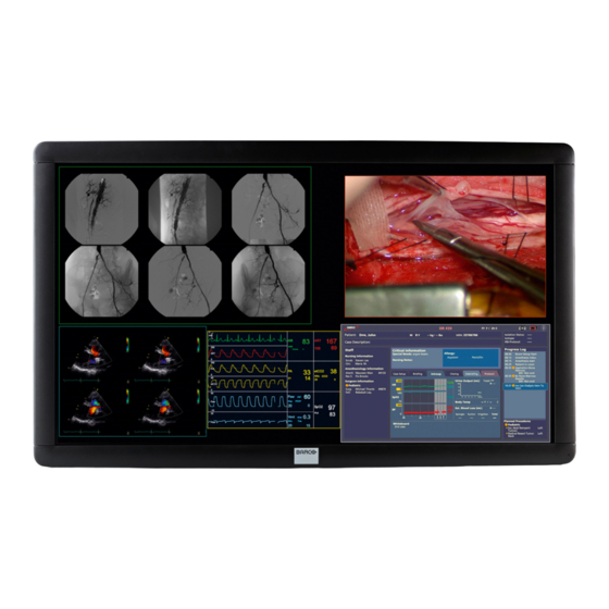
1. INTRODUCTION The BARCO Medical Grade MDSC8156 series are color high resolution liquid crystal displays especially designed for medical imaging applications. The MDSC8156 is a 56” Color Flat Panel Display, intended to replace typical multi-monitor arrays in medical applications, whenever a large screen is needed in addition to high resolution, while offering the same good rendering in greyscale medical imaging thanks to the DICOM conformance. -
Page 6: Emc Notice
Copyright © This manual is copyrighted with all rights reserved. Under the copy rights law, this manual may not be copied, in whole or part, without written consent of BARCO. Under the law, copying includes translating into another language or format. -
Page 7: Modification
1.2. Modification The FCC requires the user to be notified that any changes or modifications made to this device that are not expressly approved by the manufacturer may void the user‟s authority to operate the equipment. 1.3. Cables Connections to the I/O ports must be made with shielded signal cables and metallic RFI / EMI connectors to maintain compliance with Electromagnetic Compatibility Regulations.. -
Page 8: Protective Earth
2.2. Protective earth To avoid the risk of electric shock, this equipment must only be connected to a supply mains with protective earth. (Class I Equipment) 2.3. Installation The equipment should be installed near an easily accessible outlet. Do not install or leave the monitor: ... -
Page 9: Transportation
2.6. Transportation Disconnect all cables from the monitor when transporting. When you transport this LCD display, hold the base sections of the display stand firmly in both hands. If you drop the monitor, you may be injured or the monitor may be damaged. When you transport this monitor for repair or shipment, use the original cardboard box and packing materials. -
Page 10: Cleaning Instruction
2.10. Cleaning Instruction Front panel (for display versions with protective glass) ● To clean the glass, it is recommended: Cleaning materials: e.g. soft cotton cloth window leather Aqueous solution, neutral and weakly e.g. Flux alkaline window cleaner without Ajax additives of abrasive substances: Permitted portion of ammonia <... - Page 11 Front panel ( for display versions without protective glass ) ● Clean the acrylic front panel using a soft cotton cloth, lightly moistened with a watery solution or a mild commercial glass-cleaning product. ● Wipe with a soft cotton cloth. Cabinet ●...
-
Page 12: Disposal Of The Lcd Monitor
3. DISPOSAL OF THE LCD MONITOR During the design of MDSC8156 LCD monitor, special attention has been placed to the environmental impact of the product: packaging, product‟s weight and energy consumption have been optimized. Then, please consider the following notes in the disposal of the product. The monitor‟s packaging is re-usable, please retain the packaging for future use. -
Page 13: Directive 2002/96/Ec On Waste Of Electrical And Electronic Equipment (Weee)
According to what declared by our components supplier, this product is RoHS compliant. 3.3. Directive 1907/2006/EC on Registration, Evaluation, Authorization and Registration of Chemicals (REACH) Information on REACH Substances of Very High Concern (SVHCs) in our products can be found on the BARCO website www.BARCO.com/about/sustainability/reach. The information will be regularly updated. -
Page 14: Power Management
3.4. Power management If the power management function of your computer is enabled, your monitors turns ON and OFF automatically. You can control power management features from your computer. MODE NOTE POWER (typical) Power ON - Green blinking black screen <50 W for 5 sec (**) Power ON... - Page 15 Color Chromaticity x=0.285 y=0.293 (White) Typ. Viewing angle +/- 88° Typ. (H&V) Display Size 1244.16 (H) x 699.84 (V) 56.2” Diagonal size Active area (mm) 1244.16 (H) x 699.84 (V) Bezel Opening Area 1252.1 (H) x 707.8 (V) Inputs 4 synchronous SL DVI 1920*1080@60Hz-Single Link mode 2 synchronous DL DVI 1920*2160@60Hz-Dual Link mode Outputs 5V x 4, 3.5 mm plug near DVI plug...
-
Page 16: Dimensions
5. DIMENSIONS MDSC8156 family 1350 Front View Bottom View... - Page 17 Side View...
- Page 18 General View for display without protective glass...
- Page 19 General View for display with protective glass...
-
Page 20: Mounting Instruction
6. MOUNTING INSTRUCTION Before unpacking the monitor, prepare a suitable workspace. You need a stable and level surface near a grounded wall outlet in an area that is relatively free of glare from sunlight or other sources of bright light.. For best performance, do not block the cooling vents. - Page 21 The monitor is provided with VESA 400 mounting interface evaluated with a safety factor 6; a suitable mechanical suspension has to be provided in the final installation. M6 screw(s) (not provided) (not provided) (not provided)
-
Page 22: Handling Precautions
7. HANDLING PRECAUTIONS The support system of the 56” monitor must be designed in accordance with the requirements of IEC 60601-1 standard (appropriate tensile factor). -
Page 23: Packaging
8. PACKAGING In the case a monitor has to be replaced in the field the packaging has been studied to be reused, the top and bottom covers of the packaging are equal; so you can remove the top and use it as the bottom for the return shipping and use the bottom as top to make the case complete again. -
Page 24: Connecting Instruction
9. CONNECTING INSTRUCTION 9.1. Additional Protective Earth Pin External ground safety connector (To fix by screw with lock washer M4x12 max). Protective Earth Pin 9.2. Connecting AC Power Plug the receptacle end of the cord set into the AC power adapter, then plug the power connector of the adapter into the power port of the monitor. -
Page 25: Input Panel Description
INPUT PANEL DESCRIPTION 10.1. Input label and connections 5V connection is available with the specific purpose to power an external DVI extender. No other uses of the +5V are allowed. The +5V is available on the 4 plugs marked with warning labels and on the pin 16 of each DVI connector. All the +5V connections are in parallel;... - Page 26 The Input / Output signals connectors shall be connected to medical device only in compliance with UL 60601-1; CAN / CSA – C22.2 N° 601.1 – M90; EN / IEC 60601-1. If connected to different type of equipments further evaluation in accord the above mentioned standards shall be done.
- Page 27 DVI 4 input (Microcross™ DVI-D female connector) Pin 1 : D2_RX - (T.M.D.S.) Pin 13 : D3_RX + (T.M.D.S.) Pin 2 : D2_RX + (T.M.D.S.) Pin 14 : +5V (from the video source system) Pin 3 : GND (Data 2 shield) Pin 15 : GND Pin 4 : D4_RX - (T.M.D.S.) Pin 16 : + 5V Power for DVI extenders...
-
Page 28: Control Panel Description
10.2. Control Panel Description On the bottom side part of the unit, the following controls are placed: Power On/Off Enter Esc / Back (Menu‟) (Menu‟) Move Cursor Up Move Cursor Down / Increase Value / Decrease Value (Menu‟) (Menu‟) Brightness Up Brightness Down 10.2.1. -
Page 29: Front Led
10.2.2. Front Led GREEN = Correct video timing and calibration GREEN (blinking) = Boot phase at switching on (approx 5 or 15 seconds if splash screen is enabled) ORANGE = Out of calibration ORANGE (blinking) = Incorrect video timing (at least one of four input) = Stand By RED (blinking) = DIAGNOSTIC ERROR (PWS, Panel Temperatures) -
Page 30: On Screen Display (Osd)
ON SCREEN DISPLAY (OSD) 11.1. Menu structure A description of the OSD structure is shown below: MAIN MENU MONITOR INFO HW REL FW REL OUT MODE DVI PWR IN DVI PWR OUT REMAIN LIFE OUT MODE NATIVE DICOM (FACTORY) DICOM (USER) COLOR (FACTORY) COLOR (USER) USER SETTING... - Page 31 OSD SETTING HOR POSITION LEFT to RIGHT VER POSITION TOP to BOTTOM DISABLE / 10”/ 20”/ 30”/ 45”/ 60”/ 90” OSD TIME-OUT DISABLE / 10”/ 1’ LCD TIME-OUT PRODUCT INFO MODEL PRODUCT NUM SERIAL NUM HW REL FW REL FSL REL FDL REL SERVICE SPLASH SCREEN...
-
Page 32: Osd Controls (On Screen Display)
11.2. OSD Controls (ON Screen Display) Trough the OSD menu, any user available function can be easily and intuitively accessed. 11.2.1. Working in the OSD Menu 1) Press the Enter key to display the OSD MENU (or the request to input the password, if enabled) 2) Press the Up + or Down –... -
Page 33: Out Mode
Pressing the Esc key, you will go back to the Main Menu, with cursor ready to the next item. MONITOR INFO -> OUT MODE USER SETTING OSD SETTING PRODUCT INFO SERVICE By selecting the OUT MODE item and pressing the touching Enter key, the relative window appears. Here following the meaning of each item of this menu: Out Mode 11.2.4. -
Page 34: User Setting
Pressing the Esc key, you will go back to the Main Menu, with cursor ready to the next item. MONITOR INFO OUT MODE -> USER SETTING OSD SETTING PRODUCT INFO SERVICE By selecting the USER SETTING item and pressing the touching Enter key, the relative window appears. Here following the meaning of each item of this menu: User Setting 11.2.5. -
Page 35: Osd Setting
selecting one of these parameters, the relative mode will be loaded in ‘real time’ on the NOTE: monitor (DICOM OFFSET loads DICOM (USER) mode, COLOR TEMP loads COLOR (USER) mode, and GAMMA COMP loads COLOR (USER) mode), so you can see image modifications selecting the parameter and adjusting the values. -
Page 36: Product Info
Pressing the Esc key, you will go back to the Main Menu, with cursor ready to the next item. MONITOR INFO OUT MODE USER SETTING OSD SETTING -> PRODUCT INFO SERVICE By selecting the PRODUCT INFO item and pressing the touching Enter key, the relative window appears. Here following the meaning of each item of this menu: Product Info 11.2.7. -
Page 37: Service
Pressing the Esc key, you will go back to the Main Menu, with cursor ready to the next item. MONITOR INFO OUT MODE USER SETTING OSD SETTING PRODUCT INFO -> SERVICE By selecting the SERVICE item and pressing the touching Enter key, the relative window appears (if it is not password protected) Here following the meaning of each item of this menu: 11.2.8. - Page 38 Key lock example at SERVICE menu level: MONITOR INFO OUT MODE USER SETTING OSD SETTING PRODUCT INFO -> SERVICE Enter Key _ _ _ _ Password request Enter/Down/Up/esc Keys ** _ _ Insert password Password KO Password OK WRONG PASSWORD ! SERVICE - >...
-
Page 39: Factory Preset Video Timings
FACTORY PRESET VIDEO TIMINGS 12.1. Video Format Timing Single Link Mode - 3840x2160 (4 x DVI Single Link inputs, each at 1920x1080@60Hz) For each (1,2,3,4) Single Link inputs: Hor. Pixels = 1920 Pixels Ver. Pixels = 1080 Pixels Hor. Frequency = 67.680 Ver. -
Page 40: Communication Link
COMMUNICATION LINK 13.1. Serial RS232 Interface A serial RS232 interface allows for the remote control of the monitor. The most important operating parameters can be set by the serial interface RS232 DSUB-9 connector: Pinout: not used not used Tx-Data not used Rx-Data not used not used... -
Page 41: Identification Label
IDENTIFICATION LABEL 14.1. Rating Label Position Manufacturing Date Model number Type number Code number (12NC) Factory address Serial number BARCO K code AN=Origin code (FIMI) 00 = Technical level yy= Year (11=2011) ww= Week (01 to 52) nnnnnn= progressive number... -
Page 42: Rating Label Content
14.2. Rating Label Content MDSC8156 GR full version (with protection glass & redundant power supply) MDSC8156 R light version (w/o protection glass, with redundant power supply) MDSC8156 basic version (w/o protection glass & redundant power supply) -
Page 43: Symbols
SYMBOLS The following symbols may appear on the product or its accessory: WARNING: this symbol alerts the user that important information concerning operation and maintenance are provided. The information should be read carefully WARNING: dangerous voltage Disconnect supply before service Compliance with 2002/96/EC (WEEE Directive) Consult instructions for use Compliance with Demko IEC/EN 60601 (Medical Standard) - Page 44 FIMI S.r.l. Saronno - Italy All rights are reserved. Reproduction in whole or in part is prohibited without the written consent of the copyright owner Printed in Italy (Rev. 1.3) 4519 206 1076. 1 a451920610761a...
Need help?
Do you have a question about the FIMI MDSC8156 and is the answer not in the manual?
Questions and answers