
Related Manuals for Barco MDSC-2232 Series


Summary of Contents for Barco MDSC-2232 Series
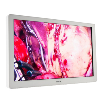
- Page 1 MDSC-2232 32” Full HD surgical display User Guide MDSC-2232 DDI MDSC-2232 MNA ENABLING BRIGHT OUTCOMES...
- Page 2 Barco NV Beneluxpark 21, 8500 Kortrijk, Belgium www.barco.com/en/support www.barco.com Registered office: Barco NV President Kennedypark 35, 8500 Kortrijk, Belgium www.barco.com/en/support www.barco.com...
-
Page 3: Table Of Contents
Table of contents 1 Welcome!.......................................... 7 About the product....................................8 What’s in the box....................................8 About this user guide ..................................9 2 Parts, controls and connectors..............................11 Front view......................................12 Rear view......................................12 Connector view ....................................13 2.3.1 MDSC-2232 DDI version ............................13 2.3.2 MDSC-2232 MNA version............................13 Protective earth pin..................................14 Connector pin assignments ..............................15 2.5.1... - Page 4 OSD menu activation..................................31 OSD menu navigation ..................................31 Shortkey functions..................................32 4.6.1 Main source selection...............................33 4.6.2 Multi-image configuration ............................33 4.6.3 Zoom factor selection ...............................33 4.6.4 Brightness adjustment..............................34 Extended keyboard functions..............................34 4.7.1 Main source selection...............................35 4.7.2 Second source selection............................35 4.7.3 Multi-image configuration ............................35 4.7.4 Common Functions: Transfer function selection..................36 4.7.5...
- Page 5 5.5.2 Power on DVI 2 ................................51 5.5.3 DVI Output ..................................51 5.5.4 Keyboard lock ................................52 5.5.5 Keyboard backlight ..............................52 5.5.6 Power Saving ................................53 6 Important information..................................55 Safety information...................................56 Environmental information.................................59 Biological hazard and returns ..............................61 Regulatory compliance information ............................61 EMC notice ......................................62 Cleaning and disinfection ................................65 Explanation of symbols................................66 Legal disclaimer....................................69...
- Page 6 K5902105 (451920611795) /04 MDSC-2232...
-
Page 7: Welcome
Welcome! K5902105 (451920611795) /04 MDSC-2232... -
Page 8: About The Product
Welcome! 1.1 About the product Overview Barco's MDSC-2232 is a 32-inch full HD surgical display. Purpose-built for the operating room, the MDSC- 2232 offers an easy-clean design, smart mechanics and the most detailed images in the operating room today. Ease of mind Perfect hand-eye coordination: The display’s high brightness, high contrast and full HD resolution provide... -
Page 9: About This User Guide
Welcome! 1.3 About this user guide Overview This manual provides support to the user during the installation, set up and utilization of the MDSC-2232 display. Depending on the specific version that has been purchased, some of the features and options described in this document may not apply to the display in user’s hands. - Page 10 Welcome! K5902105 (451920611795) /04 MDSC-2232...
-
Page 11: Parts, Controls And Connectors
Parts, controls and connectors K5902105 (451920611795) /04 MDSC-2232... -
Page 12: Front View
Parts, controls and connectors 2.1 Front view Overview Image 2-1 Input Selection key Multi-image selection key / Down key Image zoom key / Up key OSD Menu key / Enter key Brightness decrease / Left key Brightness increase / Right key Stand-by key / Power mode LED Keyboard lock/unlock button (membrane switch at the bottom of the display) A 7-key capacitive keypad is located on the front of the display. -
Page 13: Connector View
Parts, controls and connectors Cable routing channel Cable routing channel expansion clip Connector compartment cover 2.3 Connector view 2.3.1 MDSC-2232 DDI version Overview 18 19 Image 2-3 DVI-2 in Potential Equalization pin (POAG) SDI-2 out SDI-2 in SDI-1 out SDI-1 in Sync CVBS in CVBS out... -
Page 14: Protective Earth Pin
R/Pr B/Pb S-Video in Service (*) Nexxis OR functionality: for more detailed information on Barco's Nexxis integrated OR solution please refer to the dedicated user guides. Please visit my.barco.com to obtain these user guides. (**) SDI is not always present in combination with Nexxis input. -
Page 15: Connector Pin Assignments
Parts, controls and connectors 2.5 Connector pin assignments 2.5.1 Input power connector Overview Image 2-6 Not connected +24 VDC Shield +24 VDC The ground and the shield connections on the power input connector have no Protective Earth function. A Protective Earth connection is provided via a dedicated pin (see “Protective earth pin”, page 14). -
Page 16: Dvi-2 Connector (Dvi-D)
Parts, controls and connectors C2: Analog Green C3: Analog Blue C4: Analog horizontal sync C5: Analog GND return (analog R, G, B) (*) +5 VDC output selectable on either pin 14 or 16 via the OSD menu. (+5V ± 10% @ 500mA (max)) PC analog (VGA) input source can be connected to the DVI-I input connector using a DVI-I to VGA adapter. -
Page 17: Rs232 Connector
Parts, controls and connectors Not connected SCL (for DDC) SDA (for DDC) Not connected D1_Rx- (T.M.D.S.) D1_Rx+ (T.M.D.S.) GND (data 1 shield) Not connected Not connected +5V output (*) GND (cable sense) Hot plug detect D0_Rx- (T.M.D.S.) D0_Rx+ (T.M.D.S.) GND (data 0 shield) Not connected Not connected GND (clock shield) -
Page 18: Mini Usb Connector
Parts, controls and connectors 2.5.7 Mini USB connector Overview Image 2-12 +5 VDC Data - Data + Not connected 2.5.8 DisplayPort connector Overview (sink side pin-out) 19 17 15 13 11 9 20 18 16 14 12 10 8 Image 2-13 ML_Lane 3 (n) ML_Lane 3 (p) ML_Lane 2 (n) - Page 19 Parts, controls and connectors Luminance (Y) Chroma (C) SG: Shielded Ground K5902105 (451920611795) /04 MDSC-2232...
- Page 20 Parts, controls and connectors K5902105 (451920611795) /04 MDSC-2232...
-
Page 21: Display Installation
Display installation K5902105 (451920611795) /04 MDSC-2232... -
Page 22: Cover Removal
Display installation 3.1 Cover removal To remove the connector compartment cover Slide the connector compartment cover downwards to get access to the connectors. Image 3-1 3.2 Interface connection About the interfaces The MDSC-2232 can have multiple different video inputs connected (depending on the display version). Switching between the different inputs can be easily done by pressing the direct access key for this. -
Page 23: Mdsc-2232 Mna Version
Display installation Image 3-2 Connect one or more of the available video sink(s) to the corresponding video outputs. • SDI: and/or • CVBS: • S-Video: • DVI: (to be configured in OSD menu, see “DVI Output”, page 51) Image 3-3 WARNING: To maintain compliance with EMC regulation, use only shielded interface cables for the connection to peripheral devices. - Page 24 Display installation • SDI: SDI is not always present in combination with Nexxis input. • R/G/B/S: • R/G/B (SOG): • Y/Pb/Pr: • CVBS: • S-Video: Image 3-4 Connect one or more of the available video sink(s) to the corresponding video outputs. •...
-
Page 25: Nexxis Or
Display installation 3.3 Nexxis OR Overview Connecting your MDSC-2232 to Barco's Nexxis OR system allows you to distribute video, graphics, audio and computer data over the IP network, in raw uncompressed format, inside the operating room and even between surgical suites. -
Page 26: Cable Routing
Display installation Image 3-8 3.5 Cable routing To route the cables For displays to be mounted on a VESA arm with internal cable routing provisions, route all cables through the cable routing channel, then reinstall the connector compartment without removing the expansion clip. Image 3-9 For displays to be mounted on a VESA arm or stand without internal cable routing provisions, first remove the expansion clip from the connector compartment cover, then route all cables through it while reinstalling the... -
Page 27: Vesa Mount Installation
Display installation 3.6 VESA mount installation To install the display on a VESA mounting solution The display can be attached to a VESA 100 mm or VESA 200 mm arm or stand. Image 3-11 The VESA mounting holes at the back of the display are provided with M4-type blind fasteners to fix the VESA mounting plate. - Page 28 Display installation K5902105 (451920611795) /04 MDSC-2232...
-
Page 29: Daily Operation
Daily operation K5902105 (451920611795) /04 MDSC-2232... -
Page 30: On/Off Switching
Daily operation 4.1 On/Off switching The procedures below consider that DC power is supplied to the display. Please check the status of the power mode LED to verify that your display is supplied with DC power (see “Power status LED ”, page 31). -
Page 31: Power Status Led
Daily operation 4.3 Power status LED About the power status LED The behavior of the power LED shows the status of the unit: • Off: Hard power OFF (power supply is unplugged) • Blinking orange: Soft power OFF (switched off by using the stand-by key ( )) •... -
Page 32: Shortkey Functions
Daily operation Picture Profile Factory Brightness Contrast Saturation Color temperature 6500K Gamma Native Sharpness DVI 1280x800@60Hz Image 4-2 Menu Sub-menu Status bar Legend (shows the functionality associated to each keyboard key) Selector/Slider Item To navigate through the OSD menu Image 4-3 •... -
Page 33: Main Source Selection
Daily operation Unlike the extended keyboard functions (described in next chapter), the shortkey functionality is immediately available without the need to first enable this in the OSD menu. When the extended keyboard functionality is enabled, all the shortkey functions described below (except for the brightness adjustment), will no longer be available and will be replaced by the corresponding extended keyboard functions described in the next chapter. -
Page 34: Brightness Adjustment
Daily operation 4.6.4 Brightness adjustment To quickly adjust the brightness While no OSD Menu is on the screen, press the Brightness decrease ( ) or Brightness increase ( ) keys to adjust the brightness as desired. Brightness Image 4-5 When the extended keyboard functionality is enabled, this shortkey functions will remain available. 4.7 Extended keyboard functions About extended keyboard functions The concept of the extended keyboard is to present a large selection of functions immediately available to the... -
Page 35: Main Source Selection
Daily operation Zoom factor selection 4.7.1 Main source selection To quickly select the main source While no OSD Menu is on the screen, press the Input selection key ( ) to bring up the main source quick selection menu. Toggle the available main source options by pressing the key corresponding to the desired option. If two options are available for one key, the first key press will select the upper option, a second press selects the lower option. -
Page 36: Common Functions: Transfer Function Selection
Daily operation Multi image config. Native Aspect Fill Small Large None Image 4-9 4.7.4 Common Functions: Transfer function selection To quickly select the transfer function While no OSD Menu is on the screen, press the Image zoom key ( ) to bring up the common functions quick selection menu. -
Page 37: Common Functions: Zoom Factor Selection
Daily operation 4.7.6 Common Functions: Zoom factor selection To quickly select the zoom factor While no OSD Menu is on the screen, press the Image zoom key ( ) to bring up the common functions quick selection menu. Toggle the available zoom factors by repeatedly pressing the key until the desired zoom factor is shown. - Page 38 Daily operation K5902105 (451920611795) /04 MDSC-2232...
-
Page 39: Advanced Operation
Advanced operation K5902105 (451920611795) /04 MDSC-2232... -
Page 40: Osd Picture Menu
Advanced operation 5.1 OSD picture menu 5.1.1 Profile About profiles To select a profile means to load a set of predefined video parameters like Brightness, Contrast, Saturation, Input selection (Primary & Secondary), Multi-image layout selection, etc. The user can modify the default video parameters associated to each profile and save the new parameters setting under the User 1, User 2 or User 3 profile. -
Page 41: Saturation
Advanced operation 5.1.4 Saturation To adjust the saturation level Bring up the OSD main menu. Navigate to the Picture menu. Enter the Saturation submenu. The command bar Saturation is highlighted. Set the saturation level as desired and confirm. 5.1.5 Color temperature About color temperature presets The available color temperature presets for your display are: •... -
Page 42: Picture Advanced Menu
Advanced operation To select a gamma preset Bring up the OSD main menu. Navigate to the Picture menu. Enter the Gamma submenu. Select one of the available gamma presets and confirm. 5.1.7 Sharpness To adjust the sharpness level Bring up the OSD main menu. Navigate to the Picture menu. -
Page 43: Image Position
Advanced operation Enter the Smart Video submenu. Select one of the available Smart Video presets and confirm. 5.2.3 Image Position This menu item is only available when VGA input is connected. To adjust the image position Bring up the OSD main menu. Navigate to the Picture advanced menu. -
Page 44: Display Format Menu
Advanced operation 5.2.6 Clock/Line This menu item is only available when VGA input is connected. About clock/line If the result of the Auto Adjustment procedure described above isn’t satisfactory, the Clock/Line can be manually adjusted by following this procedure. To manually adjust the phase Bring up the OSD main menu. -
Page 45: Component Mode
Advanced operation 5.3.2 Component Mode About component modes The available component modes for your display are: • YPbPr • To select the component mode Bring up the OSD main menu. Navigate to the Display Format menu. Enter the Component Mode submenu. Select one of the available component modes and confirm. -
Page 46: 2Nd Picture Mode
Advanced operation 5.3.5 2nd Picture Mode About 2 picture modes The available 2 picture modes for your display are: • • Small PiP: 30% of Primary height in top-right corner • Large PiP: 50% of Primary height in top-right corner •... -
Page 47: 2Nd Picture Position
Advanced operation 5.3.7 2nd Picture Position About 2 picture positions The available 2 picture positions for your display are: • Top Right • Top Left • Bottom Right • Bottom Left To select the 2 picture position Bring up the OSD main menu. Navigate to the Display Format menu. -
Page 48: Failover Mode
Advanced operation • Français • Deutsch • Español • Italiano To select the language Bring up the OSD main menu. Navigate to the Configuration menu. Enter the Language submenu. Select one of the available languages and confirm. 5.4.3 Failover mode About failover mode This function allows the automatic switch to a defined Backup source when the Main input signal is missing. -
Page 49: Osd Setting
Advanced operation • Zoom factor selection To enable/disable the extended keyboard Bring up the OSD main menu. Navigate to the Configuration menu. Enter the Extended keyboard submenu. Enable/Disable the extended keyboard as desired and confirm. 5.4.5 OSD setting 5.4.5.1 OSD Horizontal Position To adjust the OSD horizontal position Bring up the OSD main menu. -
Page 50: Save Profile
Advanced operation The available profiles to recall from your display are: • Factory • X Ray • User 1 • User 2 • User 3 To recall a profile Bring up the OSD main menu. Navigate to the Configuration menu. Enter the Recall Profile submenu. -
Page 51: Power On Dvi 2
Advanced operation 5.5.2 Power on DVI 2 About power on DVI 2 This setting allows you to select the pin of DVI port 2 connector on which the +5V DC supply is applied. The available options are: • Disabled • +5V on Pin 14 •... -
Page 52: Keyboard Lock
Advanced operation DVI Output option Main picture 2nd picture “DVI 1” “DVI 2” “None” SDI 2 Other MDSC-2232 MNA version DVI Output option Main picture 2nd picture “DVI” “Nexxis” “None” Nexxis Other Nexxis Nexxis Other Other Nexxis Other To select the DVI output Bring up the OSD main menu. -
Page 53: Power Saving
Advanced operation 5.5.6 Power Saving About power saving When the active input(s) is (are) missing, this setting allows the display to switch off the backlight and enter a low power mode. In this status the availability of the selected input is checked periodically. The unit can exit from power save mode in two cases: 1. - Page 54 Advanced operation K5902105 (451920611795) /04 MDSC-2232...
-
Page 55: Important Information
Important information K5902105 (451920611795) /04 MDSC-2232... -
Page 56: Safety Information
Important information 6.1 Safety information General recommendations Read the safety and operating instructions before operating the device. Retain safety and operating instructions for future reference. Adhere to all warnings on the device and in the operating instructions manual. Follow all instructions for operation and use. Electrical Shock or Fire Hazard To prevent electric shock or fire hazard, do not remove cover. - Page 57 Important information Mission critical applications We strongly recommend there is a replacement monitor immediately available in mission critical applications. Use of Electrical Surgical Knives Provide as much distance as possible between the electrosurgical generator and other electronic equipment (such as monitors). An activated electrosurgical generator may cause interference with them. The interference can activate the OSD menu of the display and as such disrupt the functionality of the display.
- Page 58 Sufficient expertise is required for installing this equipment, especially to determine the strength of the wall for withstanding the display's weight. Be sure to entrust the attachment of this equipment to the wall to licensed contractors of Barco and pay adequate attention to safety during the installation and usage. •...
-
Page 59: Environmental Information
Electronic Products ” (Also called RoHS of Chinese Mainland), the table below lists the names and contents of toxic and/or hazardous substances that Barco’s product may contain. The RoHS of Chinese Mainland is included in the MCV standard of the Ministry of Information Industry of China, in the section “Limit Requirements of toxic substances in Electronic Information Products”. - Page 60 Mainland, marked with the Environmental Friendly Use Period (EFUP) logo. The number inside the EFUP logo that Barco uses (please refer to the photo) is based on the “General guidelines of environment-friendly use period of electronic information products” of Chinese Mainland.
-
Page 61: Biological Hazard And Returns
Important information 绿色自我声明符合性标志可参见电子档文件 The green SDoC mark is visible in the digital version of this document. RoHS Directive 2011/65/EC on the restriction of certain hazardous substances in electrical and electronic equipment. According to what declared by our components suppliers, this product is RoHS compliant. 6.3 Biological hazard and returns Overview The structure and the specifications of this device as well as the materials used for manufacturing makes it... -
Page 62: Emc Notice
The manufacturing country of the product is indicated on the product label (“Made in …”). Importers contact information To find your local importer, contact one of Barco’s regional offices via the contact information provided on our website (www.barco.com). FCC Class B (valid for MDSC-2232 DDI version) This device complies with Part 15 of the FCC Rules. - Page 63 Important information Electromagnetic environment – Compliance Emissions test Guidance RF emissions Group 1 The MDSC-2232 uses RF energy only for its internal function. CISPR 11 Therefore, its RF emissions are very low and are not likely to cause any interference in nearby electronic equipment.
- Page 64 Important information IEC 60601-1-2 4 edition Electromagnetic (2014) Immunity test Compliance level environment – guidance Test levels Voltage dips, short < 5% U (> 95% dip in < 5% U (> 95% dip in U Mains power quality interruptions and voltage ) for 0.5 cycle for 0.5 cycle should by that of a typical...
-
Page 65: Cleaning And Disinfection
Important information IEC 60601-1-2 4 edition Electromagnetic (2014) Immunity test Compliance level environment – guidance Test levels Interference may occur in the vicinity of equipment marked with symbol: At 80 MHz and 800 MHz, the higher frequency range applies. These guidelines may not apply in all situations. Electromagnetic propagation is affected by absorption and reflection from structures, objects and people. -
Page 66: Explanation Of Symbols
Important information • 1.6 percent aqueous ammonia • Cidex® (2.4 percent glutaraldehyde solution) • Sodium hypochlorite (bleach) 10 percent • “Green soap” (USP) • Like Cleansafe® optical cleaning liquid • Isopropanol • Haemosol solution (1% in 1 liter water) • Chlorehexidine 0,5% in 70% Ethanol 6.7 Explanation of symbols Symbols on the device... - Page 67 Important information Indicates the device is approved according to the PSE regulations. Indicates the device is approved according to the RCM regulations. Indicates the device is approved according to the EAC regulations. Caution: Federal law (United Stated of America) restricts this device to sale by or on the order of a licensed healthcare practitioner.
- Page 68 Important information Warning: dangerous voltage Caution Consult the Instructions For Use. Consult the Instruction For Use on website address that is provided as eIFU indicator. eIFU indicator Indicates this device must not be thrown in the trash but must be recycled, according to the European WEEE (Waste Electrical and Electronic Equipment) directive.
-
Page 69: Legal Disclaimer
Barco software products are the property of Barco. They are distributed under copyright by Barco NV or Barco Inc., for use only under the specific terms of a software license agreement between Barco NV or Barco Inc. and the licensee. No other use, duplication, or disclosure of a Barco software product, in any form, is authorized. - Page 70 Important information Color imaging Color support 16.7 million (8-bit) Viewing angle 178° Maximum luminance Maximum: 450 cd/m² Luminance (typical) Default @ 6500K: 360 cd/m² stabilized (typical) Contrast ratio 1300:1 (typical) LCD transition time Average total 25 msec (Rise time Tr + Decay time Tf; Tr = Gray to White, Tf = Gray to Black) White point Native: 10000K (typical)
- Page 71 Important information Component YPbPr/ RGBS: HDTV - up to 1080i & 1080p SDI Format Supported: 625/25 PAL, 525/29.97 NTSC, 1080i50, 1080i59.94, 1080i60, 720p50, 720p59.94, 720p60, 1080p50, 1080p59.94, 1080p60 SDI Compliance: SMPTE 425M (Level A), SMPTE 424M, SMPTE 292M, SMPTE 259M-C, SMPTE 296M, ITU-R BT.656, ITU-R BT.601 DisplayPort 1.1a: up to 1920 x 1200 60Hz Remote control RS-232 (D-sub 9-pin)
- Page 72 Important information Power extension cable 30m Operating temperature +10 ÷ +35 °C for performance, 0 ÷ +40 °C for safety Storage temperature -20 ÷ +60°C Operating humidity 10 ÷ 90% (non-condensing) Storage humidity 5 ÷ 90% (non-condensing) Operating altitude 3000m max. Storage altitude 12000m max.
- Page 73 Important information Hor. Fr. Vert. Fr. Hor. Vert. Item Name Pixel x Line Format (kHz) (Hz) Total Total DMT1275G 1280 x 1024 SXGA 79,976 75,025 DMT1285G 1280 x 1024 SXGA 91,1 DMT1660 1600 x 1200 UXGA CVR1460 1400 x 1050 SXGA+ 64,744 59,948...
- Page 74 Important information Hor. Fr. Vert. Fr. Ite- Hor. Vert. RGBS / Name Pixel x Line Format (kHz) (Hz) (Ypb) Total Total YPbPr 1080p29 1920 x 1080 1080p 33,72 29,97 1080p30 1920 x 1080 1080p 33,75 1080p50 1920 x 1080 1080p 56,25 1080p59 1920 x 1080...
-
Page 75: Open Source License Information
Barco whatsoever. You further acknowledge that any such additions, changes or modifications may impair the ability of Barco – at Barco’s sole discretion - to continue to provide service, warranties, software updates, fixes, maintenance, access or such similar abilities, without any recourse or claim towards Barco whatsoever. - Page 76 Barco NV President Kennedypark 35 8500 Kortrijk Belgium K5902105 (451920611795) /04 | 2020-02-27 Barco NV | Beneluxpark 21, 8500 Kortrijk, Belgium Registered office: Barco NV | President Kennedypark 35, 8500 Kortrijk, Belgium www.barco.com...
Need help?
Do you have a question about the MDSC-2232 Series and is the answer not in the manual?
Questions and answers