
Related Manuals for Barco MDSC-8527 Series


Summary of Contents for Barco MDSC-8527 Series
- Page 1 MDSC-8527 27” 4K UHD surgical display User Guide MDSC-8527 SSTP MDSC-8527 12GP ENABLING BRIGHT OUTCOMES...
- Page 2 Barco NV Beneluxpark 21, 8500 Kortrijk, Belgium www.barco.com/en/support www.barco.com Registered office: Barco NV President Kennedypark 35, 8500 Kortrijk, Belgium www.barco.com/en/support www.barco.com...
-
Page 3: Table Of Contents
Table of contents 1 Welcome!.......................................... 5 What’s in the box....................................7 About this user guide ..................................7 Product overview....................................8 Connector pin assignments .................................9 1.4.1 Power input connector ..............................9 1.4.2 DVI connector (DVI-D) ..............................9 1.4.3 USB type A connector ..............................10 1.4.4 USB type B connector ..............................10 1.4.5 DisplayPort connector ..............................10 1.4.6... - Page 4 4.1.6 Color space ..................................27 4.1.7 Gamma .....................................28 4.1.8 Sharpness ..................................28 Picture advance menu .................................29 4.2.1 Input range..................................29 4.2.2 Image size..................................29 4.2.3 Zoom ....................................29 4.2.4 Pan......................................29 4.2.5 Image flip ..................................30 Input select menu....................................30 4.3.1 Main source..................................30 4.3.2 4K SDI mode (12GP version only) ........................31 4.3.3 SDI config (12GP version only)...........................31 4.3.4...
-
Page 5: Welcome
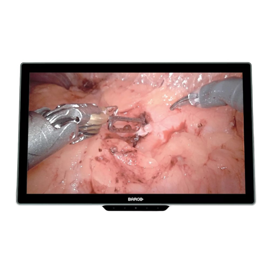
Welcome! Overview The MDSC-8527 is an Ultra High Definition (UHD) surgical display. Purpose-built for the operating room, the MDSC-8527 offers an easy-clean design, smart mechanics and the most detailed images in the operating room today. True-to-life colors in the surgical suite The MDSC-8527 has been designed for endoscopy imaging and the integrated operating room. - Page 6 Welcome! R5914634 /01 MDSC-8527...
-
Page 7: What's In The Box
1x external power supply • Mains cables The user guide is available in other languages on www.barco.com/support Keep your original packaging. It is designed for this display and is the ideal protection during transport. 1.2 About this user guide Overview This manual provides support to the user during the installation, set up and utilization of the MDSC-8527 display. -
Page 8: Product Overview
Welcome! 1.3 Product overview Overview Image 1–1 1. 5-key capacitive front keyboard By default only the stand-by key ( ) is visible. For keyboard activation please refer to “Front keyboard locking/unlocking”, page 20 2. Stand-by key and power status LED (see “Power status LED ”, page 21 for the behavior and different colors of the power status LED) -
Page 9: Connector Pin Assignments
Welcome! (**) The BNC SDI connectors match the characteristic impedance of 75 ohm cables. 1.4 Connector pin assignments 1.4.1 Power input connector Overview Image 1–3 1. +25 VDC 2. +25 VDC 3. GND 4. GND CAUTION: The ground and the shield connections on the power input connector have no Protective Earth function. -
Page 10: Usb Type A Connector
Welcome! 1.4.3 USB type A connector Overview Image 1–5 1. +5 VDC @ 1A max 2. Data - 3. Data + 4. GND 1.4.4 USB type B connector Overview Image 1–6 1. Data - 2. +5 VDC 3. Data + 4. -
Page 11: Hdmi Connector
Welcome! 1.4.6 HDMI connector Overview Image 1–8 1. T.M.D.S. Data2+ 2. T.M.D.S. Data2 Shield 3. T.M.D.S. Data2- 4. T.M.D.S. Data1+ 5. T.M.D.S. Data1 Shield 6. T.M.D.S. Data1- 7. T.M.D.S. Data0+ 8. T.M.D.S. Data0 Shield 9. T.M.D.S. Data0- 10. T.M.D.S. Clock+ 11. - Page 12 Welcome! R5914634 /01 MDSC-8527...
-
Page 13: Display Installation
Display installation R5914634 /01 MDSC-8527... -
Page 14: Cover Removal
Display installation 2.1 Cover removal To remove the connector cover 1. Gently press and hold the clips at the bottom right and left side of the connector cover. 2. Slide the cover downwards while holding the clips pressed. Either press the two clips at once, or press and release one side of the cover first and then press and release the other side. -
Page 15: Mdsc-8527 12Gp Version
Display installation 5. Connect the USB2.0 type B interface to a USB memory stick for in-field firmware updates. For more information, please refer to qualified service personnel. Image 2–2 DisplayPort VESA DP 1.2 certified cables for 5.4 Gbps HBR2 with a length of up to 3 m are recommended. -
Page 16: Power Supply Connection
Display installation Image 2–3 DisplayPort VESA DP 1.2 certified cables for 5.4 Gbps HBR2 with a length of up to 3 m are recommended. Premium certified HDMI 2.0 cables with a length of up to 3 m are recommended. Use 3G-SDI Belden 1694A cables with a length of up to 50 m. The video output must be enabled in the OSD menu (see “Video out”, page 38). -
Page 17: Cable Routing
Display installation Protective earth Earth the MDSC-8527 by connecting the protective earth pin to a grounded outlet by means of a yellow/green AWG18 wire (maximum admitted cable length according to national regulation requirements). Image 2–5 CAUTION: The display must be earthed. Potential equalization When potential equalization between the display and other devices is required then connect the potential equalization pin (POAG) to the potential equalization terminal of the equipment. -
Page 18: Vesa Mount Installation
Display installation 2.5 VESA mount installation To install the display on a VESA mounting solution The display can be attached to a VESA 100 mm arm or stand. Image 2–8 The VESA mounting holes at the back of the display are provided with M4-type blind fasteners to fix the VESA mounting plate. -
Page 19: Daily Operation
Daily operation R5914634 /01 MDSC-8527... -
Page 20: On/Off Switching
Daily operation 3.1 On/off switching The procedures below consider that DC power is supplied to the display. Please check the status of the power mode LED to verify that your display is supplied with DC power (see “Power status LED ”, page 21). -
Page 21: Power Status Led
Daily operation To unlock the front keyboard Two options are available to unlock the keyboard: With the front keyboard: 1. Press and hold (3-4 seconds) the key until the entire front keyboard starts blinking. 2. While the front keyboard is blinking, release the key again (within 2 seconds, to avoid a keyboard re- lock) and the front keyboard will be unlocked. - Page 22 Daily operation Image 3–2 When front menu functions have a submenu (eg. Main source selection), the submenu will be opened as new window on top of the front menu. The icon of the parent function and the currently selected option are shown in the top right corner of the new window.
-
Page 23: Osd Menu
Daily operation To activate the front menu With the front keyboard: 1. Unlock the front keyboard (see “Front keyboard locking/unlocking”, page 20). When the front keyboard is unlocked with the front keyboard itself, the front menu will automatically appear. When the front keyboard is unlocked with the rear keyboard, proceed to the next step. -
Page 24: Control Lock
Daily operation 4. Selector/Slider 5. Item value/setting Grayed out menu items are not available on the specific display version or configuration. To activate the OSD menu 1. Activate the front menu (see “Front menu ”, page 21). 2. Select the OSD main menu function ( ). As a result, the OSD main menu comes up. -
Page 25: Advanced Operation
Advanced operation Not all features described in the chapter “Advanced operation” are available. The features not available in specific software versions are shown on OSD menu in light-grey. R5914634 /01 MDSC-8527... -
Page 26: Picture Menu
Advanced operation 4.1 Picture menu 4.1.1 Profile About profiles To select a profile means to load a set of predefined video parameters like Brightness, Contrast, Saturation, Input selection (Primary & Secondary), Multi-image layout selection, etc. The user can modify the default video parameters associated to each profile and save the new parameters setting under the User 1, User 2 or User 3 profile. -
Page 27: Saturation
Advanced operation 4.1.4 Saturation To adjust the saturation level 1. Bring up the OSD main menu. 2. Navigate to the Picture menu. 3. Enter the Saturation submenu. The command bar Saturation is highlighted. 4. Set the saturation level as desired and confirm. 4.1.5 Color temperature About color temperature presets The available color temperature presets for your display are:... -
Page 28: Gamma
Advanced operation Combinations Color space / Gamma / Color temperature: – Color space = Native: All combinations of Color temperature and Gamma are possible. – Color space = ITU709: Gamma = 2.4, Color temperature = 6500K, Contrast = 50, Saturation = 50 fixed –... -
Page 29: Picture Advance Menu
Advanced operation 4.2 Picture advance menu 4.2.1 Input range About input range This command sets the video signal range. Suggest to set the input range according to the input signal range. The available input ranges are: • Full: Input range = 0–255 •... -
Page 30: Image Flip
Advanced operation The Pan function is only available when the Zoom function is selected. To pan the image 1. Bring up the OSD main menu. 2. Navigate to the Picture Advanced menu. 3. Enter the Pan submenu. The pan command bar is highlighted. 4. -
Page 31: Sdi Mode (12Gp Version Only)
Advanced operation To select the main source 1. Bring up the OSD main menu. 2. Navigate to the Input Select menu. 3. Enter the Main Source submenu. 4. Select one of the available main sources and confirm. 4.3.2 4K SDI mode (12GP version only) About 4K SDI mode The available 4K SDI modes for your display are: •... -
Page 32: Failover Input
Advanced operation 4.3.5 Failover input About failover input This function allows the display to automatically switch to a failover (backup) source in case the main source is missing. The display will automatically restore the main source once the signal is back. The available failover inputs for your display are: •... -
Page 33: Picture-By-Picture (Pbp)
Advanced operation 4.3.6 Picture-by-Picture (PBP) About Picture-by-Picture This function allows the display to show a second input source on the right side of the display. The Primary input (main source) is still displayed on the left half of the screen. The possible Picture-by-Picture combinations between the Primary input (main source) and the Secondary input (PBP image) is displayed in the following table. -
Page 34: Configuration Menu
Advanced operation Primary Secondary input input DP 1.2 SST HDMI-1 HDMI-2 3G-SDI 4K-SDI (**) DP 1.2 SST HDMI-1 HDMI-2 3G-SDI 4K-SDI (**) No PIP with DP 1.2 MST (**) MDSC-8527 12GP version Gamma and Color temperature for the PiP Source are always set to Native and 6500 K independently from the Transfer Function applied to the Primary input Source. -
Page 35: Language
Advanced operation 4.4.2 Language About languages The OSD menu of your display is available in multiple languages. To select the language 1. Bring up the OSD main menu. 2. Navigate to the Configuration menu. 3. Enter the Language submenu. 4. Select one of the available languages and confirm. 4.4.3 OSD time-out About OSD time-out The OSD menu can automatically close after a certain time of inactivity after the last selection was made. -
Page 36: Front Menu User Keys
Advanced operation The available profiles to save in your display are: • User 1 • User 2 • User 3 To save a profile 1. Bring up the OSD main menu. 2. Navigate to the Configuration menu. 3. Enter the Save Profile submenu. 4. -
Page 37: Display Name
Advanced operation To customize the name of an input source 1. Bring up the OSD main menu. 2. Navigate to the Configuration menu. 3. Enter the Input Signal name submenu. 4. Select one of the available input source and move right to the name definition area. 5. -
Page 38: Power Saving
Advanced operation 4.5.2 Power saving About power saving When the selected input(s) is (are) missing (main, 2nd and failover), this setting allows the display to switch off the backlight and enter a low power mode. As soon as the selected input(s) is (are) present again, the display will exit the power save mode and display the image. -
Page 39: Troubleshooting
Troubleshooting R5914634 /01 MDSC-8527... -
Page 40: Troubleshooting List
Troubleshooting 5.1 Troubleshooting list To diagnose a problem Problem description Action Black bars visible on upper and lower or left and This happens when the signal aspect ratio is right positions of the display. different from the one of the screen. This is not a display malfunction. -
Page 41: Important Information
Important information R5914634 /01 MDSC-8527... -
Page 42: Safety Information
Important information 6.1 Safety information General recommendations Read the safety and operating instructions before operating the device. Retain safety and operating instructions for future reference. Adhere to all warnings on the device and in the operating instructions manual. Follow all instructions for operation and use. Electrical Shock or Fire Hazard To prevent electric shock or fire hazard, do not remove cover. - Page 43 Important information Mission critical applications We strongly recommend there is a replacement monitor immediately available in mission critical applications. Use of Electrical Surgical Knives Provide as much distance as possible between the electrosurgical generator and other electronic equipment (such as monitors). An activated electrosurgical generator may cause interference with them. The interference can activate the OSD menu of the display and as such disrupt the functionality of the display.
- Page 44 Sufficient expertise is required for installing this equipment, especially to determine the strength of the wall for withstanding the display's weight. Be sure to entrust the attachment of this equipment to the wall to licensed contractors of Barco and pay adequate attention to safety during the installation and usage. •...
-
Page 45: Cybersecurity
Electronic Products ” (Also called RoHS of Chinese Mainland), the table below lists the names and contents of toxic and/or hazardous substances that Barco’s product may contain. The RoHS of Chinese Mainland is included in the MCV standard of the Ministry of Information Industry of China, in the section “Limit Requirements of toxic substances in Electronic Information Products”. - Page 46 Mainland, marked with the Environmental Friendly Use Period (EFUP) logo. The number inside the EFUP logo that Barco uses (please refer to the photo) is based on the “General guidelines of environment-friendly use period of electronic information products” of Chinese Mainland.
-
Page 47: Biological Hazard And Returns - Decommissioning
Important information This product meets the requirements of the “Management Rule on the Use Restriction of Hazardous Substances in Electrical and Electronic Products” and the “Management Catalogue for the Use Restriction of Hazardous Substances in Electrical and Electronic Products”. 绿色自我声明符合性标志可参见电子档文件 The green SDoC mark is visible in the digital version of this document. - Page 48 The manufacturing country of the product is indicated on the product label (“Made in …”). Importers contact information To find your local importer, contact one of Barco’s regional offices via the contact information provided on our website (www.barco.com). Factory address Fimi S.r.l., Via Saul Banfi 1, 21047 Saronno, VA, Italy...
-
Page 49: Emc Notice
Important information Canadian notice CAN ICES-003 (B) / NMB-003(B) UKCA compliance UK Responsible Person (UKRP): Barco UK Ltd, Building 329, Doncastle Road, Bracknell RG12 8PE, Berkshire, United Kingdom 6.6 EMC notice General information This device is for use in professional healthcare facility environments only. - Page 50 Important information • Increase the separation between the equipment and receiver. • Connect the equipment into an outlet on a circuit different from that to which the receiver is connected. • Consult the dealer or an experienced technician for help. Electromagnetic immunity The MDSC-8527 is intended for use in the electromagnetic environment specified below.
-
Page 51: Cleaning Instructions
Important information Immunity to RF wireless communications equipment Test Immunity Maximum Distance frequency Band (MHz) test level (V/ Service Modulation power (W) (MHz) 380 – 390 TETRA 400 Pulse modulation 18 Hz 430 – 470 GMRS 460, FM ± 5 kHz FRS 460 deviation 1 kHz sine... -
Page 52: Explanation Of Symbols
Important information • Peroxide hydrogen 10% • Ethanol 15% (e.g. Tanet interior) When selecting an alternative cleaning/disinfecting product, it is recommended to always identify the active ingredients. In case of doubt about a certain cleaning product, use plain water. Do not use any of the following products: •... - Page 53 Important information Indicates the device is approved according to the UL regulations for Canada and US. E346057 Medical –general medical equipment as to electrical shocks, fire and mechanical hazards only in accordance with standards: ANSI/AAMI ES 60601-1:2005/(R)2012; CSA CAN/CSA-C22.2 NO. 60601-1:14; Also certified UL60950-1 (E92049). E346057 Also Certified UL60950-1 E92049...
- Page 54 Important information Indicates the device meets the requirements of the UK MDR 2002 (as amended). Indicates the USB connectors on the device. Indicates the DisplayPort connectors on the device. Indicates the legal manufacturer. Indicates the manufacturing date. Indicates the entity importing the medical device into the locale. Indicates the temperature limitations for the device to safely operate within specs.
- Page 55 Important information Consult the Instruction For Use on website address that is provided as eIFU indicator. eIFU indicator Indicates this device must not be thrown in the trash but must be recycled, according to the European WEEE (Waste Electrical and Electronic Equipment) directive. Indicates Direct Current (DC).
-
Page 56: Legal Disclaimer
Barco software products are the property of Barco. They are distributed under copyright by Barco NV or Barco Inc., for use only under the specific terms of a software license agreement between Barco NV or Barco Inc. and the licensee. No other use, duplication, or disclosure of a Barco software product, in any form, is authorized. - Page 57 Important information Resolution 3840 x 2160 pixels Pixel pitch 0.155 mm Color support 1 billion (10 bit color depth) Color gamut Native: 88% NTSC Color calibration ITU-709, DCI-P3, BT.2020 (BT.2020 reproducible colors are within the limit of the LCD panel) Viewing angle 178°...
- Page 58 Important information Display features User-programmable function keys, Picture-in-Picture, Picture-by-Picture, Image Mirror and Rotation, Zoom, Pan, Failover mode, User profiles, High quality upscaling from SD / FHD input to UHD, FW upload from memory stick Power consumption MDSC- Max. 90W / 25V ± 10% 8527 SSTP Low power mode: <...
- Page 59 UL 60950-1, 2nd Edition (to make the equivalence with NOM-019) * Some of the listed certifications may still be pending. For the actual list of applicable certifications, please refer to the product page on www.barco. or see the certification marks on the product label of your display. Protection level...
- Page 60 Important information UHD/4K timings Format HDMI DP 1.2 SST DP 1.2 MST 3840x2160@25.00Hz 3840x2160@30.00Hz 3840x2160@50.00Hz 3840x2160@60.00Hz Available only with 12GP display version Square Division Sample-interleave Format SDI std (SQD) (SI) 3840x2160@50.00Hz Quad-link 3840x2160@59.94Hz Quad-link 3840x2160@60.00Hz Quad-link 3840x2160@25.00Hz Single-link (6G-SDI) 3840x2160@29.97Hz Single-link (6G-SDI) 3840x2160@30.00Hz Single-link (6G-SDI)
- Page 61 Important information Dimensions 74.5 278.5 M4 - 4x 598.6 (VIEWING AREA) Image 6–1 R5914634 /01 MDSC-8527...
- Page 62 Important information R5914634 /01 MDSC-8527...
- Page 64 Barco NV President Kennedypark 35 8500 Kortrijk Belgium R5914634 /01 | 2022-03-17 www.barco.com...
Need help?
Do you have a question about the MDSC-8527 Series and is the answer not in the manual?
Questions and answers