Table of Contents
Advertisement
Quick Links
Advertisement
Table of Contents

Related Manuals for Barco MDSC-8358 Series


Summary of Contents for Barco MDSC-8358 Series
-
Page 1: User Guide
MDSC-8358 User Guide MDSC-8358 RL MDSC-8358 RLG ENABLING BRIGHT OUTCOMES... - Page 2 Barco NV Beneluxpark 21, 8500 Kortrijk, Belgium www.barco.com/en/support www.barco.com Registered office: Barco NV President Kennedypark 35, 8500 Kortrijk, Belgium www.barco.com/en/support www.barco.com...
-
Page 3: Table Of Contents
Table of contents 1 Welcome!.......................................... 5 About the product....................................6 What's in the box ....................................6 About this user guide ..................................6 2 Parts, controls and connectors..............................9 Front view......................................10 Rear view......................................11 Connector view ....................................11 Connector pin assignments ..............................12 2.4.1 DVI–D single link / dual link connector ......................12 2.4.2 RS232 connector ................................13 3 Display installation....................................15... - Page 4 5.7.2 Failover input.................................28 OSD setting menu ..................................29 5.8.1 Time-out OSD ................................29 5.8.2 OSD menu lock ................................29 Setup menu......................................29 6 Important information..................................31 Safety information...................................32 Environmental information.................................34 Biological hazard and returns ..............................36 Cleaning and disinfection ................................37 Regulatory compliance information ............................37 EMC notice ......................................38 Explanation of symbols................................41 Legal disclaimer....................................44 Technical specifications................................45...
-
Page 5: Welcome
Welcome! K5902150 (451920612554) /03 MDSC-8358... -
Page 6: About The Product
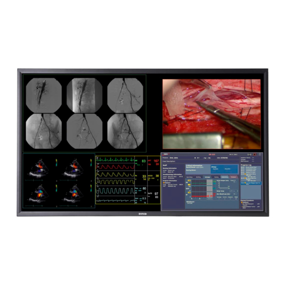
1.1 About the product Overview The Barco Medical Grade MDSC-8358 series are color high resolution liquid crystal displays especially designed for medical imaging applications. The MDSC-8358 is a 58” Color Flat Panel Display, intended to replace typical multi-monitor arrays in medical applications, whenever a large display is needed in addition to high resolution, while offering the same good rendering in greyscale medical imaging thanks to the DICOM conformance. - Page 7 Welcome! Warnings, cautions, notes and tips There are four levels of precautionary or advisory statements that may be used in this user guide. In descending order of importance, they are: WARNING: Describes hazards or dangers that might result in personal injury or death. CAUTION: Describes hazards that could damage the product.
- Page 8 Welcome! K5902150 (451920612554) /03 MDSC-8358...
-
Page 9: Parts, Controls And Connectors
Parts, controls and connectors K5902150 (451920612554) /03 MDSC-8358... -
Page 10: Front View
Parts, controls and connectors 2.1 Front view Overview Image 2-1 Power On/Off Enter key Down key Up key Esc key A 5-key keypad is located on the bottom of the display. K5902150 (451920612554) /03 MDSC-8358... -
Page 11: Rear View
Parts, controls and connectors 2.2 Rear view Overview Image 2-2 VESA mount screw holes Connector location 2.3 Connector view Connectors 6 10 6 10 Image 2-3 Additional protective earth pin Input power connector RS-232 connector Switch (between RS-232 & Ethernet) Ethernet connector for monitor remote control DVI-D single link / dual link connector (*) +5V out connector... -
Page 12: Connector Pin Assignments
Parts, controls and connectors DVI splitter input connector (*) 4 DVI connectors, numbered from 1 to 4 from right to left; all connectors must be installed when in SL mode; DVIs 1 & 3 or 2 & 4 must be installed when in DL mode. The 5V connections are available with the specific purpose to power an external DVI extender. -
Page 13: Rs232 Connector
Parts, controls and connectors 2.4.2 RS232 connector Overview Image 2-5 Function Not connected Rx (driven by host) Tx (driven by display) Not connected Ground Not connected Not connected Not connected Not connected K5902150 (451920612554) /03 MDSC-8358... - Page 14 Parts, controls and connectors K5902150 (451920612554) /03 MDSC-8358...
-
Page 15: Display Installation
Display installation K5902150 (451920612554) /03 MDSC-8358... -
Page 16: Hoist Bracket Installation
Display installation 3.1 Hoist bracket installation WARNING: Two brackets are provided in the accessory kit to be used for service personal only. WARNING: The hoist brackets are intended to be used during the monitor's installation phase only. To mount and use the hoist bracket to the display Mount the brackets to the display using the screws provided in the accessory kit. - Page 17 Display installation After transportation, you can remove the brackets and the 8 mounting holes can be closed, either with 8 plastic caps (version without the protection glass) or using the same screws adding the respective o-ring (version with the protection glass). K5902150 (451920612554) /03 MDSC-8358...
-
Page 18: Vesa Mount Installation
Display installation 3.2 VESA mount installation Overview The display supports mounting arm & stands according to the VESA 400 mm standard. CAUTION: Use an arm that is in compliance with VESA requirements. CAUTION: The monitor VESA interface has been designed for a safety factor 6 (to support 6 times the monitor weight). -
Page 19: Video Input Connection
Display installation Image 3-1 3.3 Video input connection WARNING: When the display is assembled in the medical system, take care of the anchorage of all cables, to avoid unwanted detachment. To connect the video inputs Connect the available display(s) to the corresponding video input(s) using the appropriate video cable(s). Image 3-2 K5902150 (451920612554) /03 MDSC-8358... -
Page 20: Video Output Connection
Display installation Overview possible inputs DisplayPort DVI splitter 3.4 Video output connection WARNING: When the display is assembled in the medical system, take care of the anchorage of all cables, to avoid unwanted detachment. To connect the video outputs Connect the available display(s) to the corresponding video output(s) using the appropriate video cable(s). Image 3-3 Overview possible outputs DVI splitter... -
Page 21: Daily Operation
Daily operation K5902150 (451920612554) /03 MDSC-8358... -
Page 22: On/Off Switching
Daily operation 4.1 On/Off switching About power management: The display has 2 keys: • Main power switch (to switch of all power to the display). • Push button to enter/exit the Power Down Mode. The display can go in three different statuses: •... -
Page 23: Osd Menu Activation
Daily operation brightness ranges from 40 cd/m² to 600 cd/m² in DICOM modes and from 5% (about 90 cd/m²) to 100% (about 700 cd/m²) in COLOR modes. 4.4 OSD menu activation To activate the OSD menu If not already done so, switch on the display. Touch the Enter key. - Page 24 Daily operation Enter the password by using the four right keys of the keyboard, you can label the four keys as 1, 2, 3 and 4 (from left to right). So, if i.e. keycode is '4444', it means you have to press four time the Esc key. If the inserted password is not correct, the following message appears on the screen.
-
Page 25: Advanced Operation
Advanced operation K5902150 (451920612554) /03 MDSC-8358... -
Page 26: Product Info
Advanced operation 5.1 Product info About product info The available information items for your display are: • HWREL: Hardware release • FWREL: Firmware release • S/N: Serial number To view the product info Bring up the OSD main menu. Navigate to the Product info menu. Enter the Product info submenu. -
Page 27: Transfer Function
Advanced operation 5.4 Transfer function About transfer function There are different transfer function possibilities: • Native: the transfer function is transparent (no correction is applied). • DICOM (Factory): The output curve follows the DICOM transfer function and is automatically adapted to the current brightness. -
Page 28: Input Channel Selection
Advanced operation 5.7 Input channel selection 5.7.1 Input channel menu About input channel menu Possibility to select the following inputs: • DISPLAYPORT • DISPLAYPORT FAILOVER • DVI 1 • DVI 2 • DVI 3 • DVI 4 • 4 DVI Single Link •... -
Page 29: Osd Setting Menu
Advanced operation 5.8 OSD setting menu 5.8.1 Time-out OSD About time-out OSD When the OSD menu is displayed and no key is pressed, it will disappear after the time set in this menu. It is possible to choose among the following values: 10”, 20”, 30”, 45”, 60”, 90” or disable. When the time-out is set to disable, the OSD menu won't disappear until the user exit the OSD menu pressing the Esc key. - Page 30 Advanced operation To select the setup: Bring up the OSD main menu. Navigate to the Setup menu. Enter the Setup submenu. Select one of the available profiles and confirm. K5902150 (451920612554) /03 MDSC-8358...
-
Page 31: Important Information
Important information K5902150 (451920612554) /03 MDSC-8358... -
Page 32: Safety Information
Important information 6.1 Safety information General recommendations Read the safety and operating instructions before operating the device. Retain safety and operating instructions for future reference. Adhere to all warnings on the device and in the operating instructions manual. Follow all instructions for operation and use. Electrical Shock or Fire Hazard To prevent electric shock or fire hazard, do not remove cover. - Page 33 Important information Mission critical applications We strongly recommend there is a replacement monitor immediately available in mission critical applications. Use of Electrical Surgical Knives Provide as much distance as possible between the electrosurgical generator and other electronic equipment (such as monitors). An activated electrosurgical generator may cause interference with them. The interference can activate the OSD menu of the display and as such disrupt the functionality of the display.
-
Page 34: Environmental Information
Sufficient expertise is required for installing this equipment, especially to determine the strength of the wall for withstanding the display's weight. Be sure to entrust the attachment of this equipment to the wall to licensed contractors of Barco and pay adequate attention to safety during the installation and usage. •... - Page 35 Electronic Products ” (Also called RoHS of Chinese Mainland), the table below lists the names and contents of toxic and/or hazardous substances that Barco’s product may contain. The RoHS of Chinese Mainland is included in the MCV standard of the Ministry of Information Industry of China, in the section “Limit Requirements of toxic substances in Electronic Information Products”.
-
Page 36: Biological Hazard And Returns
Mainland, marked with the Environmental Friendly Use Period (EFUP) logo. The number inside the EFUP logo that Barco uses (please refer to the photo) is based on the “General guidelines of environment-friendly use period of electronic information products” of Chinese Mainland. -
Page 37: Cleaning And Disinfection
Important information Therefore use of this device in such environments is at the exclusive risk of Customer. In case this device is used where potential biological contamination cannot be excluded. Customer shall implement the decontamination process as defined in the latest edition of the ANSI/AAMI ST35 standard on each single failed Product that is returned for servicing, repair, reworking or failure investigation to Seller (or to the Authorized Service Provider). -
Page 38: Emc Notice
The manufacturing country of the product is indicated on the product label (“Made in …”). Importers contact information To find your local importer, contact one of Barco’s regional offices via the contact information provided on our website (www.barco.com). FCC Class A This equipment has been tested and found to comply with the limits of a class A digital device, pursuant to Part 15 of the FCC rules. - Page 39 Important information Interference can be determined by turning the equipment off and on. If this equipment does cause harmful interference to, or suffer from harmful interference of, surrounding equipment, the user is encouraged to try to correct the interference by one or more of the following measures: •...
- Page 40 Important information IEC 60601-1-2 4 edition Electromagnetic (2014) Immunity test Compliance level environment – guidance Test levels Power frequency (50/60 30 A/m 30 A/m Power frequency Hz) magnetic field magnetic fields should be at levels characteristic of a IEC 61000-4-8 typical location in a typical commercial or hospital environment.
-
Page 41: Explanation Of Symbols
Important information These guidelines may not apply in all situations. Electromagnetic propagation is affected by absorption and reflection from structures, objects and people. Recommended separation distance The MDSC-8358 is intended for use in an electromagnetic environment in which radiated RF disturbances are controlled. - Page 42 Important information Indicates the device is approved according to the UL Demko regulations. Indicates the device is approved according to the CCC regulations. Indicates the device is approved according to the VCCI regulations. Indicates the device is approved according to the KC regulations. Indicates the device is approved according to the BSMI regulations.
- Page 43 Important information Indicates the temperature limitations for the device to safely operate within specs. Indicates this is a Medical Device. Indicates the device serial number. Indicates the device part number or catalogue number. Indicates the Unique Device Identifier. Warning: dangerous voltage Caution Consult the Instructions For Use.
-
Page 44: Legal Disclaimer
Barco software products are the property of Barco. They are distributed under copyright by Barco NV or Barco Inc., for use only under the specific terms of a software license agreement between Barco NV or Barco Inc. and the licensee. No other use, duplication, or disclosure of a Barco software product, in any form, is authorized. -
Page 45: Technical Specifications
This document is copyrighted. All rights are reserved. Neither this document, nor any part of it, may be reproduced or copied in any form or by any means - graphical, electronic, or mechanical including photocopying, taping or information storage and retrieval systems - without written permission of Barco. © 2020 Barco NV all rights reserved. - Page 46 Important information Screen protection Protective, non-reflective glass cover Recommended modalities Endoscopy, Laparoscopy, PACS, PM, US, CT, MR Certifications CE (Medical Device Class I) IEC 60601-1-2 (2014) EN 60601-1-2 (2015) IEC 60950-1:2005 +A1:2009 +A2:2013 (Second Edition) IEC 60601-1:2005 +CORR. 1:2006 +CORR.2:2007 +A1:2012 (Edition 3.1) EN 60601-1:2006 +A1:2013 +A12:2014 ANSI/AAMI ES60601-1: A1:2012 +C1:2009/(R)2012 +A2:2010/(R)2012 CAN/CSA-C22.2 NO.
- Page 47 Important information Dimensions 1318.5 459.25 459.25 Image 6-1 K5902150 (451920612554) /03 MDSC-8358...
-
Page 48: Open Source License Information
A list of the Open Source Software components used is available in the applicable EULA, through the “My Barco” section of the Barco website or through other (online) means. Copyright on each Open Source Software component belongs to the respective initial copyright holder, each additional contributor and/or their respective assignee(s), as may be identified in the respective Open Source Software documentation, source code, README file, or otherwise. - Page 49 Barco whatsoever. You further acknowledge that any such additions, changes or modifications may impair the ability of Barco – at Barco’s sole discretion - to continue to provide service, warranties, software updates, fixes, maintenance, access or such similar abilities, without any recourse or claim towards Barco whatsoever.
- Page 50 Important information K5902150 (451920612554) /03 MDSC-8358...
-
Page 51: Appendix A
Appendix A K5902150 (451920612554) /03 MDSC-8358... -
Page 52: Rs-232 Protocol
Appendix A 7.1 RS-232 protocol About RS-232 protocol The communication protocol of the monitor is based upon user oriented commands and factory oriented commands. The following description is related to the user oriented commands and is based on the MDSC- 8358 monitors user commands. - Page 53 Appendix A (character) Current Transfer Function 0 (zero) NATIVE DICOM GAMMA 1 GAMMA 2 the character O in the command sequence is the letter “o” in uppercase. 2b) Set Transfer Function: PC > monitor: <ESC> O (character) monitor > PC: <ACK> where (character) has the following meaning: (character) Current Transfer Function...
- Page 54 Appendix A 4c) Keylock code: PC > monitor: <ESC> v???? monitor > PC: <ACK> where “?” is a number between 1 and 4 which codifies the key according to the following table: “?” character ▼ ▲ ☼– ☼+ 5) FPGA Release: PC >...
- Page 55 Appendix A K5902150 (451920612554) /03 MDSC-8358...
- Page 56 Barco NV President Kennedypark 35 8500 Kortrijk Belgium K5902150 (451920612554) /03 | 2020-02-27 Barco NV | Beneluxpark 21, 8500 Kortrijk, Belgium Registered office: Barco NV | President Kennedypark 35, 8500 Kortrijk, Belgium www.barco.com...
Need help?
Do you have a question about the MDSC-8358 Series and is the answer not in the manual?
Questions and answers