Table of Contents
Advertisement
Quick Links
OPERATOR'S MANUAL
REAR ARM-TYPE MOWER
KWT 550 (E, EP)
KWT 650 (E, EP)
KWT 651 (E,EP)
MOWING ADAPTERS
KW 110
KW 111
KW 125
KW 126
KW 140
KW 141
Poland, 16-060 Zabłudów, ul. Trawiasta 1
CAMEL 900 (EP)
KOLIBER 400 (E, EP)
KOLIBER 450 (E, EP)
Original manual
SaMASZ Sp. z o.o.
Established – 1984
NIP PL-966-159-29-76
tel. (+48) (85) 664 70 31
fax (+48) (85) 664 70 41
e-mail: samasz@samasz.pl
LAMA 101 P
LAMA 120 P
LAMA 120
LAMA 140
LAMA 121
LAMA 141
LAMA 121 HD
EDITION NO. 11
www.samasz.pl
IN347EN011
2016.12.22
Advertisement
Table of Contents

Subscribe to Our Youtube Channel
Related Manuals for SaMASZ KWT 550


Summary of Contents for SaMASZ KWT 550
- Page 1 (+48) (85) 664 70 31 fax (+48) (85) 664 70 41 e-mail: samasz@samasz.pl www.samasz.pl OPERATOR'S MANUAL REAR ARM-TYPE MOWER KWT 550 (E, EP) CAMEL 900 (EP) KWT 650 (E, EP) KOLIBER 400 (E, EP) KWT 651 (E,EP) KOLIBER 450 (E, EP)
- Page 2 WARNING: Keep this manual for future use. We congratulate you on the purchase of your new SaMASZ machine and wish you much pleasure and the very best experience resulting from its operation. We congratulate you on the purchase of your new SaMASZ tedder and wish you much pleasure and the very best work results through the years to come.
-
Page 3: Table Of Contents
Operator's manual Flail head Table of contents page IDENTIFYING THE MACHINE ......................2 INTRODUCTION ............................ 3 PROPER USE ............................3 3.1. Technical data ............................... 4 3.2. Design and working principle ..........................9 3.2.1. Arm ................................. 9 3.2.2. Flail head ............................... 14 3.2.3. -
Page 4: Identifying The Machine
Data plate is attached firmly on both long boom and flail head and placed as provided on Fig. 1, Fig. 2 and Fig. 3. Fig. 1. Data plate placement on arm KWT 550/650 Fig. 2. Data plate placement on arm KOLIBER 400 Fig. -
Page 5: Introduction
Moreover the mower can be used to trim hedges both in vertical and in horizontal position. The arm can be additionally equipped with adapters offered by the SaMASZ co. Arms work properly on grass (and other plants) with height up to 1.0 m. Heads are designed for shredding cut tree branches, mowing weeds, shrubs and grass. -
Page 6: Technical Data
Flail head 3.1. Technical data SaMASZ manufactured extension arms are adjusted to operate with numerous flail heads and feature the following parameters (Tab. 1, Tab.2, Tab. 3, Tab. 4): Tab. 1. Technical characteristics of extension arms Arm type (without flail head) - Page 7 Operator's manual Flail head Tab. 2. Technical data for flail heads KW Flail head type KW 110 KW 111 KW 125 KW 126 KW 140 KW 141 Operating width [m] 1,10 1,10 1,25 1,25 1,40 1,40 Number of knives [pcs] Max.
- Page 8 KWT 550 / Lama 120 KWT 550 / Lama 140 KWT 550 / Lama 121 KWT 550 / Lama 141 KWT 550 / Lama 120 P KWT 550 / Lama 101 P KWT 550 / Lama 121 HD KWT 650 / KW 110...
- Page 9 Operator's manual Flail head 45° Fig. 4. Scheme of operating reach of extension arm with flail head with marking type: KWT 550/650, KWT 651 and CAMEL 900 - 7 -...
- Page 10 Operator's manual Flail head Fig. 5. Scheme of operating reach of extension arm with flail head with marking type: KOLIBER 400 - 8 -...
-
Page 11: Design And Working Principle
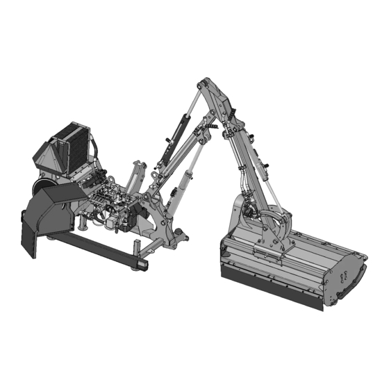
Operator's manual Flail head Fig. 6. Operating reach of extension arm KWT 651 E and KWT 651 EP with flail head 3.2. Design and working principle 3.2.1. Arm Extension arm comprises basic assemblies shown in Fig. 7 – Fig. 11. 1- Lifting and lowering cylinder 10- Multiplier 2- Lifting and lowering cylinder... - Page 12 Operator's manual Flail head Fig. 7. Overview of Koliber extension arm Fig. 8. Overview of CAMEL extension arm - 10 -...
- Page 13 Operator's manual Flail head Fig. 9. Overview of KWT 550 extension arm Fig. 10. Overview of KWT 650 extension arm - 11 -...
- Page 14 Operator's manual Flail head Fig. 11. Overview of KWT 651 extension arm Extension arm is equipped with independent hydraulics with oil cooler and oil tank (9). Rotor’s drive and arm control is possible owing to own hydraulic pumps assembly driven by multiplier (10), transmitter’s shaft without coupling and tractor’s PTO.
- Page 15 Fig. 12. Machine's control panel with option: a) mechanical (KWT 550/560, CAMEL 900, KOLIBER 400/450), b) electrical (KOLIBER 400E/450E), c) electrical (KWT 550 E, KWT 650 E, KWT 651 E, KOLIBER 400EP/450EP), d) electrical proportional (KWT 550 EP, KWT 650 EP, KWT 651 EP, CAMEL...
-
Page 16: Flail Head
Operator's manual Flail head Fig. 13. Hydraulics with oil tank and KWT mower radiator Fig. 14. Multipliers with hydraulic pumps Fig. 15. Machine suspension: 18 - Protective and tensioning strands, 19 - Mounting points on tractor's 3-point linkage 3.2.2. Flail head All flail heads (KW, Lama) adjusted to operate with extension arms have similar construction. - Page 17 Operator's manual Flail head Operating assembly of extension arm is a flail head (6), which comprises flail bar (20) with flail knives (21) for different purposes (item 6.4), screwed with mounting bolts (knife type depends of kind of surface mowed (grass, bushes, hay, cornstalks). Flail shaft (20) of flail head is driven by hydraulic engine (23).
- Page 18 Operator's manual Flail head Lama 120P mowing head with ejection comprises flail shaft (20) with flail knives (21) mounted with mounting screws. Alike KW and Lama heads, the flail shaft (20) of mowing head is driven by hydraulic motor (23). Ground following shaft (22) has mowing height adjustment function (Section 6.3).
-
Page 19: Mounting Flail Heads Lama 121 And Lama 141
1. The basic is a rigid fitting, simple and light, attached to an extension arm with 6 screws M14 (SaMASZ-standard). 2. Swivel fitting, mounted with 6 screws M14 (SaMASZ-standard) to an extension arm, enables the head to be swiveled every 15° in 4 positions. -
Page 20: Characteristics Of Hydraulics Of Arm
(8) there is sweep valve (7) mounted to protect the machine's arms from getting overloaded (Fig. 21) – applies only to KWT 550, KWT 650 and Camel 900. Koliber 400 and Koliber 450 instead of gauge plate cylinder (8) both have overload breaker. Hydraulic cylinders (8-11) with throttle choke valves (12) control the arm. - Page 21 Operator's manual Flail head (Subject: KWT 650 E/EP, Camel 900 and Camel 900 EP) Geared pumps power two independent circuits: machine's drive circuit with capacity of 50 l/min and hydraulic cylinders' drive circuit with capacity of 11 l/min (22 l/min. - EP). In machine's drive circuits wires have ∅16 mm diameter, while in cylinders' control circuit ∅10 mm.
-
Page 22: Standard Equipment And Spare Parts
50 hours. PTO shaft shall also be lubricated prior to and after period of longer idleness. PTO shafts of other brands with equivalent technical parameters may be used on the SaMASZ permission. 3.4.1. Flails applied in mowing heads In order to ensure proper operation of mowing head, if excessively worn flails should be replaced. - Page 23 Operator's manual Flail head Flail knives LAMA KNIFE TYPE III Application: grass, shoots, stalks, Option ‒ shrubs, remnants after trimming, hay KNIFE TYPE IV Application: grass, shoots, stalks, Option ‒ shrubs, remnants after trimming, hay Standard in KNIFE TYPE V Standard in KW 111, KW 126, Application:...
-
Page 24: Safety Advice
Operator's manual Flail head SAFETY ADVICE 4.1. Safety rules and regulations Front axis of the tractor should be well weighted to keep the balance. If need be, use front wheel weights. Any operation with the hydraulic lift lever should be conducted from the operator's seat; DO NOT move the lever from outside of the tractor. -
Page 25: Conditions Of Mounting Machine On Tractor
Operator's manual Flail head If any part of the machine needs to be replaced, use only genuine spare parts according to spare part list. Pay particular attention to PTO shaft guards and machine and tractor spline shaft guards. Never operate with damaged guards. The machine should be stored under roof and in manner preventing animals and people to be injured. -
Page 26: Putting The Machine Onto Another Vehicle For Transport
Operator's manual Flail head 4.3.1. Putting the machine onto another vehicle for transport Both the carrier and the driver shall be responsible for the machine transport safety. Any equipment and parts must be properly secured for transport. To put the machine onto another vehicle safely, please follow these rules: it is recommended to transport extension arms using a forklift truck (Fig. -
Page 27: Working Parts
Operator's manual Flail head Fig. 25. Location of centre of gravity for flail heads Tab. 6. Location of centre of gravity for flail heads Type Dimension [mm] KW 110 KW 111 KW 125 KW 126 KW 140 KW 141 Type Dimension LAMA LAMA... -
Page 28: Residual Risk
Operator's manual Flail head Scotch tape shall never be used to repair damaged hydraulic hoses. When connecting hydraulic hoses to tractor hydraulic connectors make sure, that either tractor or machine hydraulics are pressure free. When operating hydraulic unit, always wear protective gloves and eyewear. Leaking hydraulic oil under pressure (16 MPa) may permeate through the skin and cause an infection. -
Page 29: Residual Risk Assessment
Operator's manual Flail head The following bans should be borne in mind when operating the machine: do clean impurities, make any adjustments or repairs when the machine is in operating mode, never change the sequence of operation and maintenance works specified in the operator's manual, never operate the machine when it is not in working condition or has safety guards damaged, never get your limbs close to rotating parts of the machine,... -
Page 30: Ohp Recommendations During Operation - Remarks For Operator
Driver – Your safety depends of Your imagination and following the rules. The SaMASZ company has not conducted any tests on static. Therefore the user should pay special attention and be careful and potentially following his own efforts determine a slope parameter which allows for proper set operation. - Page 31 Operator's manual Flail head N-06 N-07 N-09 N-11 Caution: pulling-in Keep away from the Caution: rotor Lubrication points parts machine for a safe distance N-23 N-28 N-29 N-40 Transport holder for Pay attention to power- On special order moving lines the machine N-49 N-50...
- Page 32 Operator's manual Flail head CAUTION: Any assembly used for the machine repair should hold all warning decals provided by the manufacturer. N-134 N-11 N-03 N-04 N-117 N-171 N-40 N-167 N-169 N-01 ; N-02 N-03 ; N-04 N-11 N-06 ; N-07 N-09 ;...
-
Page 33: Operation
Flail head OPERATION CAUTION: During storing of the machines in company SaMASZ the cylinders are protected by special grease in order to secure them against weather which may cause their premature wear. Before starting the operation excess grease should be removed from the cylinders. - Page 34 (at street side). Warning plate with white and red stripes equipped with a light on right side should also be mounted. Fig. 29. Actuator hydraulic lock and choke valve in extension arms KWT 550/650, CAMEL 900, Koliber 400/450 CAUTION: For transportation of outrigger close valve (Z) (Fig.
- Page 35 Operator's manual Flail head Fig. 30. Safety valve for transportation of outriggers KWT 550E/650E/651E CAUTION: For transport purposes protect outrigger from getting rotated by means of a pin (Fig. 31). Fig. 31. Protecting outrigger from getting rotated CAUTION: Do not drive machine on public roads, if its transport height is more than 4 m (transport height should be lowered with tractor’s links when transported).
-
Page 36: Mounting Pto Shaft
(all knives must be of the same type, have the same weight, if need be, knife should be replaced with new one in pairs with the same SaMASZ manufacture weight),... -
Page 37: Operation
Operator's manual Flail head tightness in hydraulics, rotation ease of flail rotor, warning signs for needs of driving on public road (warning triangle at the tractor's rear, warning plates painted in skew white and red stripes and yellow flashing light), open oil shut-off valve, engage front PTO drive, inserting multiplier with pumps into the drive, set the machine in working position respectively for each location mowed,... - Page 38 Operator's manual Flail head Fig. 36. Mowing behind protection barriers with Fig. 37. Mowing behind protection barriers with CAMEL 900 Fig. 38. Working position for KWT 651 CAUTION: When maneuvering the operating head pay attention so as not to hit it against a tractor or the extension arm (Fig.
-
Page 39: Operating Control Panel
Operator's manual Flail head 5.5.1. Operating control panel Tilting with the machine's arms is performed with use of hydraulic cylinders controlled from control panel located in the tractor's cabin. On the panel there is the machine diagram placed with numbering of each cylinder (Fig. 41) and corresponding control levers. Fig. - Page 40 Operator's manual Flail head floating left right Lever A Lever B Joystick C Lever D Fig. 41. Control pictograms Fig. 42. Lock of direction change a) right rears (work), b) left rears CAUTION: Sudden changing direction of rears may lead to damaging hydraulics. Left rears can be turned on as soon as hydraulic engine's rears are completely stopped.
- Page 41 Operator's manual Flail head Control panel with electrical controlling Controlling KOLIBER E extension arms and operating head is possible thanks to lever (I) as well as (J) control panel Fig. 43, marked with corresponding labels: E – power on/off; F – hydraulic engine (22) on/off; - position „0”...
- Page 42 Flail head III. Panel with electrical control (semi-proportional) Proportional controlling set for extension arms KWT 550 E, KWT 650 , KWT 651E, Koliber 400EP, Koliber 450EP and Camel 900 EP comprises the following elements as provided on Fig. 44: A. Control joystick, B.
- Page 43 Operator's manual Flail head 2. Control switch off. To turn control off, hold button (2) for around 2 seconds. Turning control on is signaled by a diode (3), which turns to steady light. 3. Diode signals turning both power and control on. 4.
- Page 44 Operator's manual Flail head Description of decal on manner of controlling arm Joystick’s motion to the right lifts the second Joystick’s forward motion extension arm up. lowers the first arm. Joystick’s motion to the left lowers the second extension arm. Joystick’s backwards Pushing joystick’s button 2 and motion lifts the first arm...
- Page 45 Operator's manual Flail head Fig. 48. Proportional control description Proportional control description: 1) Moving joystick in directions as marked in Fig. 48 as (1), enables control of the main extension arm. 2) Moving joystick in directions (2), enables control of the other extension arm. 3) Unloading function switch on button.
-
Page 46: Basic Information On Mowing
Operator's manual Flail head 5.5.2. Basic information on mowing Basing on long-term experience, in order to ensure the machine damage-free operation, it is recommended to engage a pilot in front of the mower to mark any obstacle. When traversing the road, pedestrian crossing or any other obstacle, the machine must be lifted with use of cylinder 4. -
Page 47: Mounting Flail Heads
Operator's manual Flail head 6.2. Mounting flail heads Coupling Lama 121/ 141 mowing heads is significantly facilitated owing to application of mountings. Mountings such as: basic mounting (Fig. 20, item 1), rotary mounting (item 2), hydraulic turntable (item 3) are normally bolted to extension arm with 6 bolts. Hydraulic turntable can be attached to mowing heads. - Page 48 Operator's manual Flail head Hydraulic turntable is controlled with a special hydraulic motor (Fig. 52), which is powered directly from the tractor's hydraulics. For this purpose: connect two hydraulic push-in fittings to the tractor's hydraulics, moving an appropriate control lever for distributor in the tractor, rotate the mowing head and set it in the desired position, if the head rotation is performed too fast, throttle the oil flow with throttle valves (3) located just behind hydraulic push-in fittings.
-
Page 49: Adjusting Flail Head Mowing Height
Operator's manual Flail head 6.3. Adjusting flail head mowing height In order to set the desired mowing height, the following should be performed: preset mowing height is approx. 3 cm (Fig. 54). Mowing height modification for 5; 7.5 cm respectively can be obtained by loosening adapting shaft mounting bolts, what is shown on Fig. -
Page 50: Operating Hydraulics
PREMIUM 46 HV oil group oil with similar properties. The tank holds approx. 150 l of oil – Koliber 400/450, 220 l of oil – Camel 900 and KWT 550/650/651. Refilling oil should be performed through upper air vent filter (46). In order to perform this "can" should be dismounted from the tank, and only special sieve shall remain inside, which collects impurities contained in oil. -
Page 51: Multiplier With Pump Set
Operator's manual Flail head Fig. 59. Shut-off valve placed on tank 6.5.3. Multiplier with pump set Tightness of connections and oil level in multiplier (10) should be examined as well as tightness of connection of hoses to pumps (51). This activity should be performed at least once a week (Fig. -
Page 52: Control Distributors
Operator's manual Flail head CAUTION: If filter indicator shows full contamination – the filter will be disabled – causing the system to work without a filter – what may lead to pumps and hydraulic drive failure. Fig. 61. Suction filter in hydraulics 6.5.5. -
Page 53: Initial Regulations
Operator's manual Flail head Fig. 63. Hydraulics control assembly Control assembly II (Fig. 62): Four-section (58) or five-section distributor is responsible for tilt of the machine's arms, extension rotation to proper mowing/transport position as well as settings of the cutterbar (control is specified in chapter 5.5.1. -
Page 54: Hydraulic Engine
Operator's manual Flail head (extension arm turned left) (Fig. 41). Improper mower's position causes impairment of mowing quality. Fig. 66. Sweep valve (62) for underrun protection 6.5.8. Hydraulic engine Hydraulic engine drive's (23) hydraulic hoses connection should be controlled at least once a month. -
Page 55: After-Season Maintenance
(whether there is no run out). If necessary, replace bearings and gaskets (it is recommended that these activities are performed by the SaMASZ company specialized personnel). cooperating elements (pins, joints, cylinder rods, etc.) should be protected for corrosion by covering them with thin film of solid grease. -
Page 56: Storing
Operator's manual Flail head Fig. 69. WPT linkage after machine is detached from tractor 6.6.4. Storing Detached machine should be stored in standstill position, so it is supported onto supporting legs and the cutterbar (Fig. 70). It is recommended to store the set on paved ground, preferably in roofed places, inaccessible to unauthorized personnel or animals. -
Page 57: Lubricating
Operator's manual Flail head LUBRICATING For lubrication joints of the machine use greases STP. Lubricate bearings of gear operation with ŁT43. Do not use any plant or animal based grease. Prior to applying the grease clean out grease fittings as well as lubrication points prior to grease application. The following should be lubricated: rolling bearings of cutterbar rotor, joint pins. -
Page 58: Defects And Their Repairs
Operator's manual Flail head DEFECTS AND THEIR REPAIRS In case of a malfunction, immediately stop the machine, turn off the motor and wait until the mowing head is fully stopped. Before disconnecting any of the hydraulic hoses, check whether there is no pressure in the hydraulics and remember to cut-off the oil feed from the tan to the machine's hydraulics. - Page 59 Camel 900 EP, KWT 650 EP, KWT 651 EP: 1- turntable, 2- arm extension, 3- 2nd extension arm, 4- main extension arm, 5- cutting part KWT 550 EP: 2- turntable, 3- 2nd extension arm, 4- main extension arm, 5- cutting part...
-
Page 60: Repair And Withdrawal From Use
Operator's manual Flail head REPAIR AND WITHDRAWAL FROM USE Prior to any repair works, potentially related to admitting it for use, the machine should be cleaned thoroughly and any grass, dirt or mud removed. Carefully check nuts and bolts for adequate torque and the pins for wear. If it is found, that after replacement of some worn parts the machine is able to operate, then damaged parts are to be replaced with new ones. -
Page 61: Electric Diagrams
Cooler Feeding Engine Floating Marking of main symbols Numbering of wires in 12x1,5 2mm2 cable - Power switch 1–4 - tilt microswitches S - Hydraulic engine switch 5–8 - tilt microswitches S - „FLOATING” function switch 9 - „FLOATING” function - Joystick 10 - hydraulic engine - Tilt microswitches... - Page 62 Operator's manual Flail head Connection diagram KWT cooler socket plug WORKING 12-WIRE 16-PIN 12-WIRE CONTROL PART CABLE JOINT CABLE PANEL - 60 -...
- Page 63 Operator's manual Flail head Control panel assembly diagram (internal view) - 61 -...
-
Page 64: Warranty Card
3. Faults or damages should be submitted personally, by letter or by telephone. Repairs shall be carried out within 14 days. Any repair which is subject to warranty should be carried out by an authorized SaMASZ dealer. 4. Warranty claims regarding replacement of the product or repayment are considered within 14 days by the manufacturer. - Page 65 Manufacturer have right to introduce construction modifications. CAUTION: The SaMASZ company constantly works on development of all of its machines types and models. Therefore, there is always a possibility in change of form, equipment and technology of the delivered machines. No claims can arise from data, drawings and descriptions included herein as well as in the spare part list.
-
Page 66: Warranty Repairs Record
Operator's manual Flail head 12.2. Warranty repairs record Repairs scope and spare parts replaced: Date, stamp and signature of repair shop. Date, stamp and signature of repair shop. Date, stamp and signature of repair shop. - 64 -...
Need help?
Do you have a question about the KWT 550 and is the answer not in the manual?
Questions and answers