SaMASZ KDT 180 Operator's Manual
Rear disc mower
Hide thumbs
Also See for KDT 180:
- Operator's manual (52 pages) ,
- Operator's manual (41 pages) ,
- Operator's manual (37 pages)
Table of Contents
Advertisement
OPERATOR'S MANUAL
REAR DISC MOWER
KDT 180
KDT 220
KDT 220 W
KDT 220 S
KDT 260
KDT 260 W
KDT 260 S
KDT 260 SL
KDT 340
KDT 341
Serial No:
The original instruction
SaMASZ Sp. z o.o.
Poland, 16-060 Zabłudów, ul. Trawiasta 1
- 5' 11"
- 7' 3"
- 7' 3"
- 7' 3"
- 8' 6"
- 8' 6"
- 8' 6"
- 9' 10"
- 11' 2"
- 11' 2"
Established – 1984
NIP PL-966-159-29-76
tel. (+48) (85) 664 70 31
fax (+48) (85) 664 70 41
e-mail: samasz@samasz.pl
www.samasz.pl
IN221USA010
17.03.2017
EDITION № 10
Advertisement
Table of Contents

Related Manuals for SaMASZ KDT 180


Summary of Contents for SaMASZ KDT 180
- Page 1 SaMASZ Sp. z o.o. Poland, 16-060 Zabłudów, ul. Trawiasta 1 Established – 1984 NIP PL-966-159-29-76 tel. (+48) (85) 664 70 31 fax (+48) (85) 664 70 41 e-mail: samasz@samasz.pl www.samasz.pl OPERATOR’S MANUAL REAR DISC MOWER KDT 180 - 5' 11"...
- Page 2 OPERATE WHEN ANY PERSON REMAINS IN THE DANGER AREA OF 170′. CAUTION: Keep this manual for future use. Well-proven design with thousands of machines in regular use in many countries and quality materials ensure high durability and reliability of SaMASZ mowers.
-
Page 3: Table Of Contents
Rear disc mowers Operator’s manual IDENTIFYING THE MACHINE ........................... 2 INTRODUCTION ..............................2 PROPER AND INTENDED USE ........................... 3 3.1. Technical data ............................... 4 3.2. Design and working principle ..........................5 3.3. Standard equipment and spare parts ........................6 SAFETY PRECATIONS ............................8 4.1. -
Page 4: Identifying The Machine
Rear disc mowers Operator’s manual 1. IDENTIFYING THE MACHINE Data plate is mounted to the mower’s main frame in the place shown below (Fig. 1). Fig. 1. Data plate location Fig. 2. Data plate Data plate includes: - name and adress of the manufacturer, - model year, - CE marking means, that the produce - version number,... -
Page 5: Proper And Intended Use
Rear disc mowers Operator’s manual 3. PROPER AND INTENDED USE Mower KDT is equipped with the Perfect Cut cutterbar. The mowing height differences, depending on the inclination angle of the cutterbar are shown below Tab. 1. Tab. 1. Mowing height depending on cutterbar's inclination angle „Perfect Cut”... -
Page 6: Technical Data
Unauthorized modifications to the mower will lead to voiding the warranty. 3.1. Technical data Tab. 2. Specification of the mower KDT Model: KDT 180 KDT220 KDT260 KDT300 KDT340 KDT 341 Working width 5' 11"... -
Page 7: Design And Working Principle
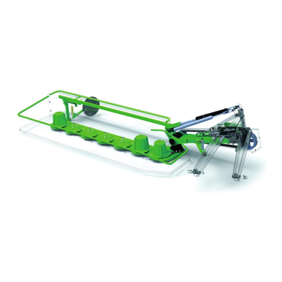
Main frame, on which the cutterbar (4) is situated, is supported by the springs (7). Swath guides (5) are mounted on the main frame. Fig. 3b. Parts of SaMASZ rear disc mower with tine conditioner 1 – 3-point linkage frame 6 –... -
Page 8: Standard Equipment And Spare Parts
Main frame, on which the cutterbar is situated, is supported by the springs (7). Swath guides (5) are mounted on the main frame. Fig. 3c. Parts of SaMASZ rear disc mower with tine conditioner 1 – 3-point linakge frame 6 –... - Page 9 Lubricate the PTO shaft with high quality multi-purpose grease every 50 shaft operating hours. If access holes are available, lubricate fittings through access holes. PTO shafts of other brands with equivalent parameters could be used afer first obtaining SaMASZ permission.
-
Page 10: Safety Precations
Rear disc mowers Operator’s manual 4. SAFETY PRECATIONS The following precautions are for your safety. They must be read carefully and followed by every person who operates or maintains the machine. Failure to follow these safety precautions could result in serious injury or death to the operator, maintenance person or bystanders and property damage to the machine and surrounding property. - Page 11 In the event of an accident involving this mower in a field or on a road, follow all applicable first aid procedures and contact SaMASZ technical service. Mower should be kept clean, so as to avoid danger of fire.
-
Page 12: Conditions Of Mounting Mower On Tractor
Rear disc mowers Operator’s manual 4.2. Conditions of mounting mower on tractor Prior to the mounting operation, be sure that the tractor and mower hitches are compatible and that the tractor's hitch load is adequate for the machine which is to be mounted or attached. Prior to mounting the machine, examine the technical condition of the mower's hitch assembly and tractor's 3-point linkage. -
Page 13: Putting The Mower Onto Another Vehicle For Transport
Rear disc mowers Operator’s manual 4.3.1. Putting the mower onto another vehicle for transport The driver and the carrier are responsible for the mower’s transport safety. Equipment and parts must be secured during transport. To put the mower onto another vehicle in a safe way, please obey the following rules: Transport should be done by qualified and specifically trained personnel, Grab the mower by any lifting devices only in places indicated by hook sign (Fig. -
Page 14: Working Parts
Rear disc mowers Operator’s manual Fig. 6. Location of centre of gravity on mowers KDT Tab. 4. Location of centre of gravity Model Dimension [ft in] KDT 180 KDT 220 KDT 260 KDT 300 KDT 340 KDT 341 2′ 5″... -
Page 15: Residual Risk
4.7. Residual risk Despite the fact that SaMASZ, the manufacturer of the mower, has taken great care in the design and manufacturing of the mower, certain risks during mower operation and maintenance are unavoidable. A major source of risk that could result in serious injury or death can occur during the performance of these operations. -
Page 16: Residual Risk Assessment
Rear disc mowers Operator’s manual 4.7.5. Residual risk assessment Residual risk occurs from not complying with the instructions and safety precautions. Such risk can be minimized by doing the following: thorough familiarizing yourself with operator’s manual, allow no persons on the machine when operating, allow no persons within the mower operation range, adjust, maintain and lubricate the machine with the engine off, only skilled persons should perform repairs of the machine,... - Page 17 Rear disc mowers Operator’s manual N-11 N-14 N-15 Lubrication point N-16 N-23 N-29 Watch out: power lines N-32 N-40 Transport hook for lifting of the mower N-48 N-49 N-50 N-55 Stay a way from mower’s Never stand near tractor’s Do not stay in the swinging inclination area 3-point linkage while area of mower’s parts...
- Page 18 Rear disc mowers Operator’s manual N-168 N-187 N-204 N-205 Do not touch the machine Use the required Personal Use the required Personal Cutterbar "Perfect Cut" before the rotating parts Protective Protective have not come to a complete standstill N-206 N-213 N-224 Use the required Personal (for KDT S/SL)
-
Page 19: Operation
Rear disc mowers Operator’s manual N-40 N-29 N-40 N-109 N-01 ; N-02 ; N-03 ; N-04 N-06 ; N-07 ; N-23 ; N-48 N-49 ; N-50 ; N-117 N-09 N-167 ; N-168 ; N-204 N-213 N-205 ; N-206 ; N-224 N-14;... -
Page 20: Preparing The Mower For Transport
Rear disc mowers Operator’s manual After the mower has been attached to tractor, check the balance and steerability of tractor-mower set. To do this, calculate to formulas given in the appendix or weigh the set, and then drive on the scales only with front axis of the tractor (the mower must be in transport position –... -
Page 21: Preparing The Mower For Transport On Public Roads
Rear disc mowers Operator’s manual Fig. 10. Shut-off valve position: a) open(work), b) closed(transport) Fig. 11. Rear disc mower in its transport position 5.3. Preparing the mower for transport on public roads WARNING: Legal requirements for transport on public roads may differ from state to state. -
Page 22: Moving From Transport To Working Position
Rear disc mowers Operator’s manual Fig. 12. Instruction of PTO shaft shortening CAUTION: Handle all parts with utmost care. Never place your hands or fingers between one part and the other. Wear safety clothes such as gloves, protective footwear and goggles. The operation of shortening must be carried out with the utmost care as the PTO shaft will have to be replaced if the telescopic shafts are shortened to an excessive extent. -
Page 23: Operating Positions Of The Mower
The proper distance between the end of cutterbar and tractor’s tyre Y should be about 0 to 4″ for KDT 180, KDT 220, KDT 260. For KDT 300 Y should be between 11.8″ and 1′ 4. For KDT 340, KDT 341 between 1′ 8″ and 1′ 12″. -
Page 24: Preparing The Mower For Work
5.6. Preparing the mower for work NOTICE: Before sale SaMASZ protects the cylinders with special grease against weather which may cause premature wear. Before operating the mower, remove the exceess grease from the cylinders. Put the mower into motion when the cutterbar is on the ground so that oil can fill the whole cutterbar. -
Page 25: Essential Information Concerning Mowing
Rear disc mowers Operator’s manual 2. There is however a certain disadvantage - creased stubble, especially when it comes to lying grass. Straight grass may be mowed with horizontal adjustment of the mower and then the stubble will be even, but it will not look as attractive as with 2-drum or 4-drum mowers, because the knives work horizontally to the ground and inclined grass bends because of wind blasts. -
Page 26: Design And And Operation Of Safety Breakaway Device
Rear disc mowers Operator’s manual Fig. 15. Shape of the stubble with cutterbar’s inclination 0°, 3° and 5° 5.7.2. Design and and operation of safety breakaway device In the event of hitting an immovable obstacle one of the safety device flat bars slides out and disconnects the safety device. -
Page 27: Mower Clogging
Rear disc mowers Operator’s manual Recommended length of safety device spring R (Fig. 16) should be 5.6". If the safety device breaks away too easily, tighten up the spring approximately .04"-.08". DO NOT tighten up too much, because you may prevent the safety device from working and damage the mower. 5.7.3. -
Page 28: Mounting And Adjustments
Rear disc mowers Operator’s manual 6. MOUNTING AND ADJUSTMENTS 6.1. Mounting and timing of the knives The knives should be mounted as shown in 19 and Fig. 20. The knives recommended by the Fig. manufacturer recommended knives are measured 105x49x4 and conform to standard PN-EN 795:2002. -
Page 29: Adjusting The Cutterbar
Swath width is adjusted with swath guides mounted on the 3-point linkage frame of the cutterbar (Fig. 21). In order to adjust the guide, the following should be performed (for: KDT 180, KDT 220, KDT 260, KDT 300, KDT 340):... - Page 30 Rear disc mowers Operator’s manual Fig. 22. Adjustment of swath guides: 1- swath guide, 2 - adjustment screw, 3 - swath wheel In order to set swath width, adjustment of swath guides (1) should be performed (Fig. 23) (for: KDT 220 W, KDT 260 W): loosen eye screw (2) of the swath guide, set the swath guide (1) as needed, tighten screw (2).
-
Page 31: Adjusting The Cutting Height
NOTICE: Due to high discs rpm speed, change knife holders in sets of the same weight – each holder has weight marked. Improperly changed knife holders will damage disc bearings. KDT 180 KDT 220 KDT 260 KDT 300 KDT 340... -
Page 32: 3-Point Linkage Support Chain
Rear disc mowers Operator’s manual 6.5. 3-point linkage support chain " Fig. 26. Support chain Support chain is used to ensure 3-point linkage frame of the mower is always at the same height, to set the mowing unit parallel to the ground and to relieve the hydraulic lift of the tractor. When connecting mower to the tractor, the hanger plate A of support chain should be disconnected from chain and put on the pin B of upper link (Fig. -
Page 33: Replacing The Conditioner's Tines
Rear disc mowers Operator’s manual 6.7. Replacing the conditioner’s tines (Models: KDT 220 S and KDT 260 S(SL)) Prior to commencing any operation, check condition of bolts on which flails are set, as well as condition of fails themselves. If flails or bolts are worn or damaed, it is necessary to replace them. Bear in mind, that flails should be replaced in pairs (opposite) featuring the same weight in order to keep shaft well balanced. -
Page 34: Adjusting Force Of The Prssure Of Roller Conditioner
Rear disc mowers Operator’s manual Tab. 5. Torque values for bolts In the absence of specific torque values, the following chart can be used as a guide to the maximum safe torque for a particular size and grade of fastener. There is no torque difference for fine or coarse threads. -
Page 35: Checking The Tension Of The V-Belts
Rear disc mowers Operator’s manual min. Fig. 30. Permissible wear of knife holder pin on disk a) knife base M12 b) knife base M12 with claw NOTICE: If the knife is missing or disc cover plate is damaged the vibrations may occur, which leads to cutterbar’s damage. -
Page 36: Daily Maintenance
Rear disc mowers Operator’s manual Fig. 32a. Rollers transmission guard Fig. 32b. Adjusting tension of transmission toothed belt Fig. 32c. Conditioner roller transmission Fig. 32d. Adjusting tension of toothed belt for guard conditioner roller transmission 6.9.4. Daily maintenance When you finish each day of operation carry out the following maintenance: check all visible parts and components and their connections;... -
Page 37: Lubrication
0.3" from the cutterbar bottom. Oil capacities are given in table below. Tab. 6. Oil capacities Model Oil capacity [l] Oil type Lubrication frequency KDT 180 – 5' 11" KDT 220 S/W – 7' 3" KDT 260 S,SL/W – 8' 6" Once every 3 seasons 80W90 (if working intensively more frequently) KDT 300 –... -
Page 38: Intersecting Axis Gear
Rear disc mowers Operator’s manual 7.2. Intersecting axis gear Everyday before starting work please check the oil level and, if needed, please refill after having removed the vent A on the top of the gear (Fig. 34). The oil level can be checked through the check opening B on the side of the gear. -
Page 39: Bearings And Joints
Rear disc mowers Operator’s manual Lubrication point Lubrication points Fig. 37. Bearing lubrication point Fig. 38. Bearing lubrication point with LT43 grease with LT43 grease 7.4. Bearings and joints Every 50 mower working hours lubricate tine/roller conditioner’s bearings (Fig. 36, Fig. 37, Fig. -
Page 40: Malfunction And Their Repairs
Damaged gears in the cutterbar. This repair must be done by Mower is blocked Damaged bearings in the disc hub SaMASZ service Damaged or dirty hydraulic cylinder Replace or clean hydraulic Mower’s hydraulics does not and check valve... -
Page 41: Disassembly And Withdrawal From Use
2. The warranty period is for two years from the date of sale to the purchaser, stated above. 3. Any repair which is subject to warranty should be carried out by an authorised SaMASZ dealer. Upon completion of the repair the dealer must submit a warranty claim within 14 days. -
Page 42: Warranty Repairs Record
SaMASZ, e) negligent maintenance, use of non-genuine spare or replacement parts that are not specifically designed for... -
Page 43: Appendix Calculating Axis Load
Rear disc mowers Operator’s manual APPENDIX CALCULATING AXIS LOAD ATTENTION! When mounting the machine on a tractor using front and/or rear 3-point linkage, a maximum value of permissible load cannot be exceeded – tractor's front axis load must be 20% of the tractor's overall weight. Before using the tractor-machine assembly, check whether these conditions are met, while calculating and weighing the assembly. - Page 44 Rear disc mowers Operator’s manual Calculating minimum weight of front ballast M – machine mounted at tractor's rear or P min. at rear and front: Calculating minimum weight of rear ballast M – machine mounted at tractor's front: T min. Calculating real axis load at tractor's front axis T P rzecz .
Need help?
Do you have a question about the KDT 180 and is the answer not in the manual?
Questions and answers