Table of Contents
Advertisement
Quick Links
OPERATION MANUAL
REAR DISC MOWER WITH
CENTRAL SUSPENSION
Standard
KT 261 (H)
- 2,6 m
KT 301 (H)
- 3,0 m
KT 341 (H)
- 3,4 m
KT 261 S (H) - 2,6 m
KT 301 S (H) - 3,0 m
KT 260 W (H) - 2,6 m
KT 300 W (H) - 3,0 m
Wide
swath
Wide
conditioner
Swath
rollers
Serial No:
SaMASZ Sp. z o.o.
Poland, 15-161 Białystok, ul. Trawiasta 15
Established – 1984
On special order
KT 260 (H)
- 2,6 m
KT 300 (H)
- 3,0 m
KT 340 (H)
- 3,4 m
KT 260 S (H) - 2,6 m
KT 300 S (H) - 3,0 m
NIP 966-159-29-76
tel. (+48) (85) 654 45 84
Fax (+48) (85) 664 70 41
E-mail: samasz@samasz.pl
www.samasz.pl
Narrow
swath
Narrow
conditioner
IN541EN003
20.03.20112
VERSION NO 3
Advertisement
Table of Contents

Related Manuals for SaMASZ KT 261


Summary of Contents for SaMASZ KT 261
- Page 1 - 3,0 m swath swath KT 341 (H) - 3,4 m KT 340 (H) - 3,4 m KT 261 S (H) - 2,6 m KT 260 S (H) - 2,6 m Wide Narrow conditioner conditioner KT 301 S (H) - 3,0 m...
- Page 2 Tilting the mower in the direction of travel by app. 0°-5° is recommended. Mowing in the vertical position is allowed. Tilting the mower in the opposite direction will result in permanent damage to the cutter bar. IT IS FORBIDDEN TO TURN ON THE MOWER BEFORE THE MOWER IS IN WORKING POSITION IT IS FORBIDDEN...
-
Page 3: Table Of Contents
Rear disc mowers with central suspension Operating manual - with hydro-pneumatic or spring suspension Table of contents page DEVICE IDENTIFICATION ......................... 2 INTRODUCTION ............................ 2 INTENDED USE ............................3 3.1. Technical data ............................4 3.2. Construction and operation ........................8 3.3. -
Page 4: Device Identification
Rear disc mowers with central suspension Operating manual - with hydro-pneumatic or spring suspension 1. DEVICE IDENTIFICATION The mower identification plate is affixed permanently to the body of the mower shown on Fig. 1. Fig. 1. Location of the identification plate Fig. -
Page 5: Intended Use
Rear disc mowers with central suspension Operating manual - with hydro-pneumatic or spring suspension 3. INTENDED USE 1. A mower without crop scarifier or rollers is equipped with the „Perfect Cut” cutterbar or optionally with the „Heavy Duty” cutterbar. In table 1 the mowing height differences, depending on the tilt angle of the cutterbar are shown. -
Page 6: Technical Data
Line cutting speed 86.2 m/s Disc rotational speed 3078 rpm Tab. 2b. Technical data – Rear disk mower with hydro-pneumatic support (wide swath) Standard KT 261 H KT 301 H KT 341 H Mower type: Wide swath Mower type: 2.60 m 3.00 m... - Page 7 Rear disc mowers with central suspension Operating manual - with hydro-pneumatic or spring suspension Tab. 3a. Technical data – Rear disk mower with support springs (narrow swath) On special order KT 260 KT 300 KT 340 Mower type: Narrow swath Mower type: 2.60 m 3.00 m...
- Page 8 5 t Tab. 4b. Technical data – Rear disk mower with hydro-pneumatic support (with conditioner) Standard On special order KT 261 S H KT 301 S H KT 260 S H KT 300 S H...
- Page 9 Rear disc mowers with central suspension Operating manual - with hydro-pneumatic or spring suspension Tab. 5a. Technical data – Rear disk mower with support springs (with swath rollers) Standard KT 260 W KT 300 W Mower type: Swath rollers Mower type: 2.60 m 3.00 m Mowing width...
-
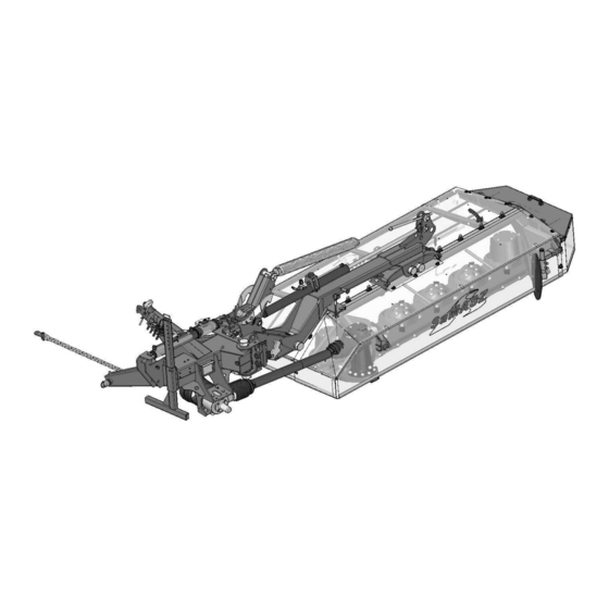
Page 10: Construction And Operation
- with hydro-pneumatic or spring suspension 3.2. Construction and operation 10 11 Fig. 3a. Overview of rear disk mower (wide swath) (For: KT 261, KT 301, KT 341 1 – Suspension frame 7 – PTO I 2 – Lifting actuator 8 –... - Page 11 Rear disc mowers with central suspension Operating manual - with hydro-pneumatic or spring suspension 10 11 Fig. 3b. Overview of rear disk mower (narrow swath) (On special order, for: KT 260, KT 300, KT 340) 1 – Suspension frame 7 – PTO I 2 –...
- Page 12 Operating manual - with hydro-pneumatic or spring suspension 4 13 Fig. 3c. Overview of rear disk mower (wide conditioner) (For: KT 261 S, KT 301 S) 1 – Suspension frame 8 – Miter gear I 2 – Lifting actuator 9 – Miter gear II 3 –...
- Page 13 Rear disc mowers with central suspension Operating manual - with hydro-pneumatic or spring suspension 5 12 Fig. 3d. Overview of rear disk mower (narrow conditioner) (On special order, for: KT 260 S, KT 300 S, KT 340 S) 1 – Suspension frame 8 –...
- Page 14 Rear disc mowers with central suspension Operating manual - with hydro-pneumatic or spring suspension Fig. 3e. Overview of rear disk mower (swath rollers) (For: KT 260 W, KT 300 W) 1 – Suspension frame 8 – Miter gear II 2 – Lifting actuator 9 –...
- Page 15 Rear disc mowers with central suspension Operating manual - with hydro-pneumatic or spring suspension All KT disk mowers are also offered with hydro-pneumatic support. Fig. 3f. Overview of rear disk mower with hydro-pneumatic support (For all KT disk mowers) Hydraulic lifting cylinder (1) and hydro-pneumatic suspension fed from the tractor external hydraulics and hydraulic accumulators (3) are used to adjust the mower to working position.
-
Page 16: Equipment And Spare Parts
KT 210 and KT 261 H – 1 pack, KT 301 – 341 and KT 301 H – 341 H – 2 packs, KT 260 and KT 260 H – 1 pack, KT 300 – 340 and KT 300 H – 340 H – 2 packs, a special wrench for blade replacement, an articulated telescopic shaft with unidirectional clutch. -
Page 17: Safety Rules And Warnings
Rear disc mowers with central suspension Operating manual - with hydro-pneumatic or spring suspension 4. SAFETY RULES AND WARNINGS 4.1. General rules During operation of the mower the Regulation of the Farm Ministry and Food Economy (Rozporządzenie Ministra Rolnictwa i Gospodarki Żywnościowej) from 12-01-1998 dealing with safety and hygiene during the operation of tractors, machinery, tools and equipment used for farming (Dz. - Page 18 Rear disc mowers with central suspension Operating manual - with hydro-pneumatic or spring suspension The regulator line changing the position of the mower should have enough slack and be properly installed in the cabin of the tractor. The tractor used with the mower should be equipped with a driver's cabin. The mower cannot be used if the tractor has not been properly balanced.
-
Page 19: Transport
Rear disc mowers with central suspension Operating manual - with hydro-pneumatic or spring suspension 4.2. Transport Any changes in the position of the mower can only be done after making sure that there are no people in the vicinity of the mower (be careful of children). During time of transport install on the mower the portable light board and the triangular safety sign identifying a slow moving vehicle. -
Page 20: Residual Risk
- with hydro-pneumatic or spring suspension 4.5. Residual risk Despite the fact, that SaMASZ Sp. z o. o. Białystok company – the manufacturer of the mower takes the responsibility for the mower design and manufacturing, in order to eliminate hazard, certain risk when operating the mower is unavoidable. -
Page 21: Residual Risk Assessment
Rear disc mowers with central suspension Operating manual - with hydro-pneumatic or spring suspension WARNING: If the instructions and prohibitions are not adhered to there remains residual risk. 4.5.1. Residual risk assessment When keeping such recommendations as: thorough familiarizing with operator’s manual, no persons remaining on the machine when operating and during drives, no persons remaining within the mower operation range, adjustment, maintenance and lubrication of the machine with engine off,... - Page 22 Rear disc mowers with central suspension Operating manual - with hydro-pneumatic or spring suspension 7. N-9 8. N-11 9. N-23 Warning: rotor 10. N-28 11. N-40 12. N-48 Transport hook for lifting of Stay a way from mower’s the mower inclination area 13.
- Page 23 Rear disc mowers with central suspension Operating manual - with hydro-pneumatic or spring suspension N -35 Cutterbar "Perfect Cut" 20. N-31 N-35 Cutterbar "Heavy Duty" 24. N-55 23. N-53 25. N-63 26. N-74 27. N-71 28. N-75 29. N-83 31. P-2 30.
- Page 24 Rear disc mowers with central suspension Operating manual - with hydro-pneumatic or spring suspension Labels for hydraulic hoses: 1. Lifting the mower backwards 2. Unfolding the mower to the side 3. Folding and unfolding of the mower into transport or operating position. Setting pressure on the ground.
- Page 25 Rear disc mowers with central suspension Operating manual - with hydro-pneumatic or spring suspension Fig. 6b. Locations of warning signs (mowers with wide conditioner) Fig. 6c. Locations of warning signs (mowers with swath rollers) - 2 3 -...
-
Page 26: Operation And Construction Of The Hydraulic Safety Device
Rear disc mowers with central suspension Operating manual - with hydro-pneumatic or spring suspension ATTENTION: All assemblies used for repairs should have all necessary warning signs originally used by the manufacturer. 4.7. Operation and construction of the hydraulic safety device The hydraulic safety device protects the cutting elements of the mower from driving onto low obstacles. -
Page 27: Operation Of The Mower
Tractor class Standard Wide conditioner With support springs With hydro-pneumatic support Mower’s type KT 261 S KT 301 S KT 261 S H KT 301 S H Tractor power 80 KM 90 KM 80 KM 90 KM Tractor class On special order... -
Page 28: Connecting The Articulated Telescopic Shaft (Ats)
Rear disc mowers with central suspension Operating manual - with hydro-pneumatic or spring suspension 2. The mower should be connected to the tractor using the three point hitch (TPH), as shown on Fig. 9. The hangers W of the lower ties of the tractor should be placed under the bolts A (Fig. - Page 29 Rear disc mowers with central suspension Operating manual - with hydro-pneumatic or spring suspension Fig. 10. Preparing the mower for operation To prepare the mower for operation: 1. Lift mower onto 3-point linkage frame. Connect hydraulic hoses. 2. Open valve (A) on short cylinder position - I. Lift the machine on tractor’s links and move longer cylinder to the maximum (C), valve (A) should be in pos.
-
Page 30: Gas Pressure In The Accumulator And In The Entire System For Each Mower Model
Gas pressure in the accumulator System pressure (manometer [bar] reading) [bar] KT 261 H KT 260 H KT 261 S H KT 260 S H KT 260 W H KT 301 H KT 300 H KT 301 S H KT 300 S H... -
Page 31: Operating The Mower
Rear disc mowers with central suspension Operating manual - with hydro-pneumatic or spring suspension 5.5. Operating the mower Dear Operator, If this is your first experience with a disc mower (previously you used a 2-drum mower) then you may need some obvious information: 1. -
Page 32: Mower Positioning During Directional Changes
Rear disc mowers with central suspension Operating manual - with hydro-pneumatic or spring suspension With re-cultivated pastures during first mowing or after long lasting heavy rains it is necessary to reduce the pressure of the bar on the ground by adjusting the spring or the hydro-pneumatic suspension. - Page 33 Rear disc mowers with central suspension Operating manual - with hydro-pneumatic or spring suspension Transport lock Fig. 12. Transport lock: a) operating position (mowing), b) transport position with lifted mower with mowers with spring or hydro-pneumatic suspension the proper positions of the locking bar of the tie are shown on Fig.
-
Page 34: Preparing The Mower For Transport On Public Roads
Rear disc mowers with central suspension Operating manual - with hydro-pneumatic or spring suspension 5.7. Preparing the mower for transport on public roads Road safety and current traffic laws demand that during transport the mower be equipped with the following items: portable light board consisting of a panel installed in the socket of the upper guard (not included with the mower). -
Page 35: Changing The Mower Position From Transport To Operating Position
Rear disc mowers with central suspension Operating manual - with hydro-pneumatic or spring suspension ATTENTION: If the purchaser of the mower does not own the safety equipment mentioned above it can be purchased from the mower's manufacturer. WARNING: Do not drive on public roads if the machine's transport height is more than 4 m (for mower KT 340 –... -
Page 36: Assembly And Settings
Y, the distance between the interior cutting disc and the tires of the tractor, is from 0 to 10 cm with KT 260 (H) and KT 261 (H). With KT 300 H and KT 301 (H) the distance Y should be from 30 to 40 cm and with KT 340 (H) and KT 341 (H) from 50 to 60 cm. -
Page 37: Blade Replacement
Swath width is adjusted with swath guides mounted on the 3-point linkage frame of the cutterbar (Fig. 19). In order to adjust the guide, the following should be performed (for: KT 261 (H), KT 301 (H), KT 341 (H), KT 260 (H), KT 300 (H) and KT 340 (H)):... - Page 38 In order to set swath width, adjustment of swath guides (1) should be performed (Fig. 20) (for: KT 261 S (H), KT 301 S (H), KT 260 S (H) and KT 300 S (H)): loosen eye screw (2) of the swath guide,...
- Page 39 (1) as needed, tighten screw (2). Fig. 21. Adjustment of swath guides: 1- swath guide, 2 - adjustment screw KT 261 i KT 261 H (wide swath) KT 260 i KT 260 H (narrow swath) - 3 7 -...
- Page 40 Rear disc mowers with central suspension Operating manual - with hydro-pneumatic or spring suspension KT 301 i KT 301 H (wide swath) KT 300 i KT 300 H (narrow swath) KT 341 i KT 341 H (wide swath) KT 340 i KT 340 H (narrow swath) Disc Disc with out...
-
Page 41: Setting Mowing Height
Rear disc mowers with central suspension Operating manual - with hydro-pneumatic or spring suspension ATTENTION: Since the mowing width is different in the mowers manufactured by us (and different directions of disc rotation) the disc rotation direction should be verified before blade installation (Fig. 22). WARNING: Due to the high revolutions of the discs, blade holders should be replaced in pairs of the same weight - every holder has its weight stamped on it. -
Page 42: Adjustment Of The Gap Between The Cover And The Roller Of The Scarifier
6.6. Adjustment of the gap between the cover and the roller of the scarifier (For mowers: KT 260 S (H), KT 300 S (H) and KT 261 S (H), KT 301 S (H)) Depending on the height and thickness of the grass being mowed, it may become necessary to change the setting of the scarifier cover. -
Page 43: Adjustment Of The Pressure Between The Rollers
Rear disc mowers with central suspension Operating manual - with hydro-pneumatic or spring suspension 1. Self locking nut M16 oc. kl. 8 2. Flat washer ∅16 3. Set screw 10x8x40 4. Bolt M16x70 kl. 10.9 5. Steel flail 6. Scarifier shaft Fig. -
Page 44: Checking The Tautness Of The Chain Of The Chain Drive Of The Scarifier And Rollers
Rear disc mowers with central suspension Operating manual - with hydro-pneumatic or spring suspension WARNING: The loss of a blade can cause vibrations which can lead to damage of the cutterbar. In such cases warranty claims will be rejected. In the event of blade damage the whole set (2 pcs) should be immediately replaced. -
Page 45: End Of Season Maintenance
Tab. 8. Amount of oil necessary for different cutterbars Mower type Amount of oil [l] Oil type Frequency of oil changes KT 261 S (H) KT 260 S/W (H) – 2.60 m KT 261 S (H) once every 3 seasons 80W90 KT 300 S/W (H) –... -
Page 46: Miter Gears
Rear disc mowers with central suspension Operating manual - with hydro-pneumatic or spring suspension Fig. 31. Control and oil changing points of the cutterbar 7.2. Miter gears Every day before operation the oil level should be checked and if necessary topped off after removing the plug A (Fig. -
Page 47: Roller Gear
Rear disc mowers with central suspension Operating manual - with hydro-pneumatic or spring suspension 7.3. Roller gear Prior to checking the oil level in the gear box of the roller the safety cover must be removed. The oil level should be checked in the roller gear box and if necessary it should be topped off after removing plug (deaerator) A (Fig. -
Page 48: Chain Drives Of The Roller And The Scarifier
Rear disc mowers with central suspension Operating manual - with hydro-pneumatic or spring suspension 7.4. Chain drives of the roller and the scarifier 1. On Fig. 37 are shown openings through which the chains of the chain drives can be lubricated. These points are additionally designated by N-75 labels. -
Page 49: Malfunctions And Their Correction
Rear disc mowers with central suspension Operating manual - with hydro-pneumatic or spring suspension 8. MALFUNCTIONS AND THEIR CORRECTION Malfunction Cause Recomendation Some missing blades Install or replace blades Worn blades Replace worn blades Improperly installed blades Install blades according to (left –... -
Page 50: Mower Repair And Disposal
Rear disc mowers with central suspension Operating manual - with hydro-pneumatic or spring suspension 9. MOWER REPAIR AND DISPOSAL 9.1. Repair Before repairing or assessing weather the mower is still serviceable, the machine should be carefully cleaned of dirt, mud and plant remains. After checking nuts and bolts, proper slack in joints, gears we can assess weather the machine is still serviceable. -
Page 51: Warranty Conditions
Rear disc mowers with central suspension Operating manual - with hydro-pneumatic or spring suspension 11. WARRANTY CONDITIONS 11.1. Warranty claims procedures 1. The manufacturer guarantees the quality and proper function of the mower covered by this warranty. 2. Faults or malfunctions of the mower which become apparent within a 24 month period of the date of purchase will be corrected free of charge at the buyer's residence. -
Page 52: Record Of Warranty Repairs
Providing this information is the responsibility of the distributor. ATTENTION: The SaMASZ Company is continually working on improvement and development of all types and models of mowers. For this reason the form, accessories and technology of delivered products can change. No claims can be made based on the data, illustrations or descriptions contained in this manual or the spare parts catalogue.