Table of Contents
Advertisement
Quick Links
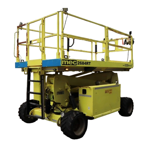
84RT Series
Speed Level™
Serial Number
11800001 - up
91857rev2
February 2013
Operator's Manual
Introduction . . . . . . . . . . . . . . . . . . . . . . . . . . . . . . . . . . . . . . . . . . . . . . . . . . . . 1
Safety . . . . . . . . . . . . . . . . . . . . . . . . . . . . . . . . . . . . . . . . . . . . . . . . . . . . . . . . . . 2
Safety Alert Symbols . . . . . . . . . . . . . . . . . . . . . . . . . . . . . . . . . . . . . . . . . . . . . . . 3
Fall Protection . . . . . . . . . . . . . . . . . . . . . . . . . . . . . . . . . . . . . . . . . . . . . . . . . . . . . 3
Electrocution Hazard . . . . . . . . . . . . . . . . . . . . . . . . . . . . . . . . . . . . . . . . . . . . . . 4
Tip-over Hazards . . . . . . . . . . . . . . . . . . . . . . . . . . . . . . . . . . . . . . . . . . . . . . . . . . 5
Fall Hazards . . . . . . . . . . . . . . . . . . . . . . . . . . . . . . . . . . . . . . . . . . . . . . . . . . . . . . . 6
Collision Hazards . . . . . . . . . . . . . . . . . . . . . . . . . . . . . . . . . . . . . . . . . . . . . . . . . . 6
Additional Safety Hazards. . . . . . . . . . . . . . . . . . . . . . . . . . . . . . . . . . . . . . . . . . 7
Battery Safety . . . . . . . . . . . . . . . . . . . . . . . . . . . . . . . . . . . . . . . . . . . . . . . . . . . . . 7
Jobsite Inspection . . . . . . . . . . . . . . . . . . . . . . . . . . . . . . . . . . . . . . . . . . . . . . . 8
Functions Test . . . . . . . . . . . . . . . . . . . . . . . . . . . . . . . . . . . . . . . . . . . . . . . . . . 8
Operating Instructions. . . . . . . . . . . . . . . . . . . . . . . . . . . . . . . . . . . . . . . . . . . 9
Prestart . . . . . . . . . . . . . . . . . . . . . . . . . . . . . . . . . . . . . . . . . . . . . . . . . . . . . . . . . . . 9
Starting Engine from Lower Control Panel . . . . . . . . . . . . . . . . . . . . . . . . . 10
Starting Engine from Upper Control Box. . . . . . . . . . . . . . . . . . . . . . . . . . . 11
Base Controls Operation and Test . . . . . . . . . . . . . . . . . . . . . . . . . . . . . . . . . 12
Platform Control Operation and Test . . . . . . . . . . . . . . . . . . . . . . . . . . . . . . 13
Joystick Operation . . . . . . . . . . . . . . . . . . . . . . . . . . . . . . . . . . . . . . . . . . . . . . . . 14
Leveling Procedure . . . . . . . . . . . . . . . . . . . . . . . . . . . . . . . . . . . . . . . . . . . . . . . 16
Shutdown Procedure . . . . . . . . . . . . . . . . . . . . . . . . . . . . . . . . . . . . . . . . . . . . . 16
Deck Extension -- 2684 models only . . . . . . . . . . . . . . . . . . . . . . . . . . . . . . . 17
Emergency Systems . . . . . . . . . . . . . . . . . . . . . . . . . . . . . . . . . . . . . . . . . . . . 18
Emergency Stop . . . . . . . . . . . . . . . . . . . . . . . . . . . . . . . . . . . . . . . . . . . . . . . . . . 18
Emergency Lowering . . . . . . . . . . . . . . . . . . . . . . . . . . . . . . . . . . . . . . . . . . . . . 18
Fold Down Platform Railings . . . . . . . . . . . . . . . . . . . . . . . . . . . . . . . . . . . . 20
Machine Inspections . . . . . . . . . . . . . . . . . . . . . . . . . . . . . . . . . . . . . . . . . . . . 22
Annual Inspection Report . . . . . . . . . . . . . . . . . . . . . . . . . . . . . . . . . . . . . . . . . 26
Maintenance . . . . . . . . . . . . . . . . . . . . . . . . . . . . . . . . . . . . . . . . . . . . . . . . . . . 27
Routine Maintenance . . . . . . . . . . . . . . . . . . . . . . . . . . . . . . . . . . . . . . . . . . . . . 28
Scheduled Maintenance . . . . . . . . . . . . . . . . . . . . . . . . . . . . . . . . . . . . . . . . . . 28
Maintenance Safety. . . . . . . . . . . . . . . . . . . . . . . . . . . . . . . . . . . . . . . . . . . . . . . 28
Lubrication . . . . . . . . . . . . . . . . . . . . . . . . . . . . . . . . . . . . . . . . . . . . . . . . . . . . . . . 29
Component Locations . . . . . . . . . . . . . . . . . . . . . . . . . . . . . . . . . . . . . . . . . . 30
Full Machine. . . . . . . . . . . . . . . . . . . . . . . . . . . . . . . . . . . . . . . . . . . . . . . . . . . . . . 30
Modules. . . . . . . . . . . . . . . . . . . . . . . . . . . . . . . . . . . . . . . . . . . . . . . . . . . . . . . . . . 31
Upper Controls . . . . . . . . . . . . . . . . . . . . . . . . . . . . . . . . . . . . . . . . . . . . . . . . . . . 32
Lower Controls . . . . . . . . . . . . . . . . . . . . . . . . . . . . . . . . . . . . . . . . . . . . . . . . . . . 33
Decals . . . . . . . . . . . . . . . . . . . . . . . . . . . . . . . . . . . . . . . . . . . . . . . . . . . . . . . . . 34
Troubleshooting . . . . . . . . . . . . . . . . . . . . . . . . . . . . . . . . . . . . . . . . . . . . . . . 36
Serial Plate Location . . . . . . . . . . . . . . . . . . . . . . . . . . . . . . . . . . . . . . . . . . . . . . 37
Serial Plate Description . . . . . . . . . . . . . . . . . . . . . . . . . . . . . . . . . . . . . . . . . . . 37
Transport and Lifting Instructions. . . . . . . . . . . . . . . . . . . . . . . . . . . . . . . 38
Loading . . . . . . . . . . . . . . . . . . . . . . . . . . . . . . . . . . . . . . . . . . . . . . . . . . . . . . . . . . 38
Disengage Brakes before Towing or Winching . . . . . . . . . . . . . . . . . . . . . 38
Engage Brakes before Driving . . . . . . . . . . . . . . . . . . . . . . . . . . . . . . . . . . . . . 38
Lifting and Tie Down Instructions . . . . . . . . . . . . . . . . . . . . . . . . . . . . . . . . . 40
Advertisement
Table of Contents

Related Manuals for Mec Speed Level 84RT Series


Summary of Contents for Mec Speed Level 84RT Series
-
Page 1: Table Of Contents
Operator’s Manual Introduction ........... . 1 Safety . - Page 2 Manual and self-leveling, side/side to 14°, fore/aft to 10° Brakes Dual Rear Wheel Multi-disc Meets requirements of ANSI 92.6:2006 and CSA B354.4. Speed Level™ is a trademark of MEC. *Working Height adds 6 feet (2 m) to platform height. **Weight may increase with certain options or country standards.
-
Page 3: Introduction
This Operator’s Manual has been designed to provide you, the customer, with the instructions and operating procedures essential to properly and safely operate your MEC Aerial Work Platform for its intended purpose of positioning personnel, along with their necessary tools and materials, to overhead work locations. -
Page 4: Safety
MEC designs aerial work platforms to be safe and reliable. They are intended to position personnel, along with their necessary tools and materials, to overhead work locations. The owner/user/operator of the machine should not accept responsibility for the operation of the machine unless properly trained. -
Page 5: Safety Alert Symbols
84RT Series Speed Level™ Safety Safety Alert Symbols MEC manuals and decals use symbols and colors to help you recognize important safety, operation and maintenance information. RED – Indicates an imminently hazardous situation which, if not avoided, will result in death or serious injury. -
Page 6: Electrocution Hazard
84RT Series Speed Level™ Safety Electrocution Hazard ELECTROCUTION HAZARD!!! THIS MACHINE IS NOT INSULATED! DEATH OR SERIOUS INJURY will result from contact with or inadequate clearance from any electrically charged conductor. You must maintain a CLEARANCE OF AT LEAST 10 FEET (3.05 m) between any part of the machine, or its load, and any electrical line or apparatus carrying over 300 Volts up to 50,000 Volts. -
Page 7: Tip-Over Hazards
DO NOT replace items critical to machine stability with items of different weight or specification. ART_3069 DO NOT modify or alter the work platform without written permission from MEC, as DO NOT PUSH OR PULL modifications can increase weight and/or surface area resulting in instability. -
Page 8: Fall Hazards
84RT Series Speed Level™ Safety Fall Hazards DO NOT sit, stand or climb on the platform guard rails. Maintain a firm footing on the platform floor at all times. DO NOT exit the platform when elevated DO NOT climb down from the platform when elevated. Keep the platform floor clear of debris. -
Page 9: Additional Safety Hazards
84RT Series Speed Level™ Safety Additional Safety Hazards Explosion and Fire Hazards DO NOT operate the machine in hazardous locations or locations where potentially flammable or explosive gasses or particles may be present. Damaged Machine Hazards Conduct a thorough pre-start inspection of the machine and test all functions before each work shift to check for damage, malfunction and unauthorized modification. -
Page 10: Jobsite Inspection
84RT Series Speed Level™ Jobsite Inspection Jobsite Inspection DO NOT operate this machine until you have read and understood the Safety section of this manual, have performed the Pre-Start Inspection, Routine Maintenance, and Functions Test, have inspected the jobsite for hazards, and have learned the operating procedures for this machine. -
Page 11: Operating Instructions
84RT Series Speed Level™ Operating Instructions Operating Instructions DO NOT operate this machine until you have read and understood the Safety section of this manual, have performed the Pre-Start Inspection, Routine Maintenance, and Functions Test, have inspected the jobsite for hazards, and have learned the operating procedures for this machine. -
Page 12: Starting Engine From Lower Control Panel
84RT Series Speed Level™ Operating Instructions Starting Engine from Lower Control Panel Be sure that the upper and lower EMERGENCY STOP Switches are reset. • Upper Control Box: Turn Engine Start Switch to RUN. ART_2404 R1 • Lower Control Box: Turn key switch to BASE. ART_3236 Dual Fuel Engine Fuel selection can be made before starting the engine or while engine is running. -
Page 13: Starting Engine From Upper Control Box
84RT Series Speed Level™ Operating Instructions Starting Engine from Upper Control Box • Lower Control Box: Turn the Key Switch to PLATFORM. ART_3234 Dual Fuel Engine • Lower Control Box: Turn the Fuel Selector Switch to the desired fuel, GASOLINE or PROPANE. -
Page 14: Base Controls Operation And Test
84RT Series Speed Level™ Operating Instructions Base Controls Operation and Test IMPORTANT—Be sure the area above the machine is clear of obstructions to allow full elevation of platform. Select BASE Operation • Turn the selector switch to BASE. ART_3236 Emergency Stop •... -
Page 15: Platform Control Operation And Test
84RT Series Speed Level™ Operating Instructions Platform Control Operation and Test IMPORTANT—Check that the route of travel to be taken is clear of persons, obstructions, debris, holes, and drop offs, and is capable of supporting the machine. Select PLATFORM Operation •... -
Page 16: Joystick Operation
84RT Series Speed Level™ Operating Instructions Joystick Operation • Function speed is proportional and is controlled by the movement of the joystick. Steer Proportional • The further it is moved forward, the faster the speed will be. Joystick • The joystick returns to the neutral (center) position when released. F o r w a R e v e r Do not elevate platform unless guardrails are installed and secure... - Page 17 84RT Series Speed Level™ Operating Instructions Drive Torque (Speed Control) Drive speed is selectable until the platform is elevated above 10 Feet (3 m). When the platform is elevated the machine defaults to MID RANGE and the switch is locked-out (non functioning).
-
Page 18: Leveling Procedure
84RT Series Speed Level™ Operating Instructions Leveling Procedure Leveling of the machine can only be performed when the platform height is below the Stowed Height Limit Switch setting of approximately 10 feet (3 m). If the TILT light is ON, the platform must be brought to level or the LIFT function will not operate. -
Page 19: Deck Extension -- 2684 Models Only
84RT Series Speed Level™ Operating Instructions Deck Extension -- 2684 models only The deck will extend in intervals of 8 inches (20 cm) throughout the entire 48 inch (1.2m) length of the deck extension. The extension handle hangs from the top rail at the left side of the deck extension. -
Page 20: Emergency Systems
84RT Series Speed Level™ Emergency Systems Emergency Systems If the control system fails while the platform is elevated, have an experienced operator use the emergency lowering procedure to safely lower the platform. Do not attempt to climb down elevating assembly. Emergency Stop The machine is equipped with an EMERGENCY STOP switch on both control panels. - Page 21 84RT Series Speed Level™ Emergency Systems Upper Controls Emergency Stop Switch 9 1 8 Lower Controls Emergency Stop Switch Emergency Lowering Switch ART_4294 91857rev2– February 2013 Page 19...
-
Page 22: Fold Down Platform Railings
84RT Series Speed Level™ Fold Down Platform Railings Fold Down Platform Railings 3084 Models Open & Secure the Loading Gate • Remove the 2 snap pins that hold the loading gate to the side guardrail. • Swing the loading gate open •... - Page 23 84RT Series Speed Level™ Fold Down Platform Railings Fold Down Rails (continued) 2684 Models Open & Secure The Material Loading Gate • Lift the upper Control Box off the Deck Extension Rail and place out of the way. • Lift the gate latch and swing the Material Loading Gate open.
-
Page 24: Machine Inspections
84RT Series Speed Level™ Machine Inspections Machine Inspections DO NOT operate this machine until you have read and understood the Safety section of this manual, have performed the Pre-Start Inspection, Routine Maintenance, and Functions Test, have inspected the jobsite for hazards, and have learned the operating procedures for this machine. - Page 25 84RT Series Speed Level™ Machine Inspections Pre-Start Inspection Checklist The operator must conduct a thorough Pre-Start Inspection of the machine before each work shift – see “Machine Inspections” on page 22. General Inspection Checklist Initial Description _______ Check that the operator’s, safety, and responsibilities manuals are in the storage container located on the platform. _______ Perform a visual inspection of all machine components.
- Page 26 84RT Series Speed Level™ Machine Inspections Monthly Inspection Checklist This checklist must be used at monthly intervals or every 100 hours of machine use, whichever occurs first. Failure to do so could result in death or serious injury. Scheduled Maintenance Inspections should be conducted by qualified service technicians only. Photocopy this page for reuse.
- Page 27 84RT Series Speed Level™ Machine Inspections Quarterly Inspection Checklist This checklist must be used at quarterly intervals or every 300 hours of machine use, whichever occurs first. Failure to do so could result in death or serious injury. Scheduled Maintenance Inspections should be conducted by qualified service technicians only. Photocopy this page for reuse.
-
Page 28: Annual Inspection Report
• If an item is found to be "Unacceptable" make the necessary repairs and check the "R" Repaired "Repaired" box. • When all items are "Acceptable", the unit is ready for service. "U" Unnecessary/Not Applicable • Please fax a copy to MEC at (559) 891-2488 or email to EMAIL ADDRESS Decals: Base: Operation: Proper Placement/Quantity... -
Page 29: Maintenance
84RT Series Speed Level™ Maintenance Maintenance DO NOT operate this machine until you have read and understood the Safety section of this manual, have performed the Pre-Start Inspection, Routine Maintenance, and Functions Test, have inspected the jobsite for hazards, and have learned the operating procedures for this machine. -
Page 30: Routine Maintenance
84RT Series Speed Level™ Maintenance Routine Maintenance IMPORTANT— The operator may perform routine maintenance only. Scheduled maintenance must be performed by qualified service technicians. Pre-Start Inspection Perform routine maintenance as identified in the Pre-Start Inspection Checklist on page 23. Scheduled Maintenance Maintenance performed monthly, quarterly, annually and bi-annually must be performed by a qualified service technician trained and authorized to perform maintenance on this machine, and must be done in accordance with the procedures outlined in the service manual. -
Page 31: Lubrication
84RT Series Speed Level™ Maintenance Lubrication Operator may perform routine maintenance only. Lubrication listed as Scheduled Maintenance must be performed by a qualified service technician. ART_3085 Lubrication ITEM SPECIFICATION FREQUENCY Hydraulic Mobile Fluid DTE 10, DTE 13 M, or Routine Maintenance Reservoir AW32 Check Daily... -
Page 32: Component Locations
84RT Series Speed Level™ Component Locations Component Locations Full Machine Document Box Loading Gate Lanyard Points (Option) Upper Controls Entry Gate Platform and Rails 91 84 Ladder Upper Boom Boom Support Wheel Lift Cylinder Control Module Pivot Gear Axle Float Cylinders Lower Boom Steering Components Front Drive Motors... -
Page 33: Modules
84RT Series Speed Level™ Component Locations Modules Control Module Leveling GP400 Module Hydraulic Manifold Alarm Battery Disconnect Switch Power to Platform AC Connector Terminal Block Module Lower Controls Emergency Lowering Switch 12 Volt DC Battery Main Hydraulic Manifold Fuel Reservoir Power Module Hydraulic Hydraulic Fluid... -
Page 34: Upper Controls
84RT Series Speed Level™ Component Locations Upper Controls Emergency Stop Speed / Torque Horn (Optional) Tilt Indicator 6 Generator (Option) Lift / Drive Preheat (Diesel) Choke (Dual Fuel) Start Switch 5 Steering Joystick Automatic Leveling Enable Bar 9 1 8 Manual Level Switches ART_4295 CONTROL... -
Page 35: Lower Controls
84RT Series Speed Level™ Component Locations Lower Controls Emergency Stop Hour Meter Start Delay Raise (Green) Lower (Green) Battery Disconnect Choke (Dual Fuel) Glow (Diesel) Keyswitch Start Fuel Select Switch Circuit Breaker Emergency (Dual Fuel Only) Lowering ART_3091 CONTROL DESCRIPTION Selector Switch PLATFORM Select to operate from the platform control panel. -
Page 36: Decals
84RT Series Speed Level™ Decals Decals (2X) OPTION OPTION (6X) (2X) (2X) (2X) 91 84 (4X) (4X) (4X) (4X) 20 DUAL FUEL ART_3144 Page 34 91857rev2– February 2013... - Page 37 8779 GASOLINE 11026730 91553 ONLY MFG. DATE MODEL NUMBER SERIAL NUMBER MODEL YEAR 6872 MEC AERIAL PLATFORM SALES CORP. XX/XX XXXXXX XXXXXXXXX 20XX ELECTRICAL VOLTAGE MAX. PLATFORM CAPACITY INCLUDING PERSONS XX VOLTS 6948 (Dual Fuel) XXX kg = X PERSONS + XXX kg EQUIPMENT XXX kg = X PERSONS + XXX kg EQUIPMENT MAX.
-
Page 38: Troubleshooting
• Wires disconnected, broken, or loose? Block Module • Motor control processor Diagnostic LED OFF? LED should be ON. If LED is OFF or FLASHING, refer to Service Manual or contact MEC Technical Support. Diagnostic LED ART_3093 Page 36 91857rev2– February 2013... -
Page 39: Serial Plate Location
84RT Series Speed Level™ Troubleshooting Serial Plate Location The serial plate is attached to the machine at the time of manufacture. Important information about the machine is recorded on the serial plate. Serial Plate Description ART_3094 R1 Serial Plate Item Information Defined MFG DATE. -
Page 40: Transport And Lifting Instructions
Drivers are responsible for loading and securing machines, and should be properly trained and authorized to operate MEC machinery. Drivers are also responsible for selecting the correct and appropriate trailer according to government regulations and company policy. Drivers must ensure that the vehicle and chains are strong enough to hold the weight of the machine (see the serial number plate for machine weight). - Page 41 Transport and Lifting Instructions. Driving or Winching onto or off of a Transport Vehicle MEC does not recommend unassisted loading or unloading. Always attach the machine to a winch when loading or unloading from a truck or trailer by driving.
-
Page 42: Lifting And Tie Down Instructions
84RT Series Speed Level™ Transport and Lifting Instructions. Lifting and Tie Down Instructions Only qualified riggers should rig and lift the machine. Ensure that the crane capacity, loading surfaces and straps are sufficient to withstand the machine weight. See the serial plate for the machine weight. •... - Page 43 (1) year from date of registered sale or date the unit left the factory if not registered. MEC Aerial Platform Sales Corp. further warrants the structural weldments of the main frame and scissor arms to be free from defects in material or workmanship for five (5) years from date of registered sale or date unit left the factory if not registered.
- Page 44 MEC Aerial Platform Sales Corp. 1401 S. Madera Avenue • Kerman, CA 93630 USA Ph: 1-800-387-4575 • 559-842-1500 • Fax: 559-842-1520 www.mecAWP.com...
Need help?
Do you have a question about the Speed Level 84RT Series and is the answer not in the manual?
Questions and answers