
Related Manuals for Mec 1532ES


Summary of Contents for Mec 1532ES
- Page 1 CE SERVICE AND PARTS MANUAL 1532ES / 1932ES Serial Number Range Part # 90966 R2 1532ES CE: 9001000 - Present February 2008 1932ES CE: 9104000 - Present...
- Page 2 Aerial Platform Sales Corp. 1775 Park Street, Suite 77 • Selma, CA 93662 USA Ph: 1-800-387-4575 • 559-891-2488 • Fax: 559-891-2448 E-mail:info@mecawp.com • Web:www.mecawp.com...
-
Page 3: Table Of Contents
Batteries ........................ 2-4 Alarms and Switches ................... 2-8 Continuity Checks ....................2-11 Diode Board ......................2-12 Sevcon Motor Speed Controller ................ 2-13 Load Sensing System ..................2-14 "1532ES / 1932ES" Service & Parts Manual - CE Specifications February 2008 Page i... - Page 4 To replace steer cylinder: ................4-8 Pothole Circuit ....................4-9 Platform Removal ..................4-10 Lift Cylinder Removal and Installation ............4-11 Scissor Beam Assembly ................4-12 February 2008 "1532ES / 1932ES" Service & Parts Manual - CE Specifications Page ii...
- Page 5 Electric Schematics ....................6-9 1532ES, S/N 9000500 - 9001099 1932ES, S/N 9104000 - 9104999 ..............6-10 1532ES, S/N 9002000 - Current 1932ES, S/N 9105000 - Current ..............6-12 "1532ES / 1932ES" Service & Parts Manual - CE Specifications February 2008 Page iii...
- Page 6 Table of Contents Parts Manual SECTION A: CONTROL BOXES SECTION B: PLATFORM AND RAILS SECTION C: SCISSORS SECTION D: HYDRAULICS SECTION E: BASE SECTION F: DECALS February 2008 "1532ES / 1932ES" Service & Parts Manual - CE Specifications Page iv...
-
Page 7: Introduction
We recommend that you use Genuine MEC parts to insure proper OPERATION and reliable PERFORMANCE. To obtain maximum benefits from your MEC scissor lift, always follow the proper operating and maintenance procedures. Only trained authorized personnel should be allowed to operate or service this machine. - Page 8 Any procedures not found within this manual must be evaluated by the individual to assure one- self that they are “proper and safe.” Your MEC Scissor Lift has been designed, built, and tested to provide many years of safe, de- pendable service. Only trained, authorized personnel should be allowed to operate or service the machine.
-
Page 9: General Safety Tips
♦ Watch for makeshift “fixes” which can jeopardize safety as well as lead to more costly repair. ART_2152 "1532ES / 1932ES" Service & Parts Manual - CE Specifications February 2008 Page III... -
Page 10: Hydraulic System
Any defect shall be repaired prior to continued use of the scissor lift. Inspection and maintenance should be performed by qualified personnel familiar with the equipment. February 2008 "1532ES / 1932ES" Service & Parts Manual - CE Specifications Page IV... -
Page 11: Machine Specifications
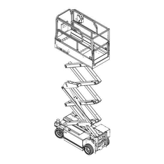
Meets requirements of CE. *Metric equivalent of working height adds 2 m (6.6 ft.) to platform height. **Weight may increase with certain options or country standards. "1532ES / 1932ES" Service & Parts Manual - CE Specifications February 2008 Page V... - Page 12 Brake Release (early models) Emergency Drive Motor Lowering Cable (Both Sides) Brake (current models) (Both Sides) Battery Pump Pothole Bar Charger Compartment (Both Sides) Ladder ART_2153 February 2008 "1532ES / 1932ES" Service & Parts Manual - CE Specifications Page VI...
-
Page 13: Primary Machine Components
2 | 3 | 5 | 6 Pothole Components Pothole Switch 2 | 5 | 6 Limit Switch 2 | 5 | 6 Lubrication Points intro Brake Release Hand Pump "1532ES / 1932ES" Service & Parts Manual - CE Specifications February 2008 Page VII... -
Page 14: Lubrication
Wheel Mount / Pivot Point Filler Cap with Strainer Fluid Level Sight Plastic Hydraulic Reservoir Gauge (late models) Return Filter Steel Hydraulic Reservoir (early models) ART_2154 February 2008 "1532ES / 1932ES" Service & Parts Manual - CE Specifications Page VIII... -
Page 15: Hydraulic System
Parking Brake and Towing Circuit ......................... 1-6 Emergency Systems And Procedures ........................1-7 Steering Circuit ............................... 1-8 Platform Lift Circuit ..............................1-9 Cylinder Repair ..............................1-10 Hydraulic Manifold ............................... 1-13 "1532ES / 1932ES" Service & Parts Manual - CE Specifications February 2008 Page 1-1... -
Page 16: Hydraulic Fluid
FLUID LEAKS UNDER PRESSURE MAY NOT ALWAYS BE VISIBLE. Fluid Recommendations MEC recommends the use of ISO Grade 32 hydraulic fluid. A 150SSU EQUIVALENT substitute can be used if absolutely necessary. Mineral-based hydraulic fluids produced by different compa- nies will USUALLY mix with each other satisfactorily, but this IS NOT RECOMMENDED. When in doubt, consult with your supplier. - Page 17 13. Check all leaks and correct as necessary. Machine is now ready to be placed back into operation. NOTE: Avoid mixing petroleum and synthetic base fluids. It is not advisable to mix fluids of different brands or types, except as recommended. "1532ES / 1932ES" Service & Parts Manual - CE Specifications February 2008 Page 1-3...
-
Page 18: Hydraulic System Components
Hydraulic Reservoior Sight Fluid Level Gauge Indicator Return Early Models are equipped with Filter a Welded Steel Hydraulic Reservoior Plastic Hydraulic Pump Hydraulic and Motor Reservoior ART_2160 February 2008 "1532ES / 1932ES" Service & Parts Manual - CE Specifications Page 1-4... - Page 19 Wheel Motor the two (2) front wheels. ART_2161 Braking Circuit Rear brakes are released whenever the machine is commanded to drive. Brake ART_2162 "1532ES / 1932ES" Service & Parts Manual - CE Specifications February 2008 Page 1-5...
-
Page 20: Parking Brake And Towing Circuit
♦ Close the tow valve by turning it clockwise. ♦ Brakes will reset when drive function is activated or reset by pulling on manual brake re- lease valve. February 2008 "1532ES / 1932ES" Service & Parts Manual - CE Specifications Page 1-6... -
Page 21: Emergency Systems And Procedures
To lower the platform, pull the red “T” handle located at the rear of the machine. Lowering stops when you release the “T” handle. ART_2163 "1532ES / 1932ES" Service & Parts Manual - CE Specifications February 2008 Page 1-7... -
Page 22: Steering Circuit
Refer to the Mechanical Section of this manual for cylinder disassembly, or replacement. Steer Cylinder Motor Mount Steer Pivot 1532ES / 1932ES ART_2164 February 2008 "1532ES / 1932ES" Service & Parts Manual - CE Specifications Page 1-8... -
Page 23: Platform Lift Circuit
(see Emergency Systems and Procedures ). "1532ES / 1932ES" Service & Parts Manual - CE Specifications February 2008 Page 1-9... -
Page 24: Cylinder Repair
1. Tag hoses for proper reassembly. 2. Disconnect hoses and IMMEDIATELY cap the openings to prevent contamination. 3. Remove cylinder from the machine as described in Section 4 . February 2008 "1532ES / 1932ES" Service & Parts Manual - CE Specifications Page 1-10... - Page 25 Scratches or pits deep enough to catch the fingernail are unacceptable; replace the cylinder. b. Polishing is a sign of uneven loading. Check for roundness. If a polished surface is not round within 0.18 mm replace the cylinder. "1532ES / 1932ES" Service & Parts Manual - CE Specifications February 2008 Page 1-11...
- Page 26 NOTE: It is very important to keep all parts clean when working with hydraulic cylinders, even one small piece of dirt or grit can damage the cylinder. February 2008 "1532ES / 1932ES" Service & Parts Manual - CE Specifications Page 1-12...
-
Page 27: Hydraulic Manifold
3. Connect hydraulic hoses (as previously tagged). Be certain to tighten hoses. 4. Connect the battery. 5. Operate each hydraulic function and check for proper operation and leaks. 6. Adjust valve pressures. "1532ES / 1932ES" Service & Parts Manual - CE Specifications February 2008 Page 1-13... - Page 28 February 2008 "1532ES / 1932ES" Service & Parts Manual - CE Specifications Page 1-14...
-
Page 29: Electrical System
Batteries .................................. 2-4 Alarms and Switches ............................. 2-8 Continuity Checks ..............................2-11 Diode Board ................................2-12 Sevcon Motor Speed Controller .......................... 2-13 Load Sensing System ............................2-14 "1532ES / 1932ES" Service & Parts Manual - CE Specifications February 2008 Page 2-1... -
Page 30: Electrical System - General
(Forward/Down, Reverse/Up and accelerator demand), Steer (Right/Left). A torque mode switch causes both hydraulic motors to operate in parallel rather than in series for speed control mode (normal). February 2008 "1532ES / 1932ES" Service & Parts Manual - CE Specifications Page 2-2... -
Page 31: Deutsch Connectors
♦ Insert the contact into the crimping tool and insert the stripped wire into the contact making sure no wires are outside the contact barrel. ♦ Close the handles of the crimping tool, then release the handles to remove the crimped contact. "1532ES / 1932ES" Service & Parts Manual - CE Specifications February 2008 Page 2-3... -
Page 32: Batteries
♦ “Wet” batteries should be kept fully charged. A “wet” battery, while in storage, should be recharged to full charge at recommended intervals. Leaving the MEC charger connected during prolonged storage will maintain battery voltage automatically. - Page 33 Battery Specific Gravity and Voltage Table SPECIFIC GRAVITY VOLTS DC 6V BATTERY 12V BATTERY EACH CELL PER CELL Fully Charged 1.280 2.10 6.30 12.60 Fully Discharged 1.130 1.75 5.19 10.50 "1532ES / 1932ES" Service & Parts Manual - CE Specifications February 2008 Page 2-5...
- Page 34 0 to 50 % charged Blinking 50 % to 75 % charged Blinking 75 % to 100 % charged Blinking 100 % charged Abnormal Cycle Blinking February 2008 "1532ES / 1932ES" Service & Parts Manual - CE Specifications Page 2-6...
- Page 35 To install the battery, reverse the process by posi- BATTERY tioning the battery in the compartment securely CHARGER with hold down bolts. Connect battery cables. 6 VDC BATTERY ART_2184 "1532ES / 1932ES" Service & Parts Manual - CE Specifications February 2008 Page 2-7...
-
Page 36: Alarms And Switches
It is activated at the upper controls and sounds at the ground alerting personnel to clear the machine’s path to avoid hazards or unsafe conditions. Horn (option) Terminal Block ART_2183 February 2008 "1532ES / 1932ES" Service & Parts Manual - CE Specifications Page 2-8... - Page 37 THE MOVEMENT ALARM IS PROVIDED FOR YOUR PROTECTION, AND PROTECTION OF PERSONS WORKING IN THE IMMEDIATE AREA. DISABLING THIS IMPORTANT SAFETY DEVICE MAY RESULT IN SERIOUS INJURY OR DEATH. "1532ES / 1932ES" Service & Parts Manual - CE Specifications February 2008 Page 2-9...
- Page 38 Base Controls. Elevate the platform to approximately 2.5 m. An alarm should sound at Upper Control station. If it does not, review Section 3 for troubleshooting of the Platform Overload Sensing System. February 2008 "1532ES / 1932ES" Service & Parts Manual - CE Specifications Page 2-10...
-
Page 39: Continuity Checks
♦ With one probe of ohm meter to common and other probe to closed contact, low resis- tance should be seen. Move limit switch arm and zero-to-very-low resistance should be seen. "1532ES / 1932ES" Service & Parts Manual - CE Specifications February 2008 Page 2-11... -
Page 40: Diode Board
Steer Right INPUT Lift Up 8601 INPUT Limit Switch (24V = platform down) OUTPUT Enable, from lower Lift switch OUTPUT To Sevcon (for speed cutback) ART_2181 February 2008 "1532ES / 1932ES" Service & Parts Manual - CE Specifications Page 2-12... -
Page 41: Sevcon Motor Speed Controller
(GROUND signal to activate Motor Start Relay) Lift Valve B- (provides GROUND signal to Lift Valve) none none Accelerator reference signal (3.6 Volts to Potentiometer) none none none none none none ART_2182 "1532ES / 1932ES" Service & Parts Manual - CE Specifications February 2008 Page 2-13... -
Page 42: Load Sensing System
Signal to Down Valve Coils Signal to Motor Controller (LIFT, DRIVE, STEER) Cutout Relay (B–) Cutout Relay (B+ when not overloaded) RL1 Overload Cutout Relay No Connection No Connection ART_2474 February 2008 "1532ES / 1932ES" Service & Parts Manual - CE Specifications Page 2-14... -
Page 43: Platform Overload System
GP102 - EZcal Help Messages .......................... 3-4 GP102 LED Flash Codes ..........................3-7 Calibration ................................3-8 CALIBRATION TROUBLESHOOTING; Failure Messages ................3-11 CALIBRATION TROUBLESHOOTING; Information Messages ................ 3-16 "1532ES / 1932ES" Service & Parts Manual - CE Specifications February 2008 Page 3-1... -
Page 44: General Description
In addition the automatic armguard cutout and descent alarm are controlled by this system. To access the control module for trouble- shooting and calibration, the EZcal hand held device is required. These are available from MEC Aerial Platform Sales Corp. -
Page 45: Electrical Connections
Lift, Drive, or Steer Function Wire 45 RL1-7 Cutout Relay B– Wire 44 RL1-8 Cutout Relay input (B+ when platform not overloaded) ART_2431 "1532ES / 1932ES" Service & Parts Manual - CE Specifications February 2008 Page 3-3... -
Page 46: Troubleshooting
• When the platform is not elevated, the measured height should be below that stored during load calibration All vehicle operation will be prevented until the problem is corrected. LED flash code 4. February 2008 "1532ES / 1932ES" Service & Parts Manual - CE Specifications Page 3-4... - Page 47 LED flash code 3. TESTING HWFS When the GP102 is powered up, it carries out various tests to ensure that it is functioning safely. "1532ES / 1932ES" Service & Parts Manual - CE Specifications February 2008 Page 3-5...
- Page 48 When the GP102 is powered up, all controls must be in neutral to allow safe testing of the fail-safe output; no functions are allowed until testing is complete. LED flash code 2. February 2008 "1532ES / 1932ES" Service & Parts Manual - CE Specifications Page 3-6...
-
Page 49: Gp102 Led Flash Codes
15 flash will be present whenever a new circuit board is installed previous to calibration. "1532ES / 1932ES" Service & Parts Manual - CE Specifications February 2008... -
Page 50: Calibration
Move machine to an area that is perfectly level as measured by a spirit level or other leveling device. An Ezcal hand-held device (MEC part # 90888) is required to carry out all calibration procedures on the GP102 Load sense control module. - Page 51 Note: The platform will lower incrementally during this phase on the calibration. Do not release the switch until fully lowered. Release switch. • Display reads TOTAL DATA #XX, then PLATFORM EMPTY? "1532ES / 1932ES" Service & Parts Manual - CE Specifications February 2008 Page 3-9...
- Page 52 • Display reads PLEASE LIFT. Hold lower controls switch in the up position until machine is fully elevated, then release switch. Display reads PLEASE LOWER. Hold switch in down position until platform is in the fully lowered position. Release switch. Display reads FINISHED. February 2008 "1532ES / 1932ES" Service & Parts Manual - CE Specifications Page 3-10...
-
Page 53: Calibration Troubleshooting; Failure Messages
DYNAMIC lift. The height sensor output must be between 1.0V and 4.0V. Check DIAGNOSTICS / SENSORS to see the output. A reading of 0V or 5V is probably due to a wiring problem. "1532ES / 1932ES" Service & Parts Manual - CE Specifications February 2008 Page 3-11... - Page 54 This message is given if the elevation switch (P2-10) closed during lower at a F18:LOW ELEV.CLOSE too low height (below 5%). Check CALIBRATIONS / HEIGHT CALS; the “ElevDown” value shows the recorded height where the switch opened. February 2008 "1532ES / 1932ES" Service & Parts Manual - CE Specifications Page 3-12...
- Page 55 This message occurs if too many static measurements are taken during a F24:TOO MANY calibration step. In the rare event that this occurs, please call MEC for assistance. F25:CHECK ELEV This message indicates a problem with the elevation switch (P2-10) during the F26:CHECK ELEV STATIC phases.
- Page 56 This message would occur if the pressure sensor was disconnected, or if there were some other wiring error. Check DIAGNOSTICS / SENSORS to check the pressure. February 2008 "1532ES / 1932ES" Service & Parts Manual - CE Specifications Page 3-14...
- Page 57 The height sensor output must be between 0.5V and 4.5V. Check DIAGNOSTICS / SENSORS to see the output. A reading of 0V or 5V is probably due to a wiring problem. "1532ES / 1932ES" Service & Parts Manual - CE Specifications February 2008 Page 3-15...
-
Page 58: Calibration Troubleshooting; Information Messages
This message is displayed during the STATIC loaded phase while the platform is LOWER LOADED being lowered to the next measurement height. This message is displayed during the DYNAMIC phase while the platform is LOWERING being lowered. February 2008 "1532ES / 1932ES" Service & Parts Manual - CE Specifications Page 3-16... - Page 59 If the previous DYNAMIC calibration was in error, or if the height or pressure sensor is replaced, it will be necessary to redo the DYNAMIC phase. "1532ES / 1932ES" Service & Parts Manual - CE Specifications February 2008 Page 3-17...
- Page 60 LOADED phase. If the previous LOADED calibration was in error, or if the pressure sensor is replaced, it will be necessary to redo the LOADED phase. February 2008 "1532ES / 1932ES" Service & Parts Manual - CE Specifications Page 3-18...
-
Page 61: Mechanical Components
Rear Wheel Brakes ............................4-7 Steer Cylinder ..............................4-8 Pothole Circuit ..............................4-9 Platform Removal ............................4-10 Lift Cylinder Removal and Installation ......................4-11 Scissor Beam Assembly ..........................4-12 "1532ES / 1932ES" Service & Parts Manual - CE Specifications February 2008 Page 4-1... -
Page 62: Torque Specifications
58 - 62 79 - 84 79 - 85 107 - 115 83 - 87 113 - 118 136-144 184 - 195 100 - 110 136 - 149 February 2008 "1532ES / 1932ES" Service & Parts Manual - CE Specifications Page 4-2... -
Page 63: Mechanical Components
1. Tag hoses for proper reassembly. 2. Disconnect hoses and IMMEDIATELY cap the openings to prevent contamination. 3. Torque hose fittings according to the Hydraulic Torque Specification Table. "1532ES / 1932ES" Service & Parts Manual - CE Specifications February 2008 Page 4-3... -
Page 64: Raising The Machine
5. Lower the machine to rest on the jack stands and inspect for stability. To lower the machine 1. Raise machine slightly and remove jack stands. 2. Lower the machine remove the jack. 3. Remove chocks. February 2008 "1532ES / 1932ES" Service & Parts Manual - CE Specifications Page 4-4... -
Page 65: Tires/Wheels
4. Install the replacement wheel and tighten the lug nuts. 5. Lower the machine to the ground. 6. Torque lug nuts to 102 to 115 Nm. 7. Remove the chocks. "1532ES / 1932ES" Service & Parts Manual - CE Specifications February 2008 Page 4-5... -
Page 66: Front Drive Motors
Installation is reverse of removal. TORQUE Ft. lbs. Lug Nuts 75 - 85 102 - 115 Motor Mount Bolts 65 - 72 88 - 97.5 ART_2186 Motor Shaft Nut February 2008 "1532ES / 1932ES" Service & Parts Manual - CE Specifications Page 4-6... -
Page 67: Rear Wheel Brakes
Lug Nuts 75 - 85 102 - 115 Brake Mount Bolts 65 - 72 88 - 97.5 “T” Fitting (male-male-female) Female to Male Hose Adapter ART_2188 "1532ES / 1932ES" Service & Parts Manual - CE Specifications February 2008 Page 4-7... -
Page 68: Steer Cylinder
♦ when all air is purged, tighten hose connections. Steer Cylinder Seal Replacement Refer to Section 1 for seal replacement instruc- tions. 1532ES / 1932ES ART_2164 February 2008 "1532ES / 1932ES" Service & Parts Manual - CE Specifications Page 4-8... -
Page 69: Pothole Circuit
Lock Nut Lock Nut Spring Pothole Bar Weldment Roller Flat Washer Pothole Bar Snap Ring Assembly Wear Block Flat Washer Spacer Actuator Plate Flat Washer ART_2189 "1532ES / 1932ES" Service & Parts Manual - CE Specifications February 2008 Page 4-9... -
Page 70: Platform Removal
8. Installation is reverse of removal. Horn (option) Terminal Srtip Cover Slide Block Fixed Block TORQUE Ft. lbs. Fixed Block Bolts 86 - 96 116 - 180 ART_2202 February 2008 "1532ES / 1932ES" Service & Parts Manual - CE Specifications Page 4-10... -
Page 71: Lift Cylinder Removal And Installation
10. Installation is reverse Lift of removal. Cylinder Nylon Washer Support Beam Retaining Nylon Ring Washer TORQUE Ft. lbs. ART_2203 Retaining Plate Bolts 6¼ - 7¼ 8.5 - 10 "1532ES / 1932ES" Service & Parts Manual - CE Specifications February 2008 Page 4-11... -
Page 72: Scissor Beam Assembly
Bearing Wear TORQUE Ft. lbs. Stationary Mount Bolts 86 - 96 116 - 180 Slide Block ART_2204 Ladder Mount Bolts 86 - 96 116 - 180 February 2008 "1532ES / 1932ES" Service & Parts Manual - CE Specifications Page 4-12... -
Page 73: Troubleshooting
Sevcon Motor Speed Controller .......................... 5-14 LED Diagnostics Definitions (Flash Codes) ..................... 5-15 Sevcon Motor Speed Controller - Connections ....................5-17 Troubleshooting Battery Charger ........................5-19 "1532ES / 1932ES" Service & Parts Manual - CE Specifications February 2008 Page 5-1... -
Page 74: General Troubleshooting Tips
♦ Steering flow control valve PFC1 and relief valve RV3 are replaced by a single valve FRR1. Refer to the accompanying illustrations when using the Troubleshooting Guide. February 2008 "1532ES / 1932ES" Service & Parts Manual - CE Specifications Page 5-2... - Page 75 Early Models MAIN MANIFOLD (Early Models) TEST MV1 CV1 PORT PFC1 CBV1 MAIN MANIFOLD (Current Models) TEST PORT FRR1 CBV1 Hydraulic Valve Locations, 1532ES - 1932ES ART_2476 "1532ES / 1932ES" Service & Parts Manual - CE Specifications February 2008 Page 5-3...
-
Page 76: Hydraulic Pressure Adjustment Procedures
♦ When correct pressure is obtained replace tamper proof cap with a new one. CAUTION: Do not operate pump with tamper proof cap removed as fluid will emit under pressure. February 2008 "1532ES / 1932ES" Service & Parts Manual - CE Specifications Page 5-4... - Page 77 ♦ Turn adjustment screw “IN” to increase the pressure. ♦ Turn adjustment screw “OUT” to decrease the pressure. ♦ When correct pressure is obtained replace tamper proof cap with a new one. "1532ES / 1932ES" Service & Parts Manual - CE Specifications February 2008 Page 5-5...
-
Page 78: Troubleshooting
(if Check cable adjustment/operation (if equipped) equipped) sticking 6- flash code at motor controller Test potentiometer POT1 for open circuit Located in upper control box, replace February 2008 "1532ES / 1932ES" Service & Parts Manual - CE Specifications Page 5-6... -
Page 79: Troubleshooting
Clean orifice - located under fitting at lift cylinder Emergency E-down cable freyed (later replace e-down cable lowering not models only) working Lowering valve not shifting Clean debris, replace "1532ES / 1932ES" Service & Parts Manual - CE Specifications February 2008 Page 5-7... - Page 80 Check valves for contanimation, replace SV4 or SV6 drive either One or both Wheel motors WM1 Test wheel motors direction Torque & WM2 internal bi-pass Replace wheel motors switch ON February 2008 "1532ES / 1932ES" Service & Parts Manual - CE Specifications Page 5-8...
- Page 81 Drive valve SV3 sticking Check SV3 for contanimation direction Replace SV3 regardless of Drive valve SV3 powered in one Short in wiring, faulty diode board direction direction operated "1532ES / 1932ES" Service & Parts Manual - CE Specifications February 2008 Page 5-9...
- Page 82 Check wire 7 through plug connections from upper NOT operating connection control box to Diode Board while attempting to Failed diode in diode board Test diodes on diode board steer Replace diode board February 2008 "1532ES / 1932ES" Service & Parts Manual - CE Specifications Page 5-10...
- Page 83 Steer valve SV1 sticking Inspect SV1 valve for debris direction Replace SV1 regardless of Drive valve SV1 powered in one Short in wiring, faulty diode board. direction direction request "1532ES / 1932ES" Service & Parts Manual - CE Specifications February 2008 Page 5-11...
- Page 84 5] Horn Button (option) 6] Steering Micro-Switches 7] Drive Enable Switch 8] Reverse/Down Rocker Switch 9] Forward/Up Rocker Switch 10] Potentiometer 11] Terminal Strip ART_2429 12] Control Box Alarm February 2008 "1532ES / 1932ES" Service & Parts Manual - CE Specifications Page 5-12...
- Page 85 2] Contactor 14] Hour Meter 3] Circuit (Diode) Board 15] GP102 Load Sense Module 4] Battery Cutoff Switch 16] Overload Cutout Relay 5] MotorControl Unit ART_2428 "1532ES / 1932ES" Service & Parts Manual - CE Specifications February 2008 Page 5-13...
-
Page 86: Sevcon Motor Speed Controller
(GROUND signal to activate Motor Start Relay) Lift Valve B- (provides GROUND signal to Lift Valve) none none Accelerator reference signal (3.6 Volts to Potentiometer) none none none none none none ART_2182 February 2008 "1532ES / 1932ES" Service & Parts Manual - CE Specifications Page 5-14... -
Page 87: Led Diagnostics Definitions (Flash Codes)
Worn motor brushes • Incomplete circuit to the Sevcon pin #6 If the motor and contactor circuits are diagnosed as working properly: • Sevcon internal fault continued… "1532ES / 1932ES" Service & Parts Manual - CE Specifications February 2008 Page 5-15... - Page 88 This code will interrupt or prevent lift function but will allow drive and steer functions When lift is interrupted due to a 9 flash, the electric motor will still run. February 2008 "1532ES / 1932ES" Service & Parts Manual - CE Specifications Page 5-16...
-
Page 89: Sevcon Motor Speed Controller - Connections
Speed cut-back Full speed: 24 V DC signal from limit Creep speed: 0 V DC. switch or Lift • Speed cut-back is the elevated drive speed circuit "1532ES / 1932ES" Service & Parts Manual - CE Specifications February 2008 Page 5-17... - Page 90 • 0 volts at idle = 3 flash code • Above 20 volts at idle = 4 flash code • No voltage change after Motor Start Relay signal = 5 flash code February 2008 "1532ES / 1932ES" Service & Parts Manual - CE Specifications Page 5-18...
-
Page 91: Troubleshooting Battery Charger
The MEC battery charger is a fully automatic type with a maintenance feature that will maintain battery voltage indefinately when connected to an AC power source. The battery charger should be plugged into an unswitched AC source if stored for long periods of time. - Page 92 5.) The AC supply circuit breaker or fuse is blown If the problem is not listed above, refer the problem to a qualified service agent for additional trouble shooting procedures. February 2008 "1532ES / 1932ES" Service & Parts Manual - CE Specifications Page 5-20...
- Page 93 Replace batteries • Battery pack too large for charger. Use higher output charger or unplug then plug-in charger to restart charge cycle to complete charging "1532ES / 1932ES" Service & Parts Manual - CE Specifications February 2008 Page 5-21...
- Page 94 • If the charger operates properly on other AC outlets, a qualified Person should correct the AC outlet problem • If the AC supply checks good, the charger should be replaced February 2008 "1532ES / 1932ES" Service & Parts Manual - CE Specifications Page 5-22...
-
Page 95: Schematics
Electric Schematics ............................... 6-9 1532ES, S/N 9000500 - 9001099 1932ES, S/N 9104000 - 9104999 ......................6-10 1532ES, S/N 9002000 - Current 1932ES, S/N 9105000 - Current ........................ 6-12 "1532ES / 1932ES" Service & Parts Manual - CE Specifications February 2008 Page 6-1... -
Page 96: Hydraulic Schematics
Lift Cylinder Manifold (MA-3) Test Port Main Manifold (MA-1) Wheel Brake Drive Wheel Wheel Brake Drive Wheel Wheel Motor, Right Side Machine Base Wheel Motor, Left Side Machine Base February 2008 "1532ES / 1932ES" Service & Parts Manual - CE Specifications Page 6-2... - Page 97 ø.040 WHEEL MOTOR PORT “B” CBV1 1500 PSI PORT “B” LEFT WHEEL MOTOR 5 PSI PORT “A” 2400 PSI 1932ES 1900 PSI 1532ES TP−1 2750 PSI "1532ES / 1932ES" Service & Parts Manual - CE Specifications February 2008 Page 6-3...
-
Page 98: 1532Es - Serial # 9001100 - Current 1932Es - Serial # 9105000 - Current
Spool Valve, Down Lift Cylinder Manifold (MA-2) Wheel Brake Drive Wheel Wheel Brake Drive Wheel Wheel Motor, Right Side Machine Base Wheel Motor, Left Side Machine Base February 2008 "1532ES / 1932ES" Service & Parts Manual - CE Specifications Page 6-4... - Page 99 STEERING CYLINDER CYL1 BRAKES MA−1 ORF2 ø.040 RIGHT ORF1 WHEEL ø.040 2400 MOTOR FRR1 1.0 GPM 850 PSI LEFT WHEEL 1500 PSI MOTOR 2750 PSI CBV1 "1532ES / 1932ES" Service & Parts Manual - CE Specifications February 2008 Page 6-5...
- Page 100 SV9 Spool Valve Emergency Lowering A12 Pressure Sensor Overload SOL2 SOL8 SOL3 SOL10 TEST SOL6 PORT SOL7 SOL1 SOL5 SOL8 SOL2 PFC1 CBV1 ORF1 SOL4 SOL9 February 2008 "1532ES / 1932ES" Service & Parts Manual - CE Specifications Page 6-6...
- Page 101 Down, Lift Cylinder SOL3 SOL1 A12 Pressure Sensor Overload SOL4 SOL5 SOL6 SOL2 SOL8 SOL3 SOL5 SOL1 SOL4 SOL2 SOL7 SOL6 SOL8 CBV1 ORF1 PLUG FRR1 ORF2 "1532ES / 1932ES" Service & Parts Manual - CE Specifications February 2008 Page 6-7...
- Page 102 THIS PAGE INTENTIONALLY LEFT BLANK February 2008 "1532ES / 1932ES" Service & Parts Manual - CE Specifications Page 6-8...
-
Page 103: Electric Schematics
2 meters. 4. Switch LS2 closes the N/C set of contacts when the Pothole Bars are down and locked in place. ART_2236 ART_2243 "1532ES / 1932ES" Service & Parts Manual - CE Specifications February 2008 Page 6-9... -
Page 104: 1532Es, S/N 9000500 - 9001099 1932Es, S/N 9104000 - 9104999
Activate Brake Valve (SV7) Main Manifold SOL10 Coil, Down Solenoid Activate Down Valve (SV8) Main Manifold SOL11 Coil, Down Solenoid Activate Down Valve (SV9) Lift Cylinder Manifold February 2008 "1532ES / 1932ES" Service & Parts Manual - CE Specifications Page 6-10... - Page 105 B+ B− (MOTOR CONTROLLER) SOL2 SOL1 STEER SOL5 TORQUE 200 AMP RIGHT LEFT SOL6 TORQUE SOL3 DECEL SOL9 MAIN BRAKE CHRL 1 MANIFOLD B1−B4 P N G "1532ES / 1932ES" Service & Parts Manual - CE Specifications February 2008 Page 6-11...
-
Page 106: 1532Es, S/N 9002000 - Current 1932Es, S/N 9105000 - Current
Activate Reverse Valve (SV3) Main Manifold SOL8 Coil, Forward Solenoid Activate Forward Valve (SV3) Main Manifold SOL11 Coil, Down Solenoid Activate Down Valve (SV9) Lift Cylinder Manifold February 2008 "1532ES / 1932ES" Service & Parts Manual - CE Specifications Page 6-12... - Page 107 J−5 SOL1 SOL2 P5−1 B+ B− RIGHT LEFT (MOTOR CONTROLLER) SOL5 TORQUE 200 AMP SOL3 SOL6 BRAKE/DECEL TORQUE MAIN MANIFOLD CHRL 1 B1−B4 P N G "1532ES / 1932ES" Service & Parts Manual - CE Specifications February 2008 Page 6-13...
- Page 108 WIRE # END VIEW OF D1 − D15 REMOVABLE CONTROL HARNESS R1 − R4 (OPTIONAL QUICK DISCONNECT) 16 (GND) TERMINAL BLOCK ON UNDERSIDE OF PLATFORM DECK February 2008 "1532ES / 1932ES" Service & Parts Manual - CE Specifications Page 6-14...
- Page 109 Component Locations Model: / Serial # 1532ES - 1932ES: all CE Reference Art #: none Publication Art #: ART_2446 REFER TO ELECTRIC SCHEMATIC Terminal Block "1532ES / 1932ES" Service & Parts Manual - CE Specifications February 2008 Page 6-15...
- Page 110 LIFT CYLINDER MAIN MANIFOLD CURRENT MODELS STEER RIGHT STEER LEFT SOL1 SOL2 TORQUE SOL5 SOL4 SOL3 SOL12 DECEL LIFT SOL6 SOL7 TORQUE SOL8 FORWARD REVERSE DRIVE February 2008 "1532ES / 1932ES" Service & Parts Manual - CE Specifications Page 6-16...
- Page 111 INPUT Steer Right INPUT Lift Up INPUT Limit Switch (24V = platform down) OUTPUT Enable, from lower Lift switch 8601 OUTPUT To Sevcon (for speed cutback) "1532ES / 1932ES" Service & Parts Manual - CE Specifications February 2008 Page 6-17...
- Page 112 P6-12 GP-102 (J3 - Pin 4) GP-102 (J3 - Pin 5) Inside Lower Control Box RL1 Overload Cutout Relay No Connection No Connection Overload Cutout Relay February 2008 "1532ES / 1932ES" Service & Parts Manual - CE Specifications Page 6-18...
- Page 113 , 25237................... C-15 YLINDER , 90801 W ......C-17 YLINDER ITHOUT MERGENCY OWERING ABLE , 90801 W .......C-19 YLINDER MERGENCY OWERING ABLE , 91055 W .......C-21 YLINDER MERGENCY OWERING ABLE "1532ES / 1932ES" Service & Parts Manual - CE Specifications February 2008...
-
Page 114: Parts Section
ECALS ONTROLS , 1532ES - 1932ES B ..............F-5 ECALS , 1532ES - 1932ES S ............. F-7 ECALS CISSORS , 1532ES - 1932ES P ............F-9 ECALS LATFORM February 2008 "1532ES / 1932ES" Service & Parts Manual - CE Specifications... - Page 115 THER ARLY ODELS ) ............. A-21 ARNESSES OMMUNICATION ABLE URRENT ODELS ) ............A-21 ARNESSES PPER ONTROLS URRENT ODELS ) ................A-21 ARNESSES THER URRENT ODELS "1532ES - 1932ES" Service & Parts Manual - CE Specifications February 2008 Page A-1...
- Page 116 WIRE # OVERLOAD/TILT 16 (GND) END VIEW OF REMOVABLE CONTROL HARNESS TERMINAL BLOCK ON UNDERSIDE OF PLATFORM DECK Upper Control Box, Removable, ES Machines, CE ART_2224 February 2008 "1532ES - 1932ES" Service & Parts Manual - CE Specifications Page A-2...
-
Page 117: Removable Control Box Assembly
LIGHT, BAYONET, 28 VOLT 8044 SWITCH, (MANUAL HORN) (OPTION) 8819 BOOT (OPTION) CABLE, UPPER CONTROL (SEE WIRE HARNESS) 6318 PIN REPAIR KIT FOR CABLE 7553 CONTROL BOX ALARM "1532ES - 1932ES" Service & Parts Manual - CE Specifications February 2008 Page A-3... - Page 118 HORN BUTTON ____ TORQUE ____ COLOR WIRE # OVERLOAD/TILT 16 (GND) TERMINAL BLOCK ON UNDERSIDE OF PLATFORM DECK Upper Control Box, Fixed, ES Machines, CE ART_2225 February 2008 "1532ES - 1932ES" Service & Parts Manual - CE Specifications Page A-4...
-
Page 119: Fixed Control Box Assembly
LIGHT, BAYONET, 28 VOLT 8044 SWITCH, (MANUAL HORN) (OPTION) 8819 BOOT (OPTION) CONTROL CABLE (SEE WIRE HARNESS) 16079 STRAIN RELIEF WASHER 16120 MOUNTING PLATE 7553 CONTROL BOX ALARM "1532ES - 1932ES" Service & Parts Manual - CE Specifications February 2008 Page A-5... - Page 120 TO CONTROL BOX Control Box Cover Assembly, ES Machines Reference: ART_13868 ART_2220 February 2008 "1532ES - 1932ES" Service & Parts Manual - CE Specifications Page A-6...
-
Page 121: Upper Control Box Cover Assembly
PLATE, STRAP 3766 PLATE, TOP 7819 BEARING, BRONZE, FLANGED 8435 SPRING, JOYSTICK, CENTERING 13527 POTENTIOMETER ASSEMBLY (INCLUDES 21, 22, & 23) 8346 WIRE HARNESS (NOT SHOWN) "1532ES - 1932ES" Service & Parts Manual - CE Specifications February 2008 Page A-7... - Page 122 Control Arm (Joystick) Reference: ART_188 ART_2221 February 2008 "1532ES - 1932ES" Service & Parts Manual - CE Specifications Page A-8...
-
Page 123: Joystick
8089 WIRE, BLK 18GA 300 V 7777 TERMINAL, PUSH ON, 3/16" 8447 SWITCH SEPARATOR (SERVICE ONLY) 8753 MOTION SWITCH, ON-OFF (SERVICE ONLY) 8448 SWITCH (SERVICE ONLY) "1532ES - 1932ES" Service & Parts Manual - CE Specifications February 2008 Page A-9... - Page 124 104A Base Controls Panel, ES Machines Reference: ART_925 ART_2222 February 2008 "1532ES - 1932ES" Service & Parts Manual - CE Specifications Page A-10...
-
Page 125: Lower Control Panel
BLOCK, CONTACT, N.C. (ABB) 7235 CIRCUIT BREAKER, 15 AMP 7099 BATTERY GAUGE, 24 VOLT (OPTIONAL) 7115 PLUG (IF BATTERY GAUGE IS NOT PRESENT) 7909 METER, HOUR "1532ES - 1932ES" Service & Parts Manual - CE Specifications February 2008 Page A-11... - Page 126 Base Controls, ES Machines, CE ART_2226 February 2008 "1532ES - 1932ES" Service & Parts Manual - CE Specifications Page A-12...
-
Page 127: Lower Control Box
BRKT, CONTROL BOX MOUNT HDW5417 SCREW HDW6432 SCREW 1532ES - SERIAL # 9001011 - UP 1932ES - SERIAL # 9104542 - UP 16609 WELDMENT, BASE CONTROL BOX CONTINUED... "1532ES - 1932ES" Service & Parts Manual - CE Specifications February 2008 Page A-13... - Page 128 Base Controls, ES Machines, CE ART_2226 February 2008 "1532ES - 1932ES" Service & Parts Manual - CE Specifications Page A-14...
- Page 129 90925 ADAPTER, RECEPTACLE HOLE 7115 HOLE PLUG 90927 RELAY, SPDT 24VDC 90871 RELAY, BASE 90923 RELAY, CLIP 16064 BRACKET, LOAD SENSE 90843 GP102 LOAD SENSE MODULE "1532ES - 1932ES" Service & Parts Manual - CE Specifications February 2008 Page A-15...
- Page 130 Charger Pump Motor + Pump Motor − Charger Harnesses and Cables, Lower Control Box, X32ES and X33ES, CE ART_2450 February 2008 "1532ES - 1932ES" Service & Parts Manual - CE Specifications Page A-16...
-
Page 131: Wire Harnesses , Lower Controls
WIRE, 14 GA, CE COLORS 90156 AS REQ TERMINAL, PUSH ON, 1/4" MALE FI, 22-18 9356 CLAMP, NYLON 90781 FORK TERMINAL 12 GA 90877 HARNESS, INSTRUMENT "1532ES - 1932ES" Service & Parts Manual - CE Specifications February 2008 Page A-17... - Page 132 TERMINAL BLOCK ON UNDERSIDE OF PLATFORM DECK Control Cable and Manifold Harness, ES Series, CE ART_2448 February 2008 "1532ES - 1932ES" Service & Parts Manual - CE Specifications Page A-18...
-
Page 133: Wire Harnesses , Communication Cable (Early Models
SAFETY SWITCH HARNESS (NOT SHOWN) — HORN (OPTION) SEE SECTION B — POWER CONVERTER (OPTION) SEE SECTION E, OPTIONS 90870 HARNESS, LOAD SENSE BOARD 90878 HARNESS, LOAD SENSE TRANSDUCERS "1532ES - 1932ES" Service & Parts Manual - CE Specifications February 2008 Page A-19... - Page 134 TERMINAL BLOCK ON UNDERSIDE OF PLATFORM DECK Control Cable and Manifold Harness, ES Series, CE ART_2449 February 2008 "1532ES - 1932ES" Service & Parts Manual - CE Specifications Page A-20...
-
Page 135: Wire Harnesses , Communication Cable (Current Models
LIFT CYLINDER HARNESS, DOWN VALVE (NOT SHOWN) — HORN (OPTION) SEE SECTION B — POWER CONVERTER (OPTION) SEE SECTION E, OPTIONS 90870 HARNESS LOAD SENSE BOARD 90878 HARNESS LOAD SENSE TRANSDUCERS "1532ES - 1932ES" Service & Parts Manual - CE Specifications February 2008 Page A-21... - Page 136 February 2008 "1532ES - 1932ES" Service & Parts Manual - CE Specifications Page A-22...
- Page 137 ......................B-13 OLLOUT OLLER ........................B-15 ERMINAL LOCK (CE O ) ....................B-15 PERATOR PTION ) ....................B-15 IRLINE LATFORM PTION ........................ B-17 OWER TO LATFORM "1532ES / 1932ES" Service & Parts Manual - CE Specifications February 2008 Page B-1...
- Page 138 Work Platform, Main Deck, X32ES, CE Reference: ART_684 ART_2452 February 2008 "1532ES / 1932ES" Service & Parts Manual - CE Specifications Page B-2...
-
Page 139: Latform And Ails
SCREW, 5/16" - 18, 3/4" LG 13778 BLOCK, SLIDE, PLATFORM 13637 BRACKET, ROLLER COVER 3923 BRKT, ATTACHMENT POINT HDW6432 SCREW, 3/8" - 16, 3/4" LG HDW5039 LOCK NUT, 3/8" - 16 "1532ES / 1932ES" Service & Parts Manual - CE Specifications February 2008 Page B-3... - Page 140 Extension Deck, X32 ES Reference: ART_683 ART_2250 February 2008 "1532ES / 1932ES" Service & Parts Manual - CE Specifications Page B-4...
-
Page 141: Rollout Deck And Rails
SCREW, 1/4" - 20, 3/4" LG HDW7471 SCREW, 5/16" - 18, 3" LG 25499 PLATFORM EXTENSION WELDMENT HDW8486 SCREW, 5/16" - 18, 1 7/8" LG HDW8304 NUT, 5/16" - 18 "1532ES / 1932ES" Service & Parts Manual - CE Specifications February 2008 Page B-5... - Page 142 Entry Rail, X32ES Reference: ART_685 ART_2451 February 2008 "1532ES / 1932ES" Service & Parts Manual - CE Specifications Page B-6...
-
Page 143: Ntry Ate
3 FT. PAD, RAIL (OPTION ONLY) 25051 GATE, SHEET LOAD HDW90792 PIN, LOCK, 5/16" HDW7119 SCREW, 5/16" - 18, 2 1/4" LG HDW8304 NUT, 3/8" - 16 "1532ES / 1932ES" Service & Parts Manual - CE Specifications February 2008 Page B-7... - Page 144 Swing Gate, X32ES - X33ES Reference: ART_ ART_2253 February 2008 "1532ES / 1932ES" Service & Parts Manual - CE Specifications Page B-8...
-
Page 145: Wing Gate
HEX CAP SCREW 5/16"-18 X 2.25" HDW8294 FLAT WASHER 0.328 ID HDW8304 LOCNUT 5/16"-18 HDW5724 HEX CAP SCREW 5/16"-18 X 3/4" HDW5217 FLAT WASHER 11/32" ID "1532ES / 1932ES" Service & Parts Manual - CE Specifications February 2008 Page B-9... - Page 146 Roll-out Deck Lock Pin Assembly Reference ART_686 ART_2174 February 2008 "1532ES / 1932ES" Service & Parts Manual - CE Specifications Page B-10...
-
Page 147: Rollout Deck Lock
SCREW, 5/16" - 18, 2" LG HDW8304 NUT, 5/16" - 18 HDW8513 SPRING PIN, 1/8" DIA, 3/4" LG HDW7031 WASHER, 1/2" ID, 7/8" OD 7408 SPRING, DECK LOCK "1532ES / 1932ES" Service & Parts Manual - CE Specifications February 2008 Page B-11... - Page 148 Roll-out Deck Roller Reference: ART_687 ART_2095 February 2008 "1532ES / 1932ES" Service & Parts Manual - CE Specifications Page B-12...
-
Page 149: Rollout Deck Roller
ITEM PART NO. DESCRIPTION OLLOUT OLLER 5918 RING, RETAINING, HEAVY DUTY 1" HDW8370 WASHER 13230 ROLLER 13267 ROLLER PLATE WELDMENT "1532ES / 1932ES" Service & Parts Manual - CE Specifications February 2008 Page B-13... - Page 150 Connect Horn Wires to Terminals #6 and #9 Terminal Block Installation, ES ART_2227 February 2008 "1532ES / 1932ES" Service & Parts Manual - CE Specifications Page B-14...
-
Page 151: Erminal Lock
CABLE TIE 8543 HOSE, 1/4" AIRLINE * 1532ES = 27 FT. * 1932ES = 33 FT. 8559 CLAMP, HOSE HDW5052 FITTING, 1/4" MALE, MALE HOSE BARB "1532ES / 1932ES" Service & Parts Manual - CE Specifications February 2008 Page B-15... - Page 152 Power to Platform Outlet Installation ART_2228 February 2008 "1532ES / 1932ES" Service & Parts Manual - CE Specifications Page B-16...
-
Page 153: Power To Platform
SCREW, 5/16–18 × ¾" HDW8304 NUT, 5/16–18 HDW8501 CLIP, SELF RETAINING 7617 WIRE, 14 GA 28 FT *1532ES 35 FT * 1932ES HDW5217 FLAT WASHER 11/32" ID "1532ES / 1932ES" Service & Parts Manual - CE Specifications February 2008 Page B-17... - Page 154 February 2008 "1532ES / 1932ES" Service & Parts Manual - CE Specifications Page B-18...
- Page 155 , 90801 W ............ C-17 YLINDER ITHOUT MERGENCY OWERING ABLE , 90801 W ............C-19 YLINDER MERGENCY OWERING ABLE , 91055 W ............C-21 YLINDER MERGENCY OWERING ABLE "1532ES / 1932ES" Service & Parts Manual - CE Specifications February 2008 Page C-1...
- Page 156 DENOTES LOCATION OF HDW3802. Scissor Assembly, 1532ES, CE Reference: ART_ ART_2453 February 2008 "1532ES / 1932ES" Service & Parts Manual - CE Specifications Page C-2...
-
Page 157: Scissors Assembly , 1532Es
LIFT CYLINDER (SEE END OF THIS SECTION) 25454 MAINTENANCE LOCK 8907 BEARING, MSI2832-24 25219 RETAINING PLATE CYL PIN 25142 PIN, CYLINDER MOUNT (CONTINUED ON NEXT PAGE) "1532ES / 1932ES" Service & Parts Manual - CE Specifications February 2008 Page C-3... - Page 158 DENOTES LOCATION OF HDW3802. Scissor Assembly, 1532ES, CE Reference: ART_ ART_2453 February 2008 "1532ES / 1932ES" Service & Parts Manual - CE Specifications Page C-4...
- Page 159 WASHER, FLAT NYLATRON 25427 BLOCK, SLIDE BASE 90844 ANGLE SENSOR HDW6831 SCREW, 1/4" - 20 X 2 7041 HOSE CLAMP 9146 HOSE CLAMP 90765 11.5' CABLE WRAP "1532ES / 1932ES" Service & Parts Manual - CE Specifications February 2008 Page C-5...
- Page 160 DENOTES LOCATION OF HDW3802. Scissor Assembly, 1932ES, CE Reference: ART_ ART_2454 February 2008 "1532ES / 1932ES" Service & Parts Manual - CE Specifications Page C-6...
-
Page 161: Scissors Assembly , 1932Es
LIFT CYLINDER (SEE END OF THIS SECTION) 25454 MAINTENANCE LOCK 8907 BEARING, MSI2832-24 25219 RETAINING PLATE CYL PIN 25142 PIN, CYLINDER MOUNT 25429 SPACER RUBBER (CONTINUED ON NEXT PAGE) "1532ES / 1932ES" Service & Parts Manual - CE Specifications February 2008 Page C-7... - Page 162 DENOTES LOCATION OF HDW3802. Scissor Assembly, 1932ES, CE Reference: ART_ ART_2454 February 2008 "1532ES / 1932ES" Service & Parts Manual - CE Specifications Page C-8...
- Page 163 WASHER, FLAT NYLATRON 25427 BLOCK, SLIDE BASE 90844 ANGLE SENSOR HDW6831 SCREW, 1/4" - 20 X 2 7041 HOSE CLAMP 9146 HOSE CLAMP 90765 11.5' CABLE WRAP "1532ES / 1932ES" Service & Parts Manual - CE Specifications February 2008 Page C-9...
- Page 164 Scissor Mounting Detail, X32ES Reference: ART_ ART_2262 February 2008 "1532ES / 1932ES" Service & Parts Manual - CE Specifications Page C-10...
-
Page 165: Scossors Mount
BLOCK, SLIDE BASE 25173 PIN WELDMENT STATIONARY MOUNT HDW8283 SCREW, 1/2-13, 1.5 LG, GR 8 HDW8457 NUT, LOCK, 1/2-13 HDW13175 WASHER, NYLON, 2.06 ID, 2.62 OD, .030 THK "1532ES / 1932ES" Service & Parts Manual - CE Specifications February 2008 Page C-11... - Page 166 Cylinder Mounting Detail, ES Reference: ART_ ART_2265 February 2008 "1532ES / 1932ES" Service & Parts Manual - CE Specifications Page C-12...
-
Page 167: Lift Cylinder Mount
25142 PIN, 1.373 X 5.382 CYL MOUNT 6984 BEARING, 1.375 X 1.625 LG 6669 BEARING, 2.0 X 2.0 LG 6875 RETAINING RING, 1.375 DIA. LIFT CYLINDER "1532ES / 1932ES" Service & Parts Manual - CE Specifications February 2008 Page C-13... - Page 168 L I F 1532ES, CE: Serial # 9001000 - 9001008 25237 Hydraulic Cylinder, CE ART_2455 1932ES, CE: Serial # 9100000 - 9104470 February 2008 "1532ES / 1932ES" Service & Parts Manual - CE Specifications Page C-14...
-
Page 169: Lift Cylinder , 25237
BEARING, DU, 1 3/8" ID X 1 5/8" LG 7788 CLAMP, HOSE 90439 ORIFICE 0.047 (1932ES) 90889 ORIFICE 0.055 (1532ES) 90845 PRESSURE SENSOR 3000 PSI HARNESS, WIRE DOWN, VALVE (SEE PARTS SECTION E) "1532ES / 1932ES" Service & Parts Manual - CE Specifications February 2008 Page C-15... - Page 170 L I F 1532ES CE: Serial # 9001009 - 9001031 90801 Hydraulic Clyinder, CE ART_2456 1932ES CE: Serial # 9104471 - 9105000 February 2008 "1532ES / 1932ES" Service & Parts Manual - CE Specifications Page C-16...
-
Page 171: Ift Ylinder Ithout Mergency Owering Able
CLAMP, HOSE 90845 PRESSURE SENSOR 3000 PSI 16162 BRACKET, LIFT CYLINDER VALVE GUARD HDW8152 SCREW, 1/4–20 X 3/4 HARNESS, WIRE, DOWN VALVE (SEE PARTS SECTION A) "1532ES / 1932ES" Service & Parts Manual - CE Specifications February 2008 Page C-17... - Page 172 I F O Emergency Lowering Cable - 1532ES-1932ES 1532ES CE: Serial # 9001009 - 9001047 90801 Hydraulic Clyinder, CE ART_2457 1932ES CE: Serial # 9104470 - 9105458 February 2008 "1532ES / 1932ES" Service & Parts Manual - CE Specifications Page C-18...
-
Page 173: Lift Cylinder , 90801 With Emergency Lowering Cable
CAP LUG 16117 WELDMENT, CABLE MOUNT ATTACHMENT 8152 BOLT 16121 BELL CRANK — CLEVIS PIN — COTTER PIN 16134 E-DOWN PIVOT NUT 90845 PRESSURE SENSOR 3000 PSI "1532ES / 1932ES" Service & Parts Manual - CE Specifications February 2008 Page C-19... - Page 174 L I F I F O Emergency Lowering Cable - 1532ES-1932ES 1532ES CE: Serial # 9001048 UP 91055 Hydraulic Clyinder, CE ART_2458 1932ES CE: Serial # 9105459 UP February 2008 "1532ES / 1932ES" Service & Parts Manual - CE Specifications Page C-20...
-
Page 175: Ift Ylinder Ith Mergency Owering Able
91082 CABLE, 100 IN 91104 CABLE. 80 IN — SPRING — CAP LUG 16062 BRACKET, LIFT CYLINDER VALVE GUARD 8152 BOLT 90845 PRESSURE SENSOR 3000 PSI "1532ES / 1932ES" Service & Parts Manual - CE Specifications February 2008 Page C-21... - Page 176 February 2008 "1532ES / 1932ES" Service & Parts Manual - CE Specifications Page C-22...
- Page 177 ..................D-9 ANIFOLD SSEMBLY ODELS ....................D-11 YDRAULIC ESERVOIR TEEL ....................D-13 YDRAULIC ESERVOIR LASTIC .................... D-15 YDRAULIC OSES ARLY ODELS ....................D-17 YDRAULIC OSES ODELS "1532ES / 1932ES" Service & Parts Manual - CE Specifications February 2008 Page D-1...
- Page 178 CHASSIS REAR Brake Release Pump, X32ES ART_2285 February 2008 "1532ES / 1932ES" Service & Parts Manual - CE Specifications Page D-2...
-
Page 179: Brake Release Manifold , Early Model
FITTING, ADAPTOR, MALE 3/8" O-RING MALE 3/8" HOSE ASSY HOSE ASSY HDW5276 NUT, 1/4" - 20 HDW6831 SCREW, 1/4" - 20, 2" LG SEE HYDRAULIC HOSES, THIS SECTION "1532ES / 1932ES" Service & Parts Manual - CE Specifications February 2008 Page D-3... - Page 180 COUNTER- BALANCE TOW VALVE VALVE BRAKES DRIVE TORQUE 1532ES: Serial # Up To 9001099 1932ES: Serial # Up To 9104999 9999, Hydraulic Manifold Assembly, X32ES ART_2286 February 2008 "1532ES / 1932ES" Service & Parts Manual - CE Specifications Page D-4...
-
Page 181: Main Manifold Assembly , Early Model
VALVE, SPOOL, N.O. 9998 ORIFICE 0.040 DIA. 9665 VALVE, MANUAL (BRAKE RELEASE) 9990 VALVE, CHECK 25575 HOSE KIT, SEE HYDRAULIC HOSES, THIS SECTION (CONTINUED ON NEXT PAGE) "1532ES / 1932ES" Service & Parts Manual - CE Specifications February 2008 Page D-5... - Page 182 COUNTER- BALANCE TOW VALVE VALVE BRAKES DRIVE TORQUE 1532ES: Serial # Up To 9001099 1932ES: Serial # Up To 9104999 9999, Hydraulic Manifold Assembly, X32ES ART_2286 February 2008 "1532ES / 1932ES" Service & Parts Manual - CE Specifications Page D-6...
-
Page 183: 1532Es - Serial # 9001000 - 9001099 1932Es - Serial # 9104000 - 9104999
FITTING, 90° ELBW, MALE 1/4", MALE 3/8" O-RING HDW9200 FITTING, MALE PLUG 1/4" NPT 91014 FLOW DIVIDER 9971 RELIEF VALVE TAMPER PROOF CAP 25575 HOSE KIT, SEE HYDRAULIC HOSES, THIS SECTION "1532ES / 1932ES" Service & Parts Manual - CE Specifications February 2008 Page D-7... - Page 184 XX 1 XX 7 XX 1 XX 6 1532ES: Serial # 9001100 - UP 91000, Hydraulic Manifold Assembly, X32ES ART_2287 1932ES: Serial # 9105000 - UP ART_91000-X32 February 2008 "1532ES / 1932ES" Service & Parts Manual - CE Specifications Page D-8...
-
Page 185: Main Manifold Assembly , Late Models
FITTING, 90° ELBOW, MALE ¼" × MALE ¼" TALL HDW9157 FITTING, 90° ELBW, MALE 3/8", MALE 3/8" O-RING HDW7971 TEST PORT SEE HYDRAULIC HOSES, THIS SECTION "1532ES / 1932ES" Service & Parts Manual - CE Specifications February 2008 Page D-9... - Page 186 FROM LIFT CYLINDER FROM PUMP FROM PORT 2 Hydraulic Reservoir Assembly, Steel, X32ES ART_2289 February 2008 "1532ES / 1932ES" Service & Parts Manual - CE Specifications Page D-10...
-
Page 187: Ydraulic
FITTING, SIGHT GAUGE HDW6455 SCREW, 1/4" - 20, 1/2" - 66 90127 FILLER BREATHER 7788 CLAMP, HOSE 5292 3.25 US GAL HYDRAULIC OIL SEE HYDRAULIC HOSES, THIS SECTION "1532ES / 1932ES" Service & Parts Manual - CE Specifications February 2008 Page D-11... - Page 188 Early Style Mounting Brackets replaced by brackets 18 and 19 Frame Frame FROM LIFT CYLINDER FROM PORT 2 Hydraulic Reservoir - 1532ES & 1932ES ART_2288 February 2008 "1532ES / 1932ES" Service & Parts Manual - CE Specifications Page D-12...
-
Page 189: Ydraulic
16344 BRACKET, REAR, RESERVOIR — WASHER (NO LONGER USED) — NUT (NO LONGER USED) 5292 3.25 US GAL HYDRAULIC FLUID, ISO32 OR EQUIVALENT SEE HYDRAULIC HOSES "1532ES / 1932ES" Service & Parts Manual - CE Specifications February 2008 Page D-13... - Page 190 1532ES - serial #9001099 connect to, and NOT the 1932ES - serial #9104999 actual hose positions on the machine. Hydraulic Hoses, X32ES ART_2238 February 2008 "1532ES / 1932ES" Service & Parts Manual - CE Specifications Page D-14...
-
Page 191: Ydraulic
1532ES - SERIAL # 9001009 TO # 9001099 1932ES - SERIAL # 9104475 TO # 9104999 90819 HOSE ASSEMBLY, LIFT CYLINDER 90274 HOSE ASSEMBLY, HAND PUMP 7598 HOSE ASSEMBLY, HAND PUMP RETURN "1532ES / 1932ES" Service & Parts Manual - CE Specifications February 2008 Page D-15... - Page 192 NOT the actual hose positions on the machine. 1532ES - Serial # 9001100 - UP 1932ES - Serial # 9105000 - UP Hydraulic Hoses, X32ES ART_2290 February 2008 "1532ES / 1932ES" Service & Parts Manual - CE Specifications Page D-16...
-
Page 193: Ydraulic
HOSE ASSEMBLY, PRESSURE 6458 9 FT HOSE ASSEMBLY, LIFT CYLINDER TO RESERVOIR, 1532ES 6458 13 FT HOSE ASSEMBLY, LIFT CYLINDER TO RESERVOIR, 1932ES 90819 HOSE ASSEMBLY, LIFT CYLINDER "1532ES / 1932ES" Service & Parts Manual - CE Specifications February 2008 Page D-17... - Page 194 February 2008 "1532ES / 1932ES" Service & Parts Manual - CE Specifications Page D-18...
- Page 195 ........................E-15 OTHOLE SSEMBLY ........................E-19 HEEL OTOR ....................... E-21 ATTERY NSTALLATION ......................E-23 OTHOLE IMIT WITCH ......................E-23 RIVE UTOUT WITCH ........................E-25 ATTERY HARGER "1532ES / 1932ES" Service & Parts Manual - CE Specifications February 2008 Page E-1...
- Page 196 1532ES 1932ES Ladder Installation, 1532ES - 1932ES ART_2301 February 2008 "1532ES / 1932ES" Service & Parts Manual - CE Specifications Page E-2...
- Page 197 1932ES: S/N# TO # 9105299 16149 LOWER CONTROL BOX SUPPORT 1532ES: S/N# TO #9001040 1932ES: S/N# TO # 9105299 16334 LOWER CONTROL BOX SUPPORT HDW5904 SCREW HDW5470 WASHER HDW8767 "1532ES / 1932ES" Service & Parts Manual - CE Specifications February 2008 Page E-3...
- Page 198 Base and Covers, 1532ES - 1932ES ART_2304 February 2008 "1532ES / 1932ES" Service & Parts Manual - CE Specifications Page E-4...
-
Page 199: Base Covers
CONVERTER MOUNT BRKT HDW8273 SCREW, 1/4" 0 12, 1.0" LG 25597 DOOR, HYDRAULIC 25453 COVER, HYDRAULIC HDW6455 SCREW, 1/4" 0 12, 1/2" LG 25621 BASE WELDMENT "1532ES / 1932ES" Service & Parts Manual - CE Specifications February 2008 Page E-5... - Page 200 SUPPLIED WITH ITEM 6 Base Options, 1532ES - 1932ES ART_2307 February 2008 "1532ES / 1932ES" Service & Parts Manual - CE Specifications Page E-6...
-
Page 201: Options
CONVERTER 7109 BOOT INSULATOR, BLACK 7110 BOOT INSULATOR, RED 7111 CABLE, POWER SUPPLY 7112 CABLE, POWER SUPPLY 7130 CAPACITOR HDW5204 SCREW, 5/16" - 18, 1" LG "1532ES / 1932ES" Service & Parts Manual - CE Specifications February 2008 Page E-7... - Page 202 Stacking arrangement for discs and spacers Brake Installation, ES ART_2309 February 2008 "1532ES / 1932ES" Service & Parts Manual - CE Specifications Page E-8...
-
Page 203: Brake Assembly
HDW90332 FITTING, MALE 1/4", MALE 1/4", FEMALE 1/4" TEE HDW8498 SCREW, 1/2" - 13, 4" LG 90413 BRAKE REPAIR KIT SEE HYDRAULIC HOSES (PARTS SECTION D) "1532ES / 1932ES" Service & Parts Manual - CE Specifications February 2008 Page E-9... - Page 204 RIGHT SIDE to PORT 8 LEFT SIDE to PORT 10 RIGHT SIDE to PORT 9 LEFT SIDE to PORT 11 Steering Assembly Installation, 1532ES - 1932ES ART_2310 February 2008 "1532ES / 1932ES" Service & Parts Manual - CE Specifications Page E-10...
-
Page 205: Steering
FITTING, 90° ELBW, MALE #4 SAE, MALE 3/8" JIC HDW5920 PIN, COTTER HDW90770 PIN, CLEVIS 9170 BEARING, FLANGED 5/8" 8919 RING, RETAINING SEE HYDRAULIC HOSES (PARTS SECTION D) "1532ES / 1932ES" Service & Parts Manual - CE Specifications February 2008 Page E-11... - Page 206 SUCTION SIDE TO MANIFOLD PRESSURE SIDE SUCTION SIDE FROM RESERVIOR PRESSURE SIDE Electric Motor & Pump, 1532ES - 1932ES ART_2313 February 2008 "1532ES / 1932ES" Service & Parts Manual - CE Specifications Page E-12...
-
Page 207: Hydraulic Pump Assembly
NUT, 5/16" - 18 HDW5204 SCREW, 5/16" - 18, 1" LG 25555 BRKT ELECTRIC MOTOR MOUNT HDW5724 SCREW, 5/16"–18, 3/4" LG HDW5006 LOCKWASHER, 5/16" SEE HYDRAULIC HOSES (SECTION D) "1532ES / 1932ES" Service & Parts Manual - CE Specifications February 2008 Page E-13... - Page 208 RIGHT FRONT LEFT FRONT RIGHT REAR LEFT REAR RIGHT FRONT LEFT Pothole Assembly Installation, 1532ES - 1932ES ART_2315 February 2008 "1532ES / 1932ES" Service & Parts Manual - CE Specifications Page E-14...
- Page 209 WASHER, FLAT, 1 1/2" OD, 9/32" ID X 1/8" 25306 WEAR BLOCK, POTHOLE ACTUATOR HDW5217 WASHER, FLAT, 11/16" OD, 11/32" ID X 1/16" HDW6461 LOCK NUT, 1/4" - 20 (CONTINUED...) "1532ES / 1932ES" Service & Parts Manual - CE Specifications February 2008 Page E-15...
- Page 210 RIGHT FRONT LEFT FRONT RIGHT REAR LEFT REAR RIGHT FRONT LEFT Pothole Assembly Installation, 1532ES - 1932ES ART_2315 February 2008 "1532ES / 1932ES" Service & Parts Manual - CE Specifications Page E-16...
-
Page 211: Pothole Assembly
BEARING, NYLINER, 1/2" ID, 7/32" LG HDW5988 SCREW, 1/4" - 20 X 1 1/4" LG, GRADE 5 HDW5277 WASHER, SPLIT LOCK, 1/4" 6700 BEARING, 08DU10, 1/2" X 5/8" "1532ES / 1932ES" Service & Parts Manual - CE Specifications February 2008 Page E-17... - Page 212 Wheel Motor Assembly, ES ART_2318 February 2008 "1532ES / 1932ES" Service & Parts Manual - CE Specifications Page E-18...
-
Page 213: Wheel Motor
SEAL KIT FOR WHEEL MOTOR ALL MODELS – STATER HALVES HDW8568 NUT, 1 1/8" - 18 SEAL KIT – SEAL RING – SEAL RING BETWEEN HALVES – SHAFT SEAL "1532ES / 1932ES" Service & Parts Manual - CE Specifications February 2008 Page E-19... - Page 214 Battery Installation, 1532ES - 1932ES ART_2319 February 2008 "1532ES / 1932ES" Service & Parts Manual - CE Specifications Page E-20...
-
Page 215: Battery Installation
HOLD DOWN, BATTERY 13263 ROD, HOLD DOWN HDW6110 NUT, WING, 1/4" - 20 7638 GROUNDING STRAP HDW5355 WASHER, FLAT 7/16" HDW90825 SCREW, 7/16" - 14 X 1" LG "1532ES / 1932ES" Service & Parts Manual - CE Specifications February 2008 Page E-21... - Page 216 Limit Switches Installation, 1532ES - 1932ES ART_2322 February 2008 "1532ES / 1932ES" Service & Parts Manual - CE Specifications Page E-22...
-
Page 217: Imit
SWITCH, LIMIT SPEED, HONEYWELL BRAND 90996 SWITCH, LIMIT SPEED, TELEMECANIQUE BRAND HDW5251 NUT, #8 - 32 HDW8273 SCREW, 1/4" - 20, 1" LG 13838 BRKT, LIMIT SWITCH MOUNT "1532ES / 1932ES" Service & Parts Manual - CE Specifications February 2008 Page E-23... - Page 218 B l i B l i n k i n k i t i o t i o Battery Charger, ES ART_2323 February 2008 "1532ES / 1932ES" Service & Parts Manual - CE Specifications Page E-24...
-
Page 219: Battery Charger
ITEM PART NO. DESCRIPTION ATTERY HARGER 90712 CHARGER, 24 VOLT, 110/220V 50/60 H HDW7888 SCREW, #10 - 32, 1/2" LG "1532ES / 1932ES" Service & Parts Manual - CE Specifications February 2008 Page E-25... - Page 220 February 2008 "1532ES / 1932ES" Service & Parts Manual - CE Specifications Page E-26...
- Page 221 , 1532ES - 1932ES B ..................... F-5 ECALS , 1532ES - 1932ES S ..................F-7 ECALS CISSORS , 1532ES - 1932ES P ..................F-9 ECALS LATFORM "1532ES - 1932ES" Service & Parts Manual - CE Specifications February 2008 Page F-1...
- Page 222 90901 90919 9052 cut label and rotate arrow to face switch 90263 Decals - Controls: All Models - CE ART_2433 February 2008 "1532ES - 1932ES" Service & Parts Manual - CE Specifications Page F-2...
-
Page 223: Decals ,1532Es - 1932Es C
PART NO. DESCRIPTION ,1532ES - 1932ES C ECALS ONTROLS 90901 DECAL, FRONT 90263 DECAL, LOWER CONTROL BOX, FRONT PANEL 9052 DECAL, BATTERY LOCK 90919 DECAL, BATTERY CHARGER "1532ES - 1932ES" Service & Parts Manual - CE Specifications February 2008 Page F-3... - Page 224 90982 90933 (1532ES) 90902 (1932ES) 91084 90930 Decals - Base: 1532ES / 1932ES - CE ART_2434 February 2008 "1532ES - 1932ES" Service & Parts Manual - CE Specifications Page F-4...
-
Page 225: Ase
91084 DECAL, EMERGENCY LOWERING 90930 DECAL, FORK LIFT POCKETS 1932ES 90982 SERIAL PLATE 90902 DECAL, WHEEL PRESSURE 91084 DECAL, EMERGENCY LOWERING 90930 DECAL, FORK LIFT POCKETS "1532ES - 1932ES" Service & Parts Manual - CE Specifications February 2008 Page F-5... - Page 226 1532ES 7982 (2X) 9910 (3X) 9910 1932ES 9910 (3X) 7982 (2X) 9910 Decals - Scissors: 1532ES / 1932ES - CE ART_2435 February 2008 "1532ES - 1932ES" Service & Parts Manual - CE Specifications Page F-6...
-
Page 227: Cissors
ITEM PART NO. DESCRIPTION , 1532ES - 1932ES S ECALS CISSORS 9910 DECAL, PINCH POINT 7982 DECAL, SAFETY STRIPE "1532ES - 1932ES" Service & Parts Manual - CE Specifications February 2008 Page F-7... - Page 228 8911 8911 91227 (1932ES) 90739 90719 9138 (Both Sides) 8816 (Both Sides) 8402 (Both Sides) 7982 (3X) Decals - Platform: 1532ES / 1932ES - CE ART_2436 February 2008 "1532ES - 1932ES" Service & Parts Manual - CE Specifications Page F-8...
-
Page 229: Latform
DECAL, MEC LOGO 8816 DECAL, MEC 1932ES 8402 DECAL, RAIL STRIPE 7982 DECAL, SAFETY STRIPE 8911 DECAL, MANUALS INSIDE 91227 DECAL, PLATFORM CAPACITY 90739 DECAL, MADE IN USA "1532ES - 1932ES" Service & Parts Manual - CE Specifications February 2008 Page F-9... - Page 230 February 2008 "1532ES - 1932ES" Service & Parts Manual - CE Specifications Page F-10...
- Page 231 Service Parts Order Form Fax to 559-263-9631 Please fill out completely Date: ______________________________ Ordered By: ________________________ Account: ___________________________ Your Fax No.: _______________________ Bill to: _____________________________ Ship to: ____________________________ __________________________________ __________________________________ __________________________________ __________________________________ __________________________________ __________________________________ __________________________________ __________________________________ Ship VIA __________________________ Purchase Order Number _____________ **Fed Ex shipments require Fed Ex account number **All orders MUST have a Purchase Order Number Part Number...
- Page 233 This record of service and examinations should be complete and current for each machine. Make copies of this page if you have more than one machine covered by this manual. Warning: Never modify or alter any MEC aerial work platform without prior written permission from MEC. Always use the proper replacement part specified in this manual.
- Page 235 No Dealer, Sales Representative, or other person purporting to act on behalf of MEC Aerial Platform Sales Corp. is authorized to alter the terms of this warranty, or in any manner assume on behalf of MEC Aerial Platform Sales Corp.
- Page 236 Aerial Platform Sales Corp. 1775 Park Street, Suite 77 • Selma, CA 93662 USA Ph: 1-800-387-4575 • 559-891-2488 • Fax: 559-891-2448 E-mail:info@mecawp.com • Web:www.mecawp.com...
Need help?
Do you have a question about the 1532ES and is the answer not in the manual?
Questions and answers
HOW TO FIND STEERING CYLINDER ASSEMBLY 1932 ME
HOW TO FIND STEERING CYLINDER ASSEMBLY