Table of Contents
Advertisement
Quick Links
UM1631
User manual
®
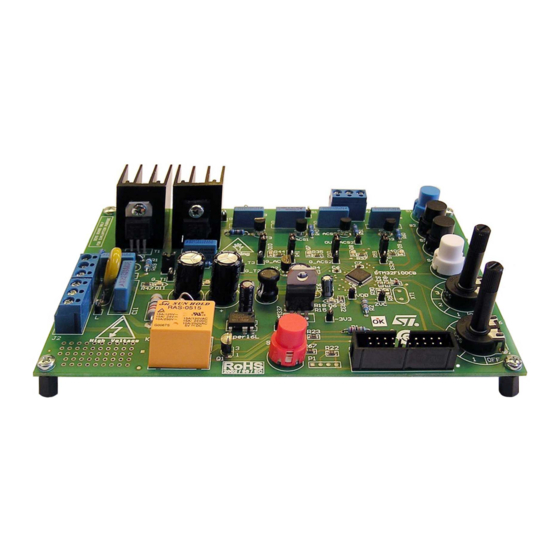
STEVAL-IHT005V2 - 3.3 V control of ACS
/Triac with STM32™
Introduction
The STEVAL-IHT005V2 demonstration board is designed for the home appliance market,
with a focus on the demonstration of a robust solution with a 3.3 V supplied 32-bit MCU.
Targeted applications are mid-end and high-end washing machines, dishwashers and
®
dryers with different kinds of ACS
/Triacs.
The demonstration board is based on the recently introduced 48-pin, 32-bit
STM32F100C4T6B MCU running at 24 MHz (RC user-trimmable internal RC clock),
featuring 16 kBytes of Flash memory, 12-bit A/D converter, 5 timers, communication
interfaces, and 4 kBytes of SRAM.
®
The power supply circuitry is based on the VIPer
16L, an offline converter with an 800 V
avalanche rugged power section, operating at 60 kHz. The power supply provides negative
6 V in buck-boost topology.
The STEVAL-IHT005V2 can control 2 high power loads up to 2830 W thanks to the T1635H,
a 16 A, 600 V high temperature Triac and up to 2050 W thanks to the ACST1635-8FP
a 16 A, 800 V high temperature overvoltage protected ACST device. The high power load
control is based on phase angle control. In order to limit the inrush current and possible
current peaks, the demonstration board features a soft-start routine and a smooth power
change function for the high power loads.
The STEVAL-IHT005V2 can also control 4 low power loads up to 100 W thanks to
3 ACS108-8S, 0.8 A, 800 V overvoltage protected ACS devices and a Z0109, 1 A standard
4 quadrant 600 V Triac.
The demonstration board passed the precompliance tests for EMC directives
IEC 61000-4-4 (burst up to 8 kV) and IEC 61000-4-5 (surge up to 2 kV).
When put in standby mode, the STEVAL-IHT005V2 has an overall standby power
consumption below 500 mW at 264 V/50 Hz.
Figure 1. STEVAL-IHT005V2
October 2013
DocID024503 Rev 1
1/27
www.st.com
Advertisement
Table of Contents

Related Manuals for STMicroelectronics STEVAL-IHT005V2


Summary of Contents for STMicroelectronics STEVAL-IHT005V2
- Page 1 60 kHz. The power supply provides negative 6 V in buck-boost topology. The STEVAL-IHT005V2 can control 2 high power loads up to 2830 W thanks to the T1635H, a 16 A, 600 V high temperature Triac and up to 2050 W thanks to the ACST1635-8FP a 16 A, 800 V high temperature overvoltage protected ACST device.
-
Page 2: Table Of Contents
Connection diagram ......... . 7 How to operate the STEVAL-IHT005V2 ......7 MCU programming . - Page 3 Immunity to relay switching ........17 Appendix A STEVAL-IHT005V2 schematic ......19 Schematic .
-
Page 4: Board Features And Objectives
The board is designed for promotion of a complete solution for home appliance applications based on STMicroelectronics™ components. Special emphasis is placed on demonstration of the robust full 3.3 V solution. Robustness is demonstrated on 4 kV level in class A during IEC-61000-4-4 (burst) test. -
Page 5: Board Features
UM1631 Board features and objectives Board features The board key features and performances are Complete solution for -3.3 V control Input voltage range: 90-265 VAC 50/60 Hz Negative 6 V/3.3 V VDC auxiliary power supply based on the VIPer16L in buck-boost topology ... -
Page 6: Safety Instructions
Installation Installation instructions for the STEVAL-IHT005V2 demonstration board must be taken from the present user manual and strictly observed. The components must be protected against excessive strain. In particular, no components are to be bent, or isolating distances altered during transportation, handling or use. -
Page 7: Getting Started
Figure 2. Board connector Note: Connect loads and voltage probes before applying line voltage. How to operate the STEVAL-IHT005V2 Line voltage must be connected in position as described in Figure 2. The demonstration board can be operated with or without the load. - Page 8 Getting started UM1631 that the gate control signal is applied. If the load (example motor) is running and the LED lights up, it indicates the MCU properly controls the Triac(s). Blue, black and white buttons control the 3x ACS108 and Z01 in ON/OFF mode with zero voltage synchronization.
-
Page 9: Mcu Programming
MCU programming Once the demonstration board has the mains cable and load cable correctly connected, it can be powered on. The STEVAL-IHT005V2 demonstration board goes to wait-for-signal mode immediately after powering it on. A JTAG connector for MCU programming is used when software modifications are necessary. -
Page 10: Functional Description
Functional description UM1631 Functional description Two different types of ACS/Triac control are implemented. Phase angle control and full wave control. The gate control signal is synchronized with zero voltage crossing signal (ZVC). The MCU operation is also synchronized with ZVC signal. ZVC signal is sent directly to the MCU input pin that is set as external interrupt. - Page 11 UM1631 Functional description Figure 5. Full wave control description Full wave pulse control is based on sending gate control pulse immediately after ZVC signal. Gate control pulse length is defined by the software. Refer to Table 2 for default gate current pulse duration for all AC switches. Duration of each pulse is set separately for 50 Hz and 60 Hz mains.
-
Page 12: Power Supply Consumption
Power supply consumption UM1631 Power supply consumption Max. output current and standby consumption Non-isolated SMPS based on the VIPer16 in buck-boost topology is designed to provide output voltage of -6 V. Maximum output current is 120 mA. -3.3 V voltage supply necessary to supply MCU consists of linear regulator LM337. -
Page 13: Pulsed Gate Control And Average Gate Current Consumption
UM1631 Power supply consumption ACS devices have lower V variation with load current than Triacs and that is why they are more suitable for 3.3 V applications as the gate current variation is lower. Refer to the AN2986 application note for further details and for gate resistor calculation. Pulsed gate control and average gate current consumption Table 3 gives the initial gate current pulse widths for each AC switch, and the maximum... -
Page 14: Board Immunity Performances
Board immunity performances UM1631 Board immunity performances Hardware and software features to increase immunity Software features Software features to improve board immunity are Filtering procedure for button and potentiometer control Software watchdog Hardware features to improve board immunity are ... -
Page 15: Burst Tests Results
AC switches, it was necessary to add two other X2 capacitors: 100 nF and 220 nF, as each of them influenced a different type of coupling. These two capacitors are not included on the STEVAL-IHT005V2 board as only Z0109 was below 4 kV level. -
Page 16: Noise Suppressor Influence
Board immunity performances UM1631 Table 5. IEC-61000-4-4 results with input filter modification STEVAL-IHT005V2 2 kV 4 kV 6 kV 8 kV 254 VAC - 50 Hz Standby ON + level 3 (5.2 ms) Standby ON + level 3 (5.2 ms) -
Page 17: Gate Filtering Circuit Influence
UM1631 Board immunity performances 6.3.5 Gate filtering circuit influence The gate filtering circuit has an influence mainly on sensitive devices. When the gate filtering circuit is removed, the immunity of Z01 decreases to 2 kV and immunity of ACS108 is decreased to 4 kV. Gate filtering circuit is not mandatory to pass IEC-61000-4-4 tests for ACS108. - Page 18 Board immunity performances UM1631 Figure 8. dV/dt behavior during turn-on 18/27 DocID024503 Rev 1...
-
Page 19: Appendix A Steval-Iht005V2 Schematic
UM1631 STEVAL-IHT005V2 schematic Appendix A STEVAL-IHT005V2 schematic Schematic Figure 9. STEVAL-IHT005V2 schematic VSS_ 1 23 PB11 PB10 21 BOOT0 DocID024503 Rev 1 19/27... -
Page 20: Demonstration Board Layout
STEVAL-IHT005V2 schematic UM1631 Demonstration board layout Figure 10. STEVAL-IHT005V2 - top layer Figure 11. STEVAL-IHT005V2 - bottom layer 20/27 DocID024503 Rev 1... -
Page 21: Test Point Lists
UM1631 STEVAL-IHT005V2 schematic Test point lists Table 7. Test points definition Name Definition G_T1 Control signal of T1 (T1635H) “Zero Voltage Crossing” signal -6 V Reference of SMPS output voltage N_VDD Neutral reference and V -3.3 V Reference for MCU power supply... -
Page 22: Assumptions For Calculation
2 x 15 ACST16 30.4 2 x 15 112.2 2 x 56 ACS108 107.8 2 x 51 112.2 2 x 56 Z0109 107.8 2 x 51 In the STEVAL-IHT005V2 demonstration board tolerance resistors of 1% are used. 22/27 DocID024503 Rev 1... -
Page 23: Bill Of Material
UM1631 STEVAL-IHT005V2 schematic Bill of material Table 9. Bill of material Quan- Designator Value Description Vendor Order code tity Capacitor Header, 4-pin C17, C18 Capacitor R6, R7 Resistor R9, R30 Resistor X2 47 nF/305 V Capacitor EPCOS B32922C3473K000 C2, C12, C14,... - Page 24 STEVAL-IHT005V2 schematic UM1631 Table 9. Bill of material (continued) Quan- Designator Value Description Vendor Order code tity 22 - 5% 2 W Resistor 100 0.6 W Resistor P-DT6BL Button S2, S3 P-DT6SW Button P-DT6WS Button P-DT6RT Button Crystal oscillator (HC49/U 8 MHz) 4.7 F/450 V...
- Page 25 UM1631 STEVAL-IHT005V2 schematic Table 9. Bill of material (continued) Quan- Designator Value Description Vendor Order code tity R20, R22, R53, R54, R55, R56, 4.7 k0805 SMD Resistor R24, R25, R29, 56 0805 SMD R38, R39, R48, Resistor R49, R57, R58...
-
Page 26: Revision History
Revision history UM1631 Revision history Table 10. Document revision history Date Revision Changes 01-Oct-2013 Initial release. 26/27 DocID024503 Rev 1... - Page 27 Please Read Carefully: Information in this document is provided solely in connection with ST products. STMicroelectronics NV and its subsidiaries (“ST”) reserve the right to make changes, corrections, modifications or improvements, to this document, and the products and services described herein at any time, without notice.
Need help?
Do you have a question about the STEVAL-IHT005V2 and is the answer not in the manual?
Questions and answers