Table of Contents
Advertisement
Quick Links
Advertisement
Table of Contents

Related Manuals for Aaeon MIX-H310D1


Summary of Contents for Aaeon MIX-H310D1
- Page 1 MIX-H310D1...
- Page 2 E15384 First Edition March 2019 Copyright Notice This document is copyrighted, 2019. All rights are reserved. The original manufacturer reserves the right to make improvements to the products described in this manual at any time without notice. No part of this manual may be reproduced, copied, translated, or transmitted in any form or by any means without the prior written permission of the original manufacturer.
-
Page 3: Table Of Contents
Contents Chapter 1 Product overview Package contents ................. 1-1 Features ..................1-1 1.3 Specifications ................1-2 Chapter 2 Motherboard information Before you proceed ..............2-1 Motherboard layout ..............2-2 Screw size ..................2-4 2.3.1 Component side .............. 2-4 2.3.2 Solder side ..............2-5 Central Processing Unit (CPU) ........... - Page 4 3.3.6 SIO Configuration ............3-7 3.3.7 PCH-FW Configuration ........... 3-8 3.3.8 Power Management ............3-8 3.3.9 Digital IO Port Configuration ........... 3-9 Chipset menu ................3-9 3.4.1 System Agent (SA) Configuration ........3-9 3.4.2 PCH-IO Configuration ........... 3-10 Security menu ................3-10 3.5.1 Administrator Password ..........3-10 3.5.2 User Password .............. 3-10 Boot menu ..................
-
Page 5: Chapter 1 Product Overview
Chapter 1 Product overview Package contents Check your industrial motherboard package for the following items. 1 x Industrial Motherboard 1 x SATA cable 1 x SATA power cable 1 x I/O Shield 1 x Support CD NOTE: If any of the above items is damaged or missing, contact your distributor or sales representative immediately. -
Page 6: Specifications
LVDS Up to 1920 x 1200 @60 Hz, Dual Channel 18/24 bit colay with eDP UP to 4096 x 2340 @ 60Hz (could only use 1 function at a time since only support 1 x inverter) Backlight Control Voltage / PWM (continued on the next page) MIX-H310D1... - Page 7 Storage 2 x SATA 6.0Gb/s 4 pin SATA power (5V, 12V @1A) 4 x USB 3.1 Gen 1 ports (4 ports in Rear IO) 5 x USB 2.0 ports (5 ports for internal pin header) Display I/O 1x LVDS, 1x eDP, 2x HDMI / DP (HDMI and DP colay, default: 1x HDMI, 1x DP) Audio I/O Mic-in, Line-out, AAFP at internal connector for 2 additional chan-...
- Page 8 1 x Buzzer on board (Pin Header) 1 x AT/ATX mode select jumper 1 x clear CMOS jumper OTHERS OS Support Windows ® Accessories 1 x SATA cable 1 x SATA power cable I/O Shield Support DVD NOTE: Specifications are subject to change without notice. MIX-H310D1...
-
Page 9: Chapter 2 Motherboard Information
Chapter 2 Motherboard information Before you proceed Take note of the following precautions before you install motherboard components or change any motherboard settings. CAUTION! • Unplug the power cord from the wall socket before touching any component. • Before handling components, use a grounded wrist strap or touch a safely grounded object or a metal object, such as the power supply case, to avoid damaging them due to static electricity. -
Page 10: Motherboard Layout
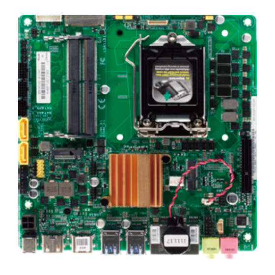
DDR4 SO-DIMM_A1 (64bit, 240-pin module) USB56 USB78 USB3_12 Place this side towards the rear of the chassis Intel ® USB3_34 H310 8111H LAN1 LGA1151 SATA_PWR 8111H LAN2 M.2_TYPE_E1 BATTERY_H LINE-OUT RT3607CE AAFP AMP_CON 2230 USB9 MIC-IN PCIEX4_1 MIX-H310D1 23 22 MIX-H310D1... - Page 11 Connectors/Jumpers/Slots Page EATX power connector (4-pin EATX_PWR2) 2-25 CPU and chassis fan connectors (4-pin CPU_FAN1, 4-pin CHA_FAN1) 2-18 Serial ATA 6.0Gb/s connectors (7-pin SATA6G_1/2) 2-21 DDR4 SO-DIMM slots 2-11 Serial port connectors (10-pin COM1, COM2) 2-24 Digital I/O connector (10-pin DIO) 2-19 COM1 RS422/RS485 terminator (2-pin J1/J2/J3/J4) 2-15...
-
Page 12: Screw Size
Screw size 2.3.1 Component side MIX-H310D1... -
Page 13: Solder Side
2.3.2 Solder side Chapter 2: Motherboard information... -
Page 14: Central Processing Unit (Cpu)
/ Celeron ® ® ® processors. MIX-H310D1 MIX-H310D1 CPU socket LGA1151 IMPORTANT: Unplug all power cables before installing the CPU. CAUTION! • Upon purchase of the motherboard, ensure that the PnP cap is on the socket and the socket contacts are not bent. Contact your retailer immediately if the PnP cap is missing, or if you see any damage to the PnP cap/socket contacts/motherboard components. -
Page 15: Installing The Cpu
2.4.1 Installing the CPU CAUTION! LGA1156 CPU is not compatible with the LGA1151 socket. DO NOT install an LGA1156 CPU on the LGA1151 socket. Chapter 2: Motherboard information... - Page 16 MIX-H310D1...
-
Page 17: Cpu Heatsink And Fan Assembly Installation
2.4.2 CPU heatsink and fan assembly installation CAUTION! Apply the Thermal Interface Material to the CPU heatsink and CPU before you install the heatsink and fan if necessary. To install the CPU heatsink and fan assembly Chapter 2: Motherboard information... - Page 18 To uninstall the CPU heatsink and fan assembly MIX-H310D1 2-10...
-
Page 19: System Memory
This motherboard comes with two Double Data Rate 4 (DDR4) Small Outline Dual Inline Memory Module (SO-DIMM) sockets. The figure below illustrates the location of the DDR4 SO-DIMM sockets: Channel Sockets SO-DIMM_B1 Channel A SO-DIMM_A1 SO-DIMM_A1 Channel B SO-DIMM_B1 MIX-H310D1 MIX-H310D1 240-pin DDR4 SO-DIMM sockets 2.5.1 Installing a DIMM To install a DIMM To remove a DIMM Chapter 2: Motherboard information 2-11... -
Page 20: Jumpers
CMOS, which include system setup information such as system passwords. MIX-H310D1 MIX-H310D1 Clear RTC RAM To erase the RTC RAM: Turn OFF the computer and unplug the power cord. Move the jumper cap from pins 1-2 (default) to pins 2-3. Keep the cap on pins 2-3 for about 5~10 seconds, then move the cap back to pins 1-2. - Page 21 (Default) MIX-H310D1 MIX-H310D1 COM1 Ring/+5V/+12V Selection Setting Pins +12V Ring (Default) LVDS panel voltage selection (3-pin LJ1) (Default) MIX-H310D1 MIX-H310D1 LVDS Panel Voltage Selection Pins +3.3V (Default) Inverter voltage selection (3-pin LJ2) +12V (Default) MIX-H310D1 MIX-H310D1 Inverter Voltage Selection Pins +12V (Default)
- Page 22 Inverter Backlight Control mode selection (3-pin LJ3) DC CTL PWM CTL (Default) MIX-H310D1 MIX-H310D1 Mode Selection for Back Light Control of Inverter Pins DC Voltage Control PWM Control (Default) AT/ATX Mode selection (2-pin ATX_AT) ATX_AT ATX mode AT mode (Default)
- Page 23 COM1 operating mode selection jumpers (2-pin J1/J2/J3/J4) COM1_J1~4 RS232 (Default) RS485/RS422 with terminator MIX-H310D1 MIX-H310D1 COM1 RS422/RS485 Terminator (J1/J2/J3/J4) Setting Pins Open jumpers J1, J2, J3 and J4 1-2 RS232 (Default) Short-circuit jumpers J1, J2, J3 and J4 RS485/RS422 with terminator...
-
Page 24: Connectors
LED indications. LAN port LED indications Speed Activity Link ACT/LINK LED SPEED LED Status Description Status Description No link 10 Mbps connection GREEN Linked ORANGE 100 Mbps connection LAN port BLINKING Data activity GREEN 1 Gbps connection MIX-H310D1 2-16... -
Page 25: Internal Connectors
Internal connectors SATA power connector (4-pin SATA_PWR) This connector is for the SATA power cable. The power cable plug is designed to fit this connector in only one orientation. Find the proper orientation and push down firmly until the connector completely fit. SATA_PWR +12V MIX-H310D1 MIX-H310D1 SATA POWER connector Audio amplfier connector (4-pin AMP_CON) This connector is for an internal stereo amplifier speakers support (2W/4 via WtoB header). AMP_CON PIN 1 MIX-H310D1 MIX-H310D1 Audio Stere. - Page 26 CHA_FAN1 CPU_FAN1 MIX-H310D1 MIX-H310D1 Fan connectors CAUTION: Do not forget to connect the fan cables to the fan connectors. Insufficient air flow inside the system may damage the motherboard components. These are not jumpers! Do not place jumper caps on the fan...
- Page 27 Intrudor No Intrudor PIN1 MIX-H310D1 MIX-H310D1 Chassis intrusion connector Digital I/0 connector (10-pin DIO) This connector includes 8 I/O lines (In/Out programmable). All of the Digital I/O lines are programmable and each I/O pin can be individually programmed to support various devices.
- Page 28 PWR BTN PIN 1 +HDD_LED RESET MIX-H310D1 MIX-H310D1 System panel connector • System power LED (2-pin +PWR_LED) This 2-pin connector is for the system power LED. Connect the chassis power LED cable to this connector. The system power LED lights up when you turn on the system power, and blinks when the system is in sleep mode.
- Page 29 These connector connects to Serial ATA 6.0 Gb/s hard disk drives or an optical drive via Serial ATA 6.0 Gb/s signal cables. MIX-H310D1 MIX-H310D1 SATA 6.0Gb/s connectors NOTE: You must install Windows 7 or later version before using Serial ATA ®...
- Page 30 This connector is for an internal embedded DisplayPort connection. EDP(Bottom) PIN 1 +V_PANEL eDP_TXN3_C eDP_TXP3_C eDP_TXN2_C eDP_HPD_RRR eDP_TXP2_C eDP_TXN1_C eDP_TXP1_C BKLTEN_R eDP_TXN0_C BKLTCTL_R eDP_TXP0_C eDP_AUXP_C +BLVCC eDP_AUXN_C +BLVCC +BLVCC +V_PANEL +BLVCC +V_PANEL +V_PANEL MIX-H310D1 MIX-H310D1 Embedded Display Port MIX-H310D1 2-22...
- Page 31 (NC) (NC) SPI_MISO SPI_MOSI SPI_CS# SPI_CLK +3V_SPI PIN 1 MIX-H310D1 MIX-H310D1 BIOS Programmable connector NOTE: The flash BIOS cable is purchased separately. 14. Battery connector (2-pin BATTERY_H) This connector is for the lithium CMOS battery. BATTERY_H +BAT PIN 1 MIX-H310D1 MIX-H310D1 Battery Holder connector 15. Backlight inverter power connector (5-pin INV) Connect the backlight inverter power cable to this connector.
- Page 32 These connectors are for serial (COM) ports. Connect the serial port cables to these connectors, then install the module to a slot opening at the back of the system chassis. COM1 COM2 PIN 1 PIN 1 MIX-H310D1 MIX-H310D1 Serial port connectors Signal Signal DCD (422TXD-/485DATA- RXD (422RXD+ /485DATA+) TXD (422TXD+) DTR (422RXD-) RI/+12V/+5V N.C.
- Page 33 EATX_PWR2 PIN 1 MIX-H310D1 MIX-H310D1 1 x 4 PIN (2x2) internal power connector 18. Front panel audio connector (10-1 pin AAFP) This connector is for a chassis-mounted front panel audio I/O module that supports HD Audio standard. Connect one end of the front panel audio I/O module cable to this connector.
-
Page 34: Power Supply Considerations
• System power requirements will depend on actual system configurations chosen by the integrator, as well as end user expansion preferences. It is the system integrator’s responsibility to ensure an appropriate power budget for the system configuration is properly assessed based on the system-level components chosen. • Considering the power conversion efficiency between Vin (+12V), the Vout (+12V) output voltage is set around 11.6V. MIX-H310D1 2-26... -
Page 35: Chapter 3 Bios Setup
Chapter 3 BIOS setup BIOS setup program Use the BIOS Setup program to update the BIOS or configure its parameters. The BIOS screens include navigation keys and brief online help to guide you in using the BIOS Setup program. Entering BIOS Setup at startup To enter BIOS Setup at startup: Press <Delete> during the Power-On Self Test (POST). If you do not press <Delete>, POST continues with its routine. -
Page 36: Bios Menu Screen
Case Open Warning [Disabled] Allows you to enable or disable case open warning function. Configuration options: [Disabled] [Enabled] [Clear] 3.3.1 CPU Configuration The items in this menu show CPU-related information the BIOS automatically detects. The items shown in the submenu may be different depending on the type of CPU installed. MIX-H310D1... -
Page 37: Trusted Computing
Intel (VMX) Virtualization Technology [Enabled] [Enabled] Allows a hardware platform to run multiple operating systems separately and simultaneously, enabling one system to virtually function as several systems. [Disabled] Disables this function. 3.3.2 Trusted Computing Security Device Support [Enable] Allows you to enable or disable BIOS support for security devices. Configuration options: [Disable] [Enable] SHA-1 PCR Bank [Enabled] Allows you to enable or disable SHA-1 PCR Bank. Configuration options: [Disabled] [Enabled]... -
Page 38: Sata Configuration
Port 2 [Enabled] These items allow you to enable/disable the SATA port(s). Configuration options: [Disabled] [Enabled] 3.3.4 USB Configuration The USB Devices item lists auto-detected values. If no USB device is detected, the item shows None. Legacy USB Support [Enabled] [Enabled] Enables the support for USB devices on legacy operating systems (OS). MIX-H310D1... -
Page 39: Hardware Monitor
[Disabled] USB devices are only available when running BIOS Setup. [Auto] Allows the system to detect the presence of USB devices at startup. If detected, the USB controller legacy mode is enabled. If no USB device is detected, the legacy USB support is disabled. - Page 40 Fan Out Step Down Time [xx] Determines the time that Fan Out takes to decrease its value by one step. The units are intervals of 0.1 second. The values range from 0~255. System Smart Fan Control [Enabled] Allows you to enable or disable System Smart Fan Control. Configuration options: [Enabled] [Disabled] MIX-H310D1...
- Page 41 Fan Control Mode [SMART FAN IV Mode] Select fan control mode. Configuration options: [Manual Mode] [Thermal Cruise Mode] [SMART FAN IV Mode] The following 6 items appear only when you set Fan Control Mode to [Smart FAN IV Mode]. Temperature source [SYSTIN] Temperature 1~4 [xx] Input temperature setting. The values range from 0~255. Fan PWM 1~4 [xx] Input amount of Fan PWM 4 for Smart Fan IV Mode.
-
Page 42: Sio Configuration
Use this device [Enabled] Allows you to enable or disable this logical device. Configuration options: [Enabled] [Disabled] The following two items appear only when you set Use this device to [Enabled]. Possible [Use Automatic Settings] Allows you to select an optimal setting for Super I/O devices. Configuration options: [Use Automatic Settings] [IO=3F8h; IRQ=4;] [IO=3E8h; IRQ=7] Mode [RS-232] Allows you to select the Serial Port mode. Configuration options: [RS-232] [RS-422] [RS-485] MIX-H310D1... -
Page 43: Pch-Fw Configuration
[*Active*] Serial Port 2 Use this device [Enabled] Allows you to enable or disable this logical device. Configuration options: [Enabled] [Disabled] Possible [Use Automatic Settings] This item appears only when you set Use this device to [Enabled] and allows you to select an optimal setting for Super I/O devices. Configuration options: [Use Automatic Settings] [IO=3E8h; IRQ=7] [IO=3F8h; IRQ=4;] 3.3.7 PCH-FW Configuration The items listed in this screen display firmware related information. Firmware Update Configuration Me FW Image Re-Flash [Disabled] Allows you to enable or disable Me firmware Image Re-Flash function. -
Page 44: Digital Io Port Configuration
Specify the number of minutes added to the current time before waking up system. Input value range: [1~5] 3.3.9 Digital IO Port Configuration The items listed in this screen configure Digital IO settings. DI0 Port1~DI0 Port4 [Output] Configuration options: [Input] [Output] The following item appears only when you set DI0 Port1/2/3/4 to [Output]. Output Level [High] Configuration options: [High] [Low] DI0 Port5~DI0 Port8 [Input] Configuration options: [Input] [Output] MIX-H310D1 3-10... -
Page 45: Chipset Menu
Chipset menu The Chipset menu items allow you to change the settings for the chipset. 3.4.1 System Agent (SA) Configuration Primary Display [Auto] Allows you to decide which graphics controller to use as the primary boot device. Configuration options: [Auto] [IGFX] [PEG] Primary IGFX Boot Display [VBIOS Default] Select the video device which will be activated during POST. -
Page 46: Security Menu
To change a user password: Select the User Password item and press <Enter>. From the Enter Current Password box, key in the current password, then press <Enter>. From the Create New Password box, key in a new password, then press <Enter>. Confirm the password when prompted. MIX-H310D1 3-12... -
Page 47: Boot Menu
To clear the user password, follow the same steps as in changing a user assword, but press <Enter> when prompted to create/confirm the password. After you clear the password, the User Password item on top of the screen shows Not Installed. Boot menu The Boot menu items allow you to change the system boot options. Boot Configuration Quiet Boot [Enabled] This item enables/disables Quiet Boot. Configuration options: [Disabled] [Enabled... -
Page 48: Save & Exit Menu
Select Yes to discard changes and exit. Save Options Save or discard changes to current configuration. Restore Defaults Save or restore User Defaults to all setup options. Save as User Defaults This item saves current configuration as User Default. Restore User Defaults This option restores User Defaults to all setup options. MIX-H310D1 3-14... -
Page 49: Appendix
Check local regulations for disposal of electronic products. DO NOT throw the mercury-containing button cell battery in municipal waste. This symbol of the crossed out wheeled bin indicates that the battery should not be placed in municipal waste. MIX-H310D1... - Page 50 印 刷 電 路 板 及 其 × ○ ○ ○ ○ ○ 電子組件 外 部 信 號 連 接 頭 × ○ ○ ○ ○ ○ 及線材 ○: 表示該有毒有害物質在該部件所有均質材料中的含量均在 SJ/T 11363- 2006 標准規定的限量要求以下。 ×: 表示該有毒有害物質至少在該部件的某一均質材料中的含量超出 SJ/T 11363-2006 標准規定的限量要求,然該部件仍符合歐盟指令 2002/95/ EC 的規范。 備註:此產品所標示之環保使用期限,係指在一般正常使用狀況下。 MIX-H310D1...
Need help?
Do you have a question about the MIX-H310D1 and is the answer not in the manual?
Questions and answers