Table of Contents
Advertisement
Quick Links
Advertisement
Table of Contents

Related Manuals for Aaeon MIX-KLUW1


Summary of Contents for Aaeon MIX-KLUW1
- Page 1 MIX-KLUW1...
- Page 2 E14730 First Edition September 2018 Copyright Notice This document is copyrighted, 2018. All rights are reserved. The original manufacturer reserves the right to make improvements to the products described in this manual at any time without notice. No part of this manual may be reproduced, copied, translated, or transmitted in any form or by any means without the prior written permission of the original manufacturer.
-
Page 3: Table Of Contents
Contents Chapter 1: Product overview Package contents ................. 1-1 Features ..................1-1 1.3 Specifications ................1-2 Chapter 2: Motherboard information Before you proceed ..............2-1 Motherboard layout ..............2-1 Screw size ..................2-4 2.3.1 Component side .............. 2-4 2.3.2 Solder side ..............2-5 Central Processing Unit (CPU) ........... - Page 4 Security menu ................3-10 3.5.1 Administrator Password ..........3-10 3.5.2 User Password .............. 3-11 Boot menu .................. 3-11 3.6.1 Boot Configuration ............3-11 3.6.2 Boot Option Priorities ............ 3-11 Save & Exit menu ............... 3-12 Appendix Notices .......................A-1...
-
Page 5: Chapter 1: Product Overview
Chapter 1 Product overview Package contents Check your industrial motherboard package for the following items. 1 x Industrial Motherboard 1 x SATA 6.0Gb/s cable 1 x I/O Shield 1 x Support CD If any of the above items is damaged or missing, contact your distributor or sales representative immediately. -
Page 6: Specifications
HDMI 1.4 up to 4096 x 2340 @24Hz colay with VGA (default: VGA) LVDS Up to 1920 x 1200 @60Hz, Daul Channel 18/24 bit (via CH7511B) Up to 4096 x 2304 @ 60Hz Backlight Control Voltage / PWM (continued on the next page) MIX-KLUW1... - Page 7 Environment, Power, and ME Battery Lithium battery Power requirement 12~19V DC Operating F~131 F (0 C~55 C) @ 7100U/3965U with Heatsink temperature F~140 F (0 C~60 C) @ 7600U/7300U/7200U with Cooler Operating humidity 0%~90% relative humidity, non-condensing Certificate CE & FCC Class A Form factor Mini ITX Form Factor: 6.7”x 6.7”...
- Page 8 1 x AT/ATX mode select jumper 1 x Clear CMOS jumper Others OS support Windows 10 64-bit, Ubuntu 16.04.4 LTS ® Accessories 1 x SATA cable 1 x SATA power cable 1 x I/O shield 1 x Support DVD NOTE: Specifications are subject to change without notice. MIX-KLUW1...
-
Page 9: Chapter 2: Motherboard Information
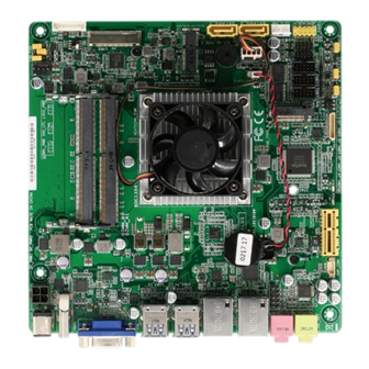
Chapter 2 Motherboard information Before you proceed Take note of the following precautions before you install motherboard components or change any motherboard settings. CAUTION! • Unplug the power cord from the wall socket before touching any component. • Before handling components, use a grounded wrist strap or touch a safely grounded object or a metal object, such as the power supply case, to avoid damaging them due to static electricity. • Hold components by the edges to avoid touching the ICs on them. • Whenever you uninstall any component, place it on a grounded antistatic pad or in the bag that came with the component. - Page 10 DDR4 SO-DIMM_ A1 (64bit, 260-pin module) Place this side towards the rear 2230 of the chassis USB3_12 Intel ® USB3_34 M2_TYPE_E SOC1356 128Mb BIOS LAN1 219LM SPI_1 MIX-KLUW1 211AT LAN2 BATTERY CPU_FAN MIC-IN AAFP COM1 COM2 Super 2280 2242 LINE-OUT COM1_J4/J3/J2/J1 PCIEX1 COM1_VSET CLRTC...
- Page 11 Connectors/Jumpers/Slots Page DCIN 12V AUX power connector (4-pin DC_PWR2) 2-13 DDR4 DIMM slots CPU and chassis fan connectors (4-pin CPU_FAN, 4-pin CHA_FAN) 2-14 Inverter voltage selection jumper (3-pin BKL_PWR) 2-11 Inverter backlight control mode selection jumper (3-pin INV_CTL) 2-11 LVDS panel voltage selection jumper (3-pin LVDS_PWR) 2-11 Backlight inverter power connector (8-pin INV) 2-18 LVDS connector (40-pin LVDS) 2-18 Intel processor ® 10. BIOS programmable connector (8-pin SPI_1) 2-13 11. M.2 M Key and M.2 E Key slots 2-17 12. SATA 6.0Gb/s connectors (7-pin SATA6G_1~2) 2-14 13. Battery connector (2-pin BATTERY) 2-20 14. SATA power connector (4-pin SATA_PWR) 2-19 15. System panel connector (10-1 pin F_PANEL) 2-15 16. USB 2.0 connectors (10-pin USB56, USB78) 2-15 17.
-
Page 12: Screw Size
Screw size 2.3.1 Component side MIX-KLUW1... -
Page 13: Solder Side
2.3.2 Solder side Chapter 2: Motherboard information... -
Page 14: Central Processing Unit (Cpu)
Central Processing Unit (CPU) This motherboard comes with an Intel 7th Generation 14nm KabyLake U ® FCBGA1356 processor. Intel ® SOC1356 MIX-KLUW1 MIX-KLUW1 CPU onboard IMPORTANT: Unplug all power cables before installing the CPU. CAUTION! • Upon purchase of the motherboard, ensure that the PnP cap is on the socket and the socket contacts are not bent. Contact your retailer immediately if the PnP cap is missing, or if you see any damage to the PnP cap/socket contacts/motherboard components. • Keep the cap after installing the motherboard. The manufacturer will process Return Merchandise Authorization (RMA) requests only if the motherboard comes with the cap on the socket. • The product warranty does not cover damage to the socket contacts resulting from incorrect CPU installation/removal, or misplacement/loss/ incorrect removal of the PnP cap. MIX-KLUW1... -
Page 15: System Memory
System memory This motherboard comes with two Double Data Rate 4 (DDR4) Small Outline Dual Inline Memory Modules (SO-DIMM) sockets. The figure illustrates the location of the DDR4 DIMM sockets: DIMM_B1 DIMM_A1 MIX-KLUW1 MIX-KLUW1 260-pin DDR4 SO-DIMM sockets NOTE: Use the DIMM_A1 slot when inserting only one SO-DIMM. Installing a DIMM To install a DIMM To remove a DIMM Chapter 2: Motherboard information... -
Page 16: Jumpers
Jumpers Clear RTC RAM (3-pin CLRTC1) This jumper allows you to clear the Real Time Clock (RTC) RAM in CMOS. You can clear the CMOS memory of system setup parameters by erasing the CMOS RTC RAM data. The onboard button cell battery powers the RAM data in CMOS, which include system setup information such as system passwords. MIX-KLUW1 MIX-KLUW1 Clear RTC RAM To erase the RTC RAM: 1. Turn OFF the computer and unplug the power cord. 2. Move the jumper cap from pins 1-2 (default) to pins 2-3. Keep the cap on pins 2-3 for about 5~10 seconds, then move the cap back to pins 1-2. 3. Plug the power cord and turn ON the computer. 4. Hold down the <Del> key during the boot process and enter BIOS setup to reenter data. CAUTION! Except when clearing the RTC RAM, never remove the cap on CLRTC jumper default position. Removing the cap will cause system boot failure! NOTES: • If the steps above do not help, remove the onboard battery and move the jumper again to clear the CMOS RTC RAM data. After clearing the CMOS, reinstall the battery. - Page 17 Setting Pins +12V Ring (Default) COM1 operating mode selection jumpers (2-pin COM1_J1, COM1_J2, COM1_J3, COM1_J4) COM1_J4/J3/J2/J1 RS232 (Default) RS485/RS422 MIX-KLUW1 with terminator MIX-KLUW1 COM1 operating mode selection jumpers Setting Pins RS232 Open jumpers J1, J2, J3 and J4 (Default) RS485/RS422 with terminator Short-circuit jumpers J1, J2, J3 and J4 Chapter 2: Motherboard information...
- Page 18 AT/ATX mode selection (3-pin AT_ATX) AT_ATX MIX-KLUW1 MIX-KLUW1 AT/ATX mode selection Pins ATX mode (Default) AT mode Chassis intrusion jumper (4-1 pin CHASSIS) This connector is for a chassis-mounted intrusion detection sensor or switch. Connect one end of the chassis intrusion sensor or switch cable to this connector. The chassis intrusion sensor or switch sends a high-level signal to this connector when a chassis component is removed or replaced. The signal is then generated as a chassis intrusion event. Move the jumper cap to pins 1-2 when you intend to use the chassis intrusion detection feature. CHASSIS MIX-KLUW1...
- Page 19 +12V (Default) MIX-KLUW1 MIX-KLUW1 Inverter voltage selection Setting Pins DC Voltage Control (Default) PWM Control Inverter backlight control mode selection (3-pin INV_CTL) INV_CTL DC mode PWM mode (Default) MIX-KLUW1 MIX-KLUW1 Inverter backlight control mode selection Setting Pins +12V +5V (Default) Chapter 2: Motherboard information 2-11...
-
Page 20: Connectors
Green Linked Orange 100 Mbps connection Green Data activity Green 1 Gbps connection LAN port Orange Ready to wake (Blinking up from S5 then steady) mode Microphone port (pink). This port connects to a microphone. Line Out port (lime). This port connects to a headphone or a speaker. MIX-KLUW1 2-12... -
Page 21: Internal Connectors
MIX-KLUW1 MIX-KLUW1 DCIN power connector Speaker out connector (4-pin AMP_CON) The 4-pin connector is for the chassis-mounted speaker. AMP_CON PIN 1 MIX-KLUW1 MIX-KLUW1 Audio stere. output with Amp connector The Speaker module is purchased separately. BIOS programmable connector (8-pin SPI_1) Use this connector to flash the BIOS ROM. SPI_1 (NC) (NC) SPI_MISO... - Page 22 MIX-KLUW1 Fan connectors CAUTION: Do not forget to connect the fan cables to the fan connectors. Insufficient air flow inside the system may damage the motherboard components. These are not jumpers! Do not place jumper caps on the fan connectors! SATA 6.0Gb/s connectors (7-pin SATA6G_1~2) These connectors connect to Serial ATA 6.0 Gb/s hard disk drives via Serial ATA 6.0 Gb/s signal cables. MIX-KLUW1 MIX-KLUW1 SATA 6.0Gb/s connectors IMPORTANT: When using hot-plug and NCQ, set the SATA Mode Selection item in the BIOS to [AHCI]. See section 3.3.3 SATA and RST Configuration for details. MIX-KLUW1 2-14...
- Page 23 System panel connectors (10-1 pin F_PANEL) This connector supports several chassis-mounted functions. (NC) RSTCON#_PANEL PWRBTN# PWR_LED- HDD_LED- PWR_LED+ HDD_LED+ MIX-KLUW1 PIN 1 MIX-KLUW1 System panel connector • System power LED (2-pin PWR_LED) This 2-pin connector is for the system power LED. Connect the chassis power LED cable to this connector. The system power LED lights up when you turn on the system power, and blinks when the system is in sleep mode. • Hard disk drive activity LED (2-pin HDD_LED) This 2-pin connector is for the HDD Activity LED. Connect the HDD Activity LED cable to this connector. The IDE LED lights up or flashes when data is read from or written to the HDD.
- Page 24 Serial port connectors (10-pin COM1~2) These connectors are for serial (COM) ports. Connect the serial port module cable to this connector, then install the module to a slot opening at the back of the system chassis. COM1 COM2 PIN 1 PIN 1 MIX-KLUW1 MIX-KLUW1 Serial port connectors NOTE: The COM module is purchased separately. Digital I/O connector (10-pin DIO) This connector includes 8 I/O lines (In/Out programmable). All of the Digital I/O lines are programmable and each I/O pin can be individually programmed to support various devices. MIX-KLUW1 PIN 1 MIX-KLUW1 Digital I/O connector NOTE: To configure the I/O pins in BIOS, go to the Advanced tab > Digital IO Port Configuration. See section 3.3.9 Digital IO Port Configuration for details.
- Page 25 2242 MIX-KLUW1 M.2 sockets NOTES: • The M.2 SSD module is purchased separately. • The M.2 E Key slot supports type 2230 PCIe Wi-Fi module. • The M.2 M Key slot supports type 2242/2280 SATA/PCIe storage devices. 11. Front panel audio connector (10-1 pin AAFP) This connector is for a chassis-mounted front panel audio I/O module that supports HD Audio audio standard. Connect one end of the front panel audio I/O module cable to this connector. AAFP PIN 1 MIX-KLUW1 MIX-KLUW1 Front panel audio connector IMPORTANT: We recommend that you connect a high-definition front panel audio module to this connector to avail of the motherboard’s high-definition audio capability. Chapter 2: Motherboard information 2-17...
- Page 26 LVDS0_D0- LVDS0_D0+ LVDS0_D1- LVDS0_D1+ LVDS0_D2- LVDS0_D2+ MIX-KLUW1 LVDS0_D3- LVDS0_D3+ PIN 1 MIX-KLUW1 LVDS connector 13. Backlight inverter power connector (8-pin INV) Connect the backlight inverter power cable to this connector. Decrement Backlight Brightness Increment Backlight Brightness Inverter VCC Inverter VCC Back Light Control MIX-KLUW1 Back Light Enable PIN1...
- Page 27 +V_PANEL +V_PANEL +V_PANEL +V_PANEL eDP_HPD_RRR BKLTEN_R BKLTCTL_R +BLVCC +BLVCC +BLVCC +BLVCC PIN 40 MIX-KLUW1 Embedded DisplayPort 15. SATA power connector (4-pin SATA_PWR) This connector is for the SATA power cable. The power cable plug is designed to fit this connector in only one orientation. Find the proper orientation and push down firmly until the connector completely fit. SATA_PWR +12V MIX-KLUW1 MIX-KLUW1 SATA power connector IMPORTANT: The SATA power connector supports 1A current to the maximum. Chapter 2: Motherboard information 2-19...
- Page 28 16. Battery connector (2-pin BATTERY) This connector is for the lithium CMOS battery. BATTERY MIX-KLUW1 +BAT PIN 1 MIX-KLUW1 Battery connector MIX-KLUW1 2-20...
-
Page 29: Chapter 3: Bios Setup
Chapter 3 BIOS setup BIOS setup Use the BIOS Setup to update the BIOS or configure settings. The BIOS screens include navigation keys and help to guide you in using the BIOS Setup program. Entering BIOS Setup at startup To enter BIOS Setup at startup: Press <Delete>... -
Page 30: Main Menu
Be cautious when changing the settings of the Advanced menu items. Incorrect field values can cause the system to malfunction. Case Open Warning [Disabled] Allows you to enable or disable case open warning function. Configuration options: [Disabled] [Enabled] [Clear] MIX-KLUW1... -
Page 31: Cpu Configuration
3.3.1 CPU Configuration The items in this menu show CPU-related information the BIOS automatically detects. The items shown in the submenu may be different depending on the type of CPU installed. Hyper-threading [Enabled] The Intel Hyper-Threading Technology allows a hyper-threading processor to appear as two logical processors to the operating system, allowing the operating system to schedule two threads or processes simultaneously. -
Page 32: Sata And Rst Configuration
[Disabled] [Enabled] Hot Plug [Disabled] These items allow you to enable/disable SATA Hot Plug Support. Configuration options: [Disabled] [Enabled] 3.3.4 AMT Configuration AMT BIOS Features [Enabled] When disabled, you are not able to access the MEBx setup. Configuration options: [Enabled] [Disabled] MIX-KLUW1... -
Page 33: Pch-Fw Configuration
3.3.5 PCH-FW Configuration Firmware Update Configuration Me FW Image Re-Flash [Disabled] This item allows you to enable or disable Me FW Image Re-Flash function. Configuration options: [Disabled] [Enabled] 3.3.6 SIO Configuration The items in this menu allow you to configure Super I/O settings. [*Active*] Serial Port 1 Use this device [Enabled] Allows you to enable or disable this logical device. -
Page 34: Nct6793D Hw Monitor
Sets the amount of time Fan Out takes to increase its value by one step. Input value range: [0~255] Fan Out Step Down Time [10] Sets the amount of time Fan Out takes to decrease its value by one step in intervals of 0.1 seconds. Input value range: [0~255] MIX-KLUW1... -
Page 35: Usb Configuration
The following item appears only when you set Fan Control Mode to [Manual Mode]. PWM/DC Voltage Output [255] Sets the voltage allocated for Fan Control. Input value range: [0~255] The following items appear only when you set Fan Control Mode to [Thermal Cruise Mode]. -
Page 36: Digital Io Port Configuration
Configuration options: [Disabled] [Enabled] . [Dynamic Time] The system will wake up at the current time plus a specified number of minutes. The following items appear when Fixed Time is enabled. Wake up day/hour/minute/second [0] Specify the values for day/hour/minute/second. MIX-KLUW1... -
Page 37: Chipset Menu
The following item appears when Wake System with Dynamic Time is enabled. Wake up minute increase [1] Specify the number of minutes added to the current time before waking up system. Input value range: [1~5] Resume from PME# [Enabled] Enables or disables resume from PCI PME#. Configuration options: [Disabled] [Enabled] Resume from PCIE/RI [Enabled] Enables or disables resume from PCIe devices or RING signals. -
Page 38: Pch-Io Configuration
To clear the administrator password, follow the same steps as in changing an administrator password, but press <Enter> when prompted to create/confirm the password. After you clear the password, the Administrator Password item on top of the screen shows Not Installed. MIX-KLUW1 3-10... -
Page 39: User Password
3.5.2 User Password If you have set a user password, you must enter the user password for accessing the system. The User Password item on top of the screen shows the default Not Installed. After you set a password, this item shows Installed. To set a user password: Select the User Password item and press <Enter>. -
Page 40: Save & Exit Menu
This option allows you to exit the Setup program without saving your changes. When you select this option or if you press <Esc>, a confirmation window appears. Select Yes to discard changes and reboot system. Restore Defaults Save or restore User Defaults to all setup options. MIX-KLUW1 3-12... -
Page 41: Appendix
Appendix Notices Federal Communications Commission Statement This device complies with Part 15 of the FCC Rules. Operation is subject to the following two conditions: • This device may not cause harmful interference. • This device must accept any interference received including interference that may cause undesired operation. - Page 42 ○ ○ ○ ○ 外部信號連接頭 × ○ ○ ○ ○ ○ 及線材 中央處理器與內 × ○ ○ ○ ○ ○ 存 本表格依據 SJ/T 11364 的規定編制。 ○: 表示該有害物質在該部件所有均質材料中的含量均在 GB/T 26572 規 定的限量要求以下。 ×: 表示該有害物質至少在該部件的某一均質材料中的含量超出 GB/T 26572 規定的限量要求,然該部件仍符合歐盟指令 2011/65/EU 的 規范。 備註:此產品所標示之環保使用期限,係指在一般正常使用狀況下。 MIX-KLUW1...
Need help?
Do you have a question about the MIX-KLUW1 and is the answer not in the manual?
Questions and answers