Table of Contents
Advertisement
Quick Links
Advertisement
Table of Contents

Related Manuals for Aaeon MAX-Q370C


Summary of Contents for Aaeon MAX-Q370C
- Page 1 MAX-Q370C...
- Page 2 E16810 First Edition June 2020 Copyright Notice This document is copyrighted, 2020. All rights are reserved. The original manufacturer reserves the right to make improvements to the products described in this manual at any time without notice. No part of this manual may be reproduced, copied, translated, or transmitted in any form or by any means without the prior written permission of the original manufacturer.
-
Page 3: Table Of Contents
Contents Chapter 1 Product overview Package contents ................. 1-1 Features ..................1-1 1.3 Specifications ................1-2 Chapter 2 Motherboard information Before you proceed ..............2-1 Motherboard layout ..............2-2 Screw size ..................2-4 2.3.1 Component side .............. 2-4 2.3.2 Solder side ..............2-5 Central Processing Unit (CPU) ........... - Page 4 3.3.3 SATA Configuration ............3-5 3.3.4 USB Configuration ............3-6 3.3.5 Hardware Monitor ............3-6 3.3.6 SIO Configuration ............3-12 3.3.7 AMT Configuration ............3-14 3.3.8 PCH-FW Configuration ..........3-14 3.3.9 Power Management ............3-14 3.3.10 Digital IO Port Configuration ......... 3-15 Chipset menu ................3-16 3.4.1 System Agent (SA) Configuration ......... 3-16 3.4.2 PCH-IO Configuration ...........
-
Page 5: Product Overview
Chapter 1 Product overview Package contents Check your industrial motherboard package for the following items. 1 x Industrial Motherboard 1 x SATA Cable 1 x I/O Shield 1 x COM port cable If any of the above items is damaged or missing, contact your distributor or sales representative immediately. -
Page 6: Specifications
9.6” x 9.6” (244mm x 244mm) Gross weight 1.76 lb (0.8 Kg) Operating 32~131°F (0~55°C) temperature Storage temperature -40°F ~185°F (-40°C ~85°C) Operating humidity 0%~90% relative humidity, non-condensing Power compliance Certificate CE/FCC Class A (continued on the next page) MAX-Q370C... - Page 7 DISPLAY Chipset Intel Graphics Media Accelerator ® DisplayPort Up to 4096 x 2160 @ 24 Hz / 3840 x 2160 @ 60 Hz, with Digital Audio HDMI Up to 4096 x 2160 @ 24 Hz / 2560 x 1600 @ 60 Hz with Digital Audio Up to 1920 x 1200 @ 60Hz (via IT6516B) Back I/O ports...
- Page 8 MAX-Q370C...
-
Page 9: Motherboard Information
Chapter 2 Motherboard information Before you proceed Take note of the following precautions before you install motherboard components or change any motherboard settings. CAUTION! • Unplug the power cord from the wall socket before touching any component. • Before handling components, use a grounded wrist strap or touch a safely grounded object or a metal object, such as the power supply case, to avoid damaging them due to static electricity. -
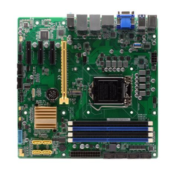
Page 10: Motherboard Layout
USB3_5678 USB3_9 1442K 1442K LGA1151 HDMI _DP1 Place this side towards the rear of the chassis LAN2_USB2_910 Intel ® PHY I219LM CHA_FAN1 LAN2_USB2_1112 MAX-Q370C 2242 AUDIO1 2280 M2_SSD_LED1 PCIEX16_1 BUZZER1 256Mb Intel ® BIOS I211AT SPI_1 PCIEX4_1 Intel ® Super... - Page 11 Connectors/Jumpers/Slots Page CPU and chassis fan headers (4-pin CPU_FAN1, 4-pin CHA_FAN1~2) 2-19 ATX power connectors (24-pin EATX_PWR1, 8-pin EATX_PWR2) 2-18 Intel LGA1151 CPU socket ® M.2 M-Key slot 2-23 DDR4 DIMM slots 2-10 COM Port headers (10-1 pin COM1~6) 2-22 BIOS programmable header (8-pin SPI_1) 2-18 SATA 6.0Gb/s ports (7-pin SATA6G_1~4)
-
Page 12: Screw Size
234.29 232.96 230.89 228.22 214.99 208.89 213.64 199.24 190.37 189.59 174.24 179.94 173.61 165.10 156.08 147.07 142.89 137.81 136.31 129.29 126.81 109.35 85.60 77.22 77.04 66.61 47.71 50.66 45.45 45.45 36.10 18.74 14.68 12.04 10.49 10.49 7.06 0.00 37.22 MAX-Q370C... -
Page 13: Solder Side
2.3.2 Solder side 237.49 237.49 195.23 165.10 165.10 164.31 151.99 144.81 126.81 108.81 89.69 89.31 89.31 51.69 33.02 10.16 0.00 Chapter 2: Motherboard information... -
Page 14: Central Processing Unit (Cpu)
Return Merchandise Authorization (RMA) requests only if the motherboard comes with the cap on the LGA1151 socket. • The product warranty does not cover damage to the socket contacts resulting from incorrect CPU installation/removal, or misplacement/loss/ incorrect removal of the PnP cap. MAX-Q370C... -
Page 15: Installing The Cpu
2.4.1 Installing the CPU CAUTION! Ensure that you install the correct CPU designed for LGA 1151 only. DO NOT install a CPU designed for LGA1155 and LGA1156 sockets on the LGA1151 socket. Chapter 2: Motherboard information... -
Page 16: Cpu Heatsink And Fan Assembly Installation
2.4.2 CPU heatsink and fan assembly installation CAUTION! Apply the Thermal Interface Material to the CPU heatsink and CPU before you install the heatsink and fan if necessary. To install the CPU heatsink and fan assembly MAX-Q370C... - Page 17 To uninstall the CPU heatsink and fan assembly Chapter 2: Motherboard information...
-
Page 18: System Memory
(DIMM) sockets. A DDR4 module is notched differently from a DDR, DDR2, or DDR3 module. DO NOT install a DDR, DDR2, or DDR3 memory module to the DDR4 slot. According to Intel CPU spec, DIMM voltage below 1.2 V is recommended to protect the ® CPU. 2.5.1 Installing a DIMM MAX-Q370C 2-10... - Page 19 To remove a DIMM Chapter 2: Motherboard information 2-11...
-
Page 20: Jumpers
CLRTC jumper default position. Removing the cap will cause system boot failure! NOTE: If the steps above do not help, remove the onboard battery and move the jumper again to clear the CMOS RTC RAM data. After clearing the CMOS, reinstall the battery. MAX-Q370C 2-12... - Page 21 COM1 RS422/RS485 terminator (2-pin J1~4) J1~4 RS232 RS485/RS422 with terminator (Default) AT/ATX Mode selection (2-pin ATX_AT) ATX_AT ATX mode AT mode (Default) Pins 1-2 (Default) ATX mode AT mode NOTE: Jumper setting of ATX_AT should be consistent with the setting of Power Mode in BIOS.
- Page 22 By default, the pin labeled “Chassis Signal” and “Ground” are shorted with a jumper cap. Remove the jumper caps only when you intend to use the chassis intrusion detection feature. CHASSIS COM1 Ring/+5V/+12V selector (6-pin COM1_V1) COM1_V1 +12V Ring (Default) Setting Pins +12V Ring (Default) MAX-Q370C 2-14...
- Page 23 Intel ME Jumper (3-pin DIS_ME) ® This jumper allows you to force the Intel Management Engine (ME) to boot ® from recovery mode when ME becomes corrupted. DIS_ME Enabled ME flash security(Default) Enabled ME flash security Disabled ME flash security Chapter 2: Motherboard information 2-15...
-
Page 24: Connectors
LED indications. LAN port LED indications Speed LED Activity Link ACT/LINK LED SPEED LED Status Description Status Description No link 10 Mbps connection ORANGE Linked ORANGE 100 Mbps connection BLINKING Data activity GREEN 1 Gbps connection LAN port MAX-Q370C 2-16... - Page 25 Line In port (light blue). This port connects to the tape, CD, DVD player, or other audio sources. Line Out port (lime). This port connects to a headphone or a speaker. In the 4.1, 5.1 and 7.1-channel configurations, the function of this port becomes Front Speaker Out. Microphone port (pink). This port connects to a microphone. Chapter 2: Motherboard information 2-17...
-
Page 26: Internal Connectors
We recommend that you use a PSU with higher power output when configuring a system with more power-consuming devices. The system may become unstable or may not boot up if the power is inadequate. BIOS programmable header (8-pin SPI_1) Use this header to flash the BIOS ROM. SPI_1 PIN 1 +3V_SPI SPI_CS# SPI_CLK SPI_MISO SPI_MOSI (NC) (NC) MAX-Q370C 2-18... - Page 27 CPU and chassis fan headers (4-pin CPU_FAN1, 4-pin CHA_FAN1~2) Connect the fan cables to the fan headers on the motherboard, ensuring that the black wire of each cable matches the ground pin of the header. CPU_FAN1 CHA_FAN1 CHA_FAN2 CAUTION: Do not forget to connect the fan cables to the fan headers. Insufficient air flow inside the system may damage the motherboard components.
- Page 28 Pressing the power switch for more than four seconds while the system is ON turns the system OFF. • Reset button (2-pin RESET) This 2-pin header is for the chassis-mounted reset button for system reboot without turning off the system power. MAX-Q370C 2-20...
- Page 29 SATA 6.0Gb/s connector (7-pin SATA6G_1~4) These connectors connect to Serial ATA 6.0 Gb/s hard disk drives via Serial ATA 6.0 Gb/s signal cables. SATA6G_1 SATA6G_2 SATA6G_3 SATA6G_4 RSATA_RXP RSATA_TXP RSATA_RXN RSATA_TXN RSATA_TXN RSATA_RXN RSATA_TXP RSATA_RXP NOTE: When using hot-plug and NCQ, set the SATA Mode Selection item in the BIOS to [AHCI].
- Page 30 The COM module is purchased separately. • COM1 also supports RS-232 / RS-422 / RS-485. See the table below and section 3.3.6 SIO Configuration for details. Signal Signal Signal DCD# (422TXD-/485DATA-) RXD (422TXD+/485DATA+) TXD (422RXD+) DTR# (422RXD-) DSR# RTS# CTS# RI/+5V/+12V N.C. MAX-Q370C 2-22...
- Page 31 M.2 M-key socket The M.2 M-key socket allows you to install an M.2 SSD module. M2_TYPE_M1 NOTES: • The M.2 module is purchased separately. • The M.2 M-key slot supports PCIe SSD (Ideal Speed:800MB/s) and 2280/2242 storage devices. 10. Digital I/O header (10-pin DIO1) This header includes 8 I/O lines (In/Out programmable).
- Page 32 The plugged USB 3.0 device will run on xHCI mode. 12. USB 3.2 Gen 1 port (USB3_9) This port allows you to connect a USB 3.2 Gen 1 cable for additional USB 3.2 Gen 1 front or rear panel ports. USB3_9 MAX-Q370C 2-24...
-
Page 33: Bios Setup
Chapter 3 BIOS setup BIOS setup program Use the BIOS Setup program to configure its parameters. The BIOS screens include navigation keys and brief online help to guide you in using the BIOS Setup program. Entering BIOS Setup at startup To enter BIOS Setup at startup: Press <Delete> during the Power-On Self Test (POST). If you do not press <Delete>, POST continues with its routine. -
Page 34: Bios Menu Screen
The Main menu provides you an overview of the basic system information, and allows you to set the system date, time, language, and security settings. 3.2.1 System Date [Day MM/DD/YYYY] Allows you to set the system date. 3.2.2 System Time [HH:MM:SS] Allows you to set the system time. MAX-Q370C... -
Page 35: Advanced Menu
Advanced menu The Advanced menu items allow you to change the settings for the CPU and other system devices. Be cautious when changing the settings of the Advanced menu items. Incorrect field values can cause the system to malfunction. Case Open Warning [Disabled] Allows you to enable or disable the case open detecting function. Configuration options: [Disable] [Enabled] [Clear] 3.3.1 CPU Configuration The items in this menu show CPU-related information the BIOS automatically... - Page 36 Compatible mode for Windows 8 / Windows ® ® [TCG_2] Newer TCG2 protocol and event format for Windows 10 or ® later. Physical Presence Spec Version [1.3] Allows you to select which TCG Physical Presence Interface Specification Version is supported by the OS. Configuration options: [1.2] [1.3] PH Randomization [Disabled] Allows you to select the PH Randomization. Configuration options: [Disabled] [Enabled] Device Select [Auto] Allows you to select the TPM device. Configuration options: [TPM1.2] [TPM2.0] [Auto] MAX-Q370C...
-
Page 37: Sata Configuration
3.3.3 SATA Configuration The BIOS automatically detects the presence of SATA devices. The Serial ATA Ports listed will display Empty if there are no Serial devices connected to the ports. SATA Controller(s) [Enabled] Configuration options: [Enabled] [Disabled]. The following items appear only when you set SATA Controller(s) to [Enabled]. SATA Mode Selection [AHCI] Allows you to set the SATA configuration. -
Page 38: Usb Configuration
The following item appears only when you set Fan Control Mode to [Manual Mode]. PWM/DC Voltage Output [255] Sets the voltage allocated for Fan Control. Input value range: [0~255] The following items appear only when you set Fan Control Mode to [Thermal Cruise Mode]. Target Temperature [50] Input value range: [0~127] MAX-Q370C... - Page 39 Tolerance of Temperature [0] Input value range: [0~7] Fan Out Start-Up Value [127] Input value range: [0~255] Fan Stop Duty [Down to 0] Selects fan stop duty mode. Configuration options: [Down to 0] [To Fan Out Stop Value] Fan Out Stop Value [100] The Fan Out value decreases to this value if the temperature reaches below the lowest temperature limit.
- Page 40 This item appears only when you set the previous item to [Manual Mode] and allows you to set the voltage allocated for Fan Control. Input value range: [0~255] The following items appear only when you set Fan Control Mode to [Thermal Cruise Mode]. MAX-Q370C...
- Page 41 Target Temperature [50] Input value range: [0~127] Tolerance of Temperature [0] Input value range: [0~7] Fan Out Start-Up Value [127] Input value range: [0~255] Fan Stop Duty [To Fan Out Stop Value] Selects fan stop duty mode. Configuration options: [Down to 0] [To Fan Out Stop Value] Fan Out Stop Value [100] The Fan Out value decreases to this value if the temperature reaches below the lowest temperature limit.
- Page 42 The following item appears only when you set Fan Control Mode to [Manual Mode]. PWM/DC Voltage Output [255] Sets the voltage allocated for Fan Control. Input value range: [0~255] The following items appear only when you set Fan Control Mode to [Thermal Cruise Mode]. MAX-Q370C 3-10...
- Page 43 Target Temperature [50] Input value range: [0~127] Tolerance of Temperature [0] Input value range: [0~7] Fan Out Start-Up Value [127] Input value range: [0~255] Fan Stop Duty [Down to 0] Selects fan stop duty mode. Configuration options: [Down to 0] [To Fan Out Stop Value] Fan Out Stop Value [100] The Fan Out value decreases to this value if the temperature reaches below the lowest temperature limit.
-
Page 44: Sio Configuration
[*Active*] Serial Port 1 Use this device [Enabled] Allows you to enable or disable this logical device. Configuration options: [Enabled] [Disabled] The following two items appear only when you set Use this device to [Enabled]. Possible [Use Automatic Settings] Allows you to select an optimal setting for Super I/O devices. Configuration options: [Use Automatic Settings] [IO=3F8h; IRQ=4;] [IO=3E8h; IRQ=7] MAX-Q370C 3-12... - Page 45 Mode [RS232] Allows you to select the Serial Port mode. Configuration options: [RS232] [RS422] [RS485] [*Active*] Serial Port 2 Use this device [Enabled] Allows you to enable or disable this logical device. Configuration options: [Enabled] [Disabled] Possible [Use Automatic Settings] This item appears only when you set Use this device to [Enabled] and allows you to select an optimal setting for Super I/O devices. Configuration options: [Use Automatic Settings] [IO=3E8h; IRQ=7] [IO=3F8h; IRQ=4;] [*Active*] Serial Port 3 Use this device [Enabled] Allows you to enable or disable this logical device. Configuration options:...
-
Page 46: Amt Configuration
AMT BIOS Features [Enabled] Allows you to enable or disable AMT BIOS features. Configuration options: [Disabled] [Enabled] 3.3.8 PCH-FW Configuration The items listed in this screen display firmware related information. Firmware Update Configuration Me FW Image Re-Flash [Disabled] Allows you to enable or disable Me firmware Image Re-Flash function. Configuration options: [Disabled] [Enabled] 3.3.9 Power Management Power Mode [ATX Type] Select power supply mode. Configuration options: [ATX Type] [AT Type] The following items appear when you set Power Mode to [ATX Type]. MAX-Q370C 3-14... -
Page 47: Digital Io Port Configuration
Restore AC Power Loss [Last State] [Last State] The system goes into either off or on state, whatever the system state was. [Always On] The system goes into on state after an AC power loss. [Always Off] The system goes into off state after an AC power loss. RI Wake Event [Disabled] Enable or disable system to wake up from RI#. Configuration options: [Enabled] [Disabled]... -
Page 48: Chipset Menu
[VGA] PCIEX16 Gen Speed [Auto] Allows you to select the PCI Express port speed. Configuration options: [Auto] [Gen1] [Gen2] [Gen 3] 3.4.2 PCH-IO Configuration HD Audio [Enabled] This item controls the detection of HD Audio devices. Configuration options: [Disabled] [Enabled] PCIEX4_1 Gen Speed [Auto] Configures the speed of PCI Express x4 slot. Configuration options: [Auto] [Gen1] [Gen2] [Gen3] PCIEX4_2 Gen Speed [Auto] Configures the speed of PCI Express x4 slot. Configuration options: [Auto] [Gen1] [Gen2] [Gen3] PCIEX4_3 Gen Speed [Auto] Configures the speed of PCI Express x4 slot. Configuration options: [Auto] [Gen1] [Gen2] [Gen3] MAX-Q370C 3-16... -
Page 49: Security Menu
Security menu The Security menu items allow you to change the system security settings. 3.5.1 Administrator Password If you have set an administrator password, we recommend that you enter the administrator password for accessing the system. Otherwise, you might be able to see or change only selected fields in the BIOS setup program. -
Page 50: Boot Menu
Hard Disk] [UEFI USB Key] [UEFI USB Hard Disk] [UEFI Network] [UEFI USB Lan] [UEFI CD/DVD] [UEFI USB CD/DVD] [UEFI USB Floppy] [Hard Disk] [ USB Key] [USB Hard Disk] [Network] [USB Lan] [CD/DVD] [USB CD/DVD] [USB Floppy][ Disabled] MAX-Q370C 3-18... -
Page 51: Save & Exit Menu
Save & Exit menu Save Changes and Reset Once you are finished making your selections, choose this option from the Save & Exit menu to ensure the values you selected are saved. When you select this option, a confirmation window appears. Select Yes to save changes and reset. Discard Changes and Exit This option allows you to exit the Setup program without saving your changes. When you select this option or if you press <Esc>, a confirmation window appears. -
Page 52: Appendix
Check local regulations for disposal of electronic products. DO NOT throw the mercury-containing button cell battery in municipal waste. This symbol of the crossed out wheeled bin indicates that the battery should not be placed in municipal waste. MAX-Q370C... - Page 53 電子信息產品污染控制標示:圖中之數字為產品之環保使用期限。僅指電子 信息產品中含有的有毒有害物質或元素不致發生外洩或突變從而對環境造成 污染或對人身、財產造成嚴重損害的期限。 有毒有害物質或元素的名稱及含量說明標示: 有毒有害物質或元素的名稱及含量說明標示: 有害物質或元素 部件名稱 六 價 鉻 多 溴 聯 苯 多 溴 二 苯 醚 鉛 (Pb) 汞 (Hg) 鎘 (Cd) (Cr(VI)) (PBB) (PBDE) 印 刷 電 路 板 及 其 × ○ ○ ○ ○ ○...
Need help?
Do you have a question about the MAX-Q370C and is the answer not in the manual?
Questions and answers