
Related Manuals for Aaeon MB-662


Summary of Contents for Aaeon MB-662
- Page 1 MB-662 LPX- size Intel FC-370 Pentium III CPU Card with LCD, LAN, Audio, 4 COMs & SSD.
-
Page 2: Copyright Notice
The material in this document is for information only and is subject to change without notice. While resonable efforts have been made in the preparation of this docement to assure its accuracy, AAEON, assumes no liabilities resulting from errors or omissions in this docuement, or from the use of the information contained herein. -
Page 3: Technical Support
Our dealers are well trained and ready to give you the support you need to get the most from your AAEON products. In fact, most problems reported are minor and are able to be easily solved over the phone. -
Page 4: Product Warranty
Because of AAEON's high quality-control standards and rigorous testing, most of our customers never need to use our repair service. If an AAEON product is defective, it will be repaired or replaced at no charge during the warranty period. For out-of-warranty repairs, you will be billed according to the cost of replacement materials, service time, and freight. -
Page 5: Packing List
Packing list Before you begin installing your card, please make sure that the following materials have been shipped: • 1 MB-662 LPX- size Single Board Computer Card • 1 Quick Installation Guide • 1 Support CD contains the followings: -- User's Manual (this manual in PDF file) -- Ethernet, Audio, VGA drivers and utilities •... - Page 6 Dear Customer, Thank you for purchasing the MB-662 board. This user's manual is designed to help you to get the most out of the MB-662, please read it thoroughly before you install and use the board. The product that you have purchased comes with an two-year limited warranty, but AAEON will not be responsible for misuse of the product.
-
Page 7: Table Of Contents
C o n t e n t s Chapter 1: General Information ..........1 Introduction ................2 Features .................. 3 Specifications ................. 4 Board layout ................7 Board dimensions ..............8 Chapter 2: Installation .............. 9 Setting Jumpers ..............10 CPU installing and upgrading.........11 Installing DRAM (DIMMs) .......... - Page 8 IrDA Connector (CN8) ............28 Floppy Drive Connector (CN9) ........29 Parallel Port 1 & 2 (CN10, 21) .......... 29 Keyboard and Mouse Connector (CN11) ....... 31 CPU and System Fan Power Connector (CN13, 24) ..31 RJ-45 Ethernet Connector (CN14) ........32 IDE hard drive connector (CN16 &...
- Page 9 Supervisor/User password setting ........76 IDE HDD auto detection ........... 78 Save & exit setup ..............79 Chapter 4: Flat Panel/CRT controller Display Drivers and Utilities ............80 Software drives ..............81 Hardware configuration ............81 Necessary prerequisites ............82 Before you begin ..............
-
Page 10: Chapter 1 General Information
General I n f o r m a t i o n This chapter gives background information of the mainboard. Sections Include: • Board Specifications • Layout and Dimensions Chapter 1 General Information... -
Page 11: Introduction
1024 x 768 resolution @ 64K colors with on-chip 2MB SDRAM display memory. Major onboard devices adopt PCI technology to achieve outstanding computing performance making the MB-662 one of the world's best and most powerful LPX-size Single Board Computer. MB-662 User Manual... -
Page 12: Features
Features • Supports Intel Celeron /Pentium III FC-370 • Supports DiskOnChip (SSD) up to 288MB • C&T 69000 LCD controller supports 36-bit TFT Panels • Realtek RTL 8139C 10/100Base-T Fast Ethernet • Supports H/W status monitoring Chapter 1 General Information... -
Page 13: Specifications
PS/2 mouse. • USB connectors: 6-pin onboard conn. supports dual USB external ports. • Battery: Lithium battery for data retention • CMOS Backup: CMOS data backup in flash memory, auto system reload when data is loss. MB-662 User Manual... -
Page 14: Audio Interface
• Watchdog timer: Can generate a system reset, IRQ15, or IRQ 10 and IRQ 11. Software selectable time-out interval (1 sec. ~ 255 min., 1 sec./step) • DMA: 7 DMA channels (8237 equivalent) • Interrupt: 15 interrupt levels (8259 equivalent) •... -
Page 15: Expansion Slots
• One 32 pins DIP socket supports M-Systems DiskOnChip 2000 series up to 288MB. Expansion Slots • PCI/ISA slot and PC/104 screws hole for LVDS module: One PCI/ISA slot onboard. Reserved for Aaeon's PCM-3524 LVDS module. Mechanical and environmental • Power supply voltage: +5V (4.75V to 5.25V), +12V (11.4V to 12.6V) •... -
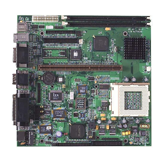
Page 16: Board Layout
DIM M2 DIM M1 CN11 CN35 CN33 CN37 CN36 E ISA1 CN13 JP 17 CN30 CN32 JP 15 JP 14 CN21 CN34 CN22 CP U1 CN10 JP 10 JP 12 CN14... -
Page 17: Board Dimensions
Board Dimensions MB-662 User Manual... -
Page 18: Chapter 2: Installation
Installation This chapter describes how to set up the main board hardware, including instruc- tions on setting jumpers and connecting peripherals, switches, and indicators. Be sure to read all the safety precautions before you begin the installation proce- dure. Chapter 2 Installation 9... -
Page 19: Setting Jumpers
A pair of needle-nose pliers may be helpful when working with jumpers. If you have any doubts about the best hardware configuration for your application, contact your local distributor or sales representa- tive before you make any changes. 10 MB-662 User Manual... -
Page 20: Cpu Installing And Upgrading
CPU installing and upgrading You can upgrade to a more powerful Celeron CPU at any time. Simply remove the old CPU, install the new one, and set the jumpers for the new CPU speed. Warning! Always disconnect the power cord from your chassis when you are working on it. - Page 21 Lift the CPU chip out. When you install a new CPU, be sure to adjust the board settings, such as CPU type and CPU clock. Improper settings may damage the CPU. 12 MB-662 User Manual...
-
Page 22: Installing Dram (Dimms)
Installing SDRAM (DIMMs) System Memory The upper edge of the MB-662 contains two sockets for 168 pins dual inline memory module (DIMM). The socket uses 3.3 V unbuffered synchronous (SDRAM). DIMM is available in capaci- ties of 16, 32, 64, 128, or 256 MB. The socket can be filled in the DIMM of any size, giving your MB-662 single board computer between 16 and 512 MB of memory. -
Page 23: Locating Jumpers And Connectors
DIM M2 DIM M1 CN11 CN35 CN33 CN37 CN36 E ISA1 CN13 JP 17 CN30 CN32 JP 15 JP 14 CN21 CN34 CN22 CP U1 CN10 JP 10 JP 12 CN14... -
Page 24: List Of Jumpers
List of Jumpers Jumpers allow users to manually customize system configurations to their suitable application needs. The following chart consist the list of each jumper function: J u m p e r s Label Function Clear CMOS Selection Power ON Switch Panel Type Selection LCD Panel Voltage Setting LCD Clock Signal Selection... -
Page 25: List Of Connectors
Digital I/O Connector CN30 COM3 Connector CN31 COM4 Connector CN32 COM1 Connector CN33 Joystick / MIDI Port CN34 Audio Connector for CD_IN CN35 Phone Jack for Line_OUT CN36 Phone Jack for MIC CN37 Phone Jack for Line_IN 16 MB-662 User Manual... -
Page 26: Clear Cmos (Jp1)
Clear CMOS Selection (JP1) Safety precautions in setting up clear CMOS must be taken, always place jumper on protect mode. In clearing CMOS, place jumper for just a second (follow clear CMOS illustration) then, immediately return jumper to protect mode. * Protect Clear CMOS Default... -
Page 27: Lcd Clock Signal Selection (Jp7)
* Default Ethernet Tx/Rx/Link LED Connector (JP8) With ethernet Tx/Rx/Link LED indicator, the ethernet status can be trace up through LED indicator readings. The pin definitions are listed as follows: Signal Signal Rx-LED Link LED Tx-LED 18 MB-662 User Manual... -
Page 28: Com4 Rs-232/422/485 Selection (Jp10)
COM4 RS-232/422/485 Selection (JP10) RI function or voltage selection configurations for COM3/COM2 can be set manually through jumper JP10. Jumper settings are illustrated as follows: * RI Function +5Vout +12Vout * RS-232 RS-422 RS-485 10 12 10 12 10 12 * Default Speaker/Buzzer (JP12) This onboard jumper provides users easy manual settings for on... -
Page 29: System Status Led Pin Header (Jp13)
Just follow the pin definition for each 7 LEDs illustrated below: Signal Pin Signal Power_ON LED CPU_fan LED System_fan LED HDD_access LED Low_temperature LED (option) 10 Vcc High_temperature LED (option) 12 Vcc LAN_access LED 14 Vcc 20 MB-662 User Manual... -
Page 30: Doc Address Selection (Jp15)
DiskOnChip (DOC) Address Selection (JP15) The DiskOnChip 2000 family of products provides a single chip solid-state flash disk in a standard 32-pin DIP package. The DiskOnChip 2000 is a solid-state disk with no moving parts, resulting in a significant reduction in power consumption and an increase in reliability. -
Page 31: Ir Touch Screen Power Pin Header (Jp16)
CPU you are using requires a ratio higher than 5.5X, it is most likely pre-locked. This table is provided for those who are using older PPGA Celeron processors that do not have pre-locked multiplier. Keyboard Lock (JP18) Keyboard Lock (CN18) Signal Signal KBLOCK 22 MB-662 User Manual... -
Page 32: Atx Power Connector (Cn2)
5VSB +12V Display Connectors (CN3) and (CN12) The MB-662's PCI SVGA interface can drive conventional CRT displays and is capable of driving a wide range of flat panel displays, including electroluminescent (EL), gas plasma, passive LCD, and active LCD displays. The board has two connectors to support these displays, one for standard CRT VGA monitors and one for flat panel displays. -
Page 33: Vga Display Connector (Cn3)
A standard conventional D-sub connector is equipped to interface with conventional CRT displays. Refer to pin definitions as follows: Signal GREEN BLUE Chassis GND Chassis GND Chassis GND Chassis GND Chassis GND DDDA H-SYNC V-SYNC DDCK 24 MB-662 User Manual... -
Page 34: Lcd Display Connector (Cn12)
LCD display connector (CN12) CN12 is a 50-pin, dual-in-line header used for flat panel displays. When the MB-662's power is applied, the control signal is low until just after the relevant flat panel signals are present. Configuration of the VGA interface is done completely via the software utility. -
Page 35: Usb Connector (Cn6)
USB Connector (CN6) MB-662 is equipped with a dual port USB connector. It acquires the new generation of plug and play ( Hot Plugging ) feature, for both low speed and high speed devices. It could also be expanded up to 127 connections through USB hub. -
Page 36: Floppy Drive Connector (Cn7, 9)
Floppy drive connector (CN7), FPC (CN9) You can attach up to two floppy drives to the mainboard controller. You can use any combination of 5¼" (360 KB and 1.2 MB) and/or 3½" (720 KB, 1.44 MB, and 2.88 MB) drives. A 34-pin daisy chain drive connector cable for (CN7) is required for a dual-drive system. -
Page 37: Irda Connector (Cn8)
1.) Plug infrared module into IrDA connector. Caution must be taken with the connector's orientation before plugging into IrDA connector. 2.) Enable infrared function in the BIOS system setup. IrDA connector (CN8) pin definitions: Signal Signal FIrRx IrTx IrRx CIrRx 28 MB-662 User Manual... -
Page 38: Floppy Drive Connector (Cn9)
Floppy Drive Connector (CN9) (FPC) Floppy Drive Connector (CN9) Signal Signal INDEX DRIVE SELECT 2 DISK CHANGE DENSITY SELECT MOTOR 0 DIRECTION STEP WRITE DATA WRITE GATE TRACK 0 WRITE PROTECT READ DATA HEAD SELECT Parallel Port 1 Connector (CN10) and Parallel Port 2 Connector (CN21) The mainboard is designed to support two parallel ports. - Page 39 Parallel Port 1 Connector (CN10), 25-pin D-sub Signal Signal /STB /ACK BUST /SLCT /AUTOFD /INIT /SLCTINI Parallel Port 2 Connector (CN21), 13x2 pin header Signal Signal /STB /AUTOFD /INIT /SLCTINI /ACK BUST SLCT 30 MB-662 User Manual...
-
Page 40: Keyboard And Mouse Connector (Cn11)
Keyboard and Mouse Connector (CN11) The MB-662 provides a keyboard connector which supports both a keyboard and a PS/2 style mouse. Please refer to the pin definitions listed below: Keyboard and Mouse Connector (CN11), Dual mini-din connector Signal Signal KB DATA... -
Page 41: Ethernet Connector (Cn14)
+12V fan speed sensor RJ-45 Ethernet Connector (CN14) MB-662 is outfitted with a standard RJ-45 LAN connector. With support from Realtek RTL8139C chipset using either 10Mbs or 100Mbs are possible through it's N-way auto-negotiation featured operation. Refer to the pin definitions listed below:... -
Page 42: Ide Hard Drive Connector (Cn16 & 17)
IDE Hard Drive Connectors Primary IDE Hard Drive Connector (CN16) Secondary IDE Hard Drive Connector (CN17) You can attach up to four Enhanced Integrated Device Electronics hard disk drives to the mainboard's internal controller. The main- board's IDE controller uses a PCI local-bus interface. This advance interface supports faster data transfer and allows the IDE hard drive to exceed 528 MB. - Page 43 DATA 1 DATA 14 DATA 0 DATA 15 SIGNAL GND IO WRITE IO READ IO CHANNEL READY IRQ14 IOCS16 ADDR 1 ADDR 0 ADDR 2 HARD DISK SELECT 0 HARD DISK SELECT 1 IDE ACTIVE MGND MVcc 34 MB-662 User Manual...
- Page 44 Secondary IDE Hard Drive Connector (CN17) Signal Signal IDE RESET DATA 7 DATA 8 DATA 6 DATA 9 DATA 5 DATA 10 DATA 4 DATA 11 DATA 3 DATA 12 DATA 2 DATA 13 DATA 1 DATA 14 DATA 0 DATA 15 SIGNAL GND IO WRITE...
-
Page 45: Serial Port Com1 (Cn22)
NRI1 LCD Inverter Backlight Power Connector (CN25) CN25 enables power transmission when connected from the main- board to the LCD panel for backlight lighting. Refer to the pin de- finitions below: Signal +5V ENB +12V ENB 36 MB-662 User Manual... -
Page 46: Digital I/O Connector (Cn29)
Digital I/O Connector (CN29) MB-662 offers digital I/O functions connector for easy access and link with digital devices. (Input 4031: GPI15 [bit7]; Input 4032: GPI17 [bit1], GPI18 [bit2], GPI19 [bit3]; Output 4036: GPO17 [bit1], GPO 18 [bit2], GPO19 [bit3], GPO20 [bit4] ) The pin definitions are... -
Page 47: Serial Port Com3 Connectors(Cn32)
COM1 (CN32) COM1 RS-232 (CN32) Signal Signal DCDA DSRA RXDA RTSA TXDA CTSA DTRA DTRA COM4 (CN31) COM4 RS-232/422/485 (CN31) Signal Signal DCDB DSRB RXDB RTSB TXDB CTSB DTRB IRIB 485TXD+ 485TXD- 422RXD- 422RXD- 38 MB-662 User Manual... -
Page 48: Joystick/Midi Port (Cn33)
Joystick / MIDI Port (CN33) MB-662 is equipped with a 4 in 1 connector and provides joystick / MIDI port. All designed for easy access to the users. Refer to the pin definitions below: Joystick / MIDI Port Connector (CN33) -
Page 49: Phone Jack For Line_Out (Cn35)
Signal Line_OUT Left Line_OUT Right Phone Jack for MIC (CN36) A standard phone jack is also provided for the users ease and con- venience. The pin definitions are listed below: MIC Phone Jack (CN36) Signal MIC_IN 40 MB-662 User Manual... -
Page 50: Phone Jack For Line_In (Cn37)
Phone Jack for Line_IN (CN37) The MB-662 is designed with line_OUT and for additional ease a line_IN connection is definitely needed. It also comes with stan- dard easy connection. Pin definitions below: Line_IN Phone Jack (CN37) Signal Line_IN Left Line_IN Right... -
Page 51: Chapter 3: Award Bios Setup
Award BIOS Setup This chapter describes how to configure the BIOS for the system. MB-662 User Manual... -
Page 52: Starting Setup
Starting setup The Award BIOS is immediately activated when you first turn on the computer. The BIOS reads system configuration information in CMOS RAM and begins the process of checking out the system and configuring it through the power-on self test (POST). When these preliminaries are finished, the BIOS seeks an operating system on one of the data storage devices (hard drive, floppy drive, etc.). -
Page 53: Setup Keys
CMOS, only for Option Page Setup Menu Load the default CMOS RAM value from BIOS default table, only for Option Page Setup Menu Load the default Reserved Reserved Save all the CMOS changes, only for Main Menu MB-662 User Manual... -
Page 54: Getting Help
Getting help Press F1 to pop up a small help window that describes the appro- priate keys to use and the possible selections for the highlighted item. To exit the Help Window press Esc or the F1 key again. In Case of Problems If, after making and saving system changes with Setup, you discover that your computer no longer is able to boot, the Award- BIOS supports an override to the CMOS settings that resets your... -
Page 55: Main Setup Menu
Password Setting BIOS versions that allow separate user and supervisor passwords, only the supervisor password permits access to Setup. The user password generally allows only power-on access. IDE HDD Auto Automatically detect and configure IDE hard Detection disk parameters. MB-662 User Manual... - Page 56 Load BIOS BIOS defaults are factory settings for the Defaults most stable, minimal-performance system operations. Load Setup Setup defaults are factory settings for Defaults optimal-performance system operations. Save & Exit Save settings in nonvolatile CMOS Setup RAM and exit Setup. Exit Without Abandon all changes and exit Setup.
-
Page 57: Standard Cmos Setup
Standard CMOS setup When you choose the STANDARD CMOS SETUP option from the INITIAL SETUP SCREEN menu, the screen below is dis- played. MB-662 User Manual... -
Page 58: Hard Disks
This standard setup menu allows users to configure system components such as the date, time, hard disk drive, floppy drive, display, and memory. Online help for each field can be accessed by pressing F1. Date and Time Configuration The BIOS determines the day of the week from the other date information. - Page 59 : The BIOS automatically determines the optimal mode. - Normal : Maximum number of cylinders, heads, and sectors supported are 1024, 16, and 63. - Large : For drives that do not support LBA and have more than 1024 cylinders. MB-662 User Manual...
- Page 60 - LBA (Logical Block Addressing): During drive accesses, the IDE controller transforms the data address described by sector, head, and cylinder number into a physical block address, significantly improving data transfer rates. For drives with greater than 1024 cylinders. Drive A Drive B Select the correct specifications for the diskette drive(s) installed in the computer.
- Page 61 CPU. Modern personal computers may contain up to 64 MB, 128 MB, or more. •Base Memory Typically 640 KB. Also called conventional memory. The DOS operating system and conventional applications use this area. MB-662 User Manual...
-
Page 62: Extended Memory
•Extended Memory Above the 1-MB boundary. Early IBM personal computers could not use memory above 1 MB, but current PCs and their software can use extended memory. •Other Memory Between 640 KB and 1 MB; often called High memory. DOS may load terminate-and-stay-resident (TSR) programs, such as device drivers, in this area, to free as much conventional memory as possible for applications. -
Page 63: Bios Features Setup
BIOS features setup By choosing the BIOS FEATURES SETUP option from the INITIAL SETUP SCREEN menu, the screen below is displayed. MB-662 User Manual... -
Page 64: Virus Warning
The displayed configuration is based on the manufacturer's SETUP DEFAULTS settings. Virus Warning When enabled, you receive a warning message if a program (specifically, a virus) attempts to write to the boot sector or the partition table of the hard disk drive. You should then run an anti- virus program. -
Page 65: Boot Sequence
MB (extended memory). When set to Fast, the system chipset controls Gate A20. When set to Normal, a pin in the keyboard controller controls Gate A20. Setting Gate A20 to Fast improves system speed, particularly with OS/2 and Windows. MB-662 User Manual... -
Page 66: Typematic Rate Setting
Typematic Rate Setting- Key strokes repeat at a rate determined by the keyboard controller. When enabled, the typematic rate and typematic delay can be selected. The choice: Enabled/Disabled Typematic Rate (Chars/Sec)- Sets the number of times a second to repeat a key stroke when you hold the key down. - Page 67 BIOS Features Setup screen may be occupied by other expansion card firmware. If an expansion peripheral in your system contains ROM-based firmware, you need to know the address range the ROM occupies to shadow it into the correct area of RAM. MB-662 User Manual...
-
Page 68: Chipset Features Setup
CHIPSET features setup By choosing the CHIPSET FEATURES SETUP option from the INITIAL SETUP SCREEN menu, the screen below is displayed. Chapter 3 Award BIOS Setup... - Page 69 When synchronous DRAM is installed, you can control the number of CLKs between when the SDRAMs sample a read command and when the contoller samples read data from the SDRAMs. Do not reset this field from the default value specified by the system designer. MB-662 User Manual...
-
Page 70: System Bios Cacheable
SDRAM Precharge Control When Enabled, all CPU cycles to SDRAM result in an All Banks Precharge Command on the SDRAM interface. DRAM Data Integrity Mode Select Non-ECC or ECC (error-correcting code), according to the type of installed DRAM. System BIOS Cacheable Selecting Enabled allows caching of the system BIOS ROM at F0000h-FFFFFh, resulting in better system performance. -
Page 71: Delayed Transaction
EMI. Enabling pulse spectrum spread modulation changes the extreme values from spikes to flat curves, thus reducing EMI. This benefit may in some cases be outweighed by problems with timing-critical devices, such as a clock-sensitive SCSI device MB-662 User Manual... - Page 72 High Limit Temperature Warning When the single board computer exceeds the high limit temperature warning level, the buzzer will sound and the LED will flash. Low Limit Temperature Warning When the single board computer exceeds the low limit temperature warning level, the buzzer will sound and the LED will flash. IN0, IN1, IN2, +5V,-5V,+12V,-12V These fields display the current voltage of up to seven voltage input lines, if your computer contains a monitoring system.
-
Page 73: Power Management Setup
Power management setup By choosing the POWER MANAGEMENT option from the INITIAL SETUP SCREEN menu, the screen below is displayed. MB-662 User Manual... -
Page 74: Power Management
The displayed configuration is based on the manufacturer's SETUP DEFAULTS settings. Power Management This option allows you to select the type (or degree) of power saving for Doze, Standby, and Suspend modes. This table describes each power management mode: Max Saving Maximum power savings. -
Page 75: Video Off Method
Doze Mode After the selected period of system inactivity, the CPU clock throttles to a small percentage of its duty cycle between 10 percent and 25 percent for most chipsets. All other devices still operate at full speed. MB-662 User Manual... -
Page 76: Standby Mode
Standby Mode After the selected period of system inactivity, the CPU clock stops, the hard drive enters an idle state, and the L2 cache enters a power- save mode. All other devices still operate at full speed. Suspend Mode After the selected period of system inactivity, the chipset enters a hardware suspend mode, stopping the CPU clock and possibly causing other system devices to enter power management modes. - Page 77 Reload Global Timer Events When Enabled, an event occurring on each device listed below restarts the global timer for Standby mode. IRQ3-7, 9-15, NMI Primary IDE 0 Primary IDE 1 Floppy Disk Serial Port Parallel Port MB-662 User Manual...
-
Page 78: Pnp/Pci Congfiguration Setup
PNP/PCI configuration setup By choosing the PNP/PCI CONFIGURATION SETUP option from the initial SETUP SCREEN menu, the screen below is displayed. Chapter 3 Award BIOS Setup... -
Page 79: Pnp Os Installed
IRQ resource. Assign IRQ for USB Select Enabled if your system has a USB controller and you have one or more USB devices connected. By selecting Disabled setting there is no IRQ resource for USB controller. MB-662 User Manual... -
Page 80: Load Bios Defaults/Load Setup Defaults
Load BIOS defaults/Load setup defaults LOAD BIOS DEFAULTS loads the default system values directly from ROM. The BIOS DEFAULTS provides the most stable settings, though they do not provide optimal performance. LOAD SETUP DEFAULTS, on the other hand, provides for maximum system performance. -
Page 81: Integrated Peripherals Setup
Integrated peripherals setup By choosing the INTEGRATED PERIPHERALS option from the initial SETUP SCREEN menu, the screen below is displayed. MB-662 User Manual... -
Page 82: Ide Hdd Block Mode
The displayed configuration is based on the manufacturer's SETUP DEFAULSTS settings. IDE HDD Block Mode Select Enabled only if your hard drives support block mode. IDE Primary Master/Slave UDMA UDMA (Ultra DMA) is a DMA data transfer protocol that utilizes ATA commands and the ATA bus to allow DMA commands to transfer data at a maximum burst rate of 33 MB/s. -
Page 83: Onboard Fdc Controller
In an infrated port mode, this field appears. Full-duplex mode permits simultaneous two-direction transmission. Half-duplex mode permits transmission in one direction only at a time. Select the value required by the IR device connected to the IR port. MB-662 User Manual... -
Page 84: Parallel Port Mode
Onboard Serial Ports (1, 2, 3, 4) Normally, the main board’s I/O chips will occupy a certain portion of memory space. For each I/O device the computer provides an I/O address. The more devices attached the more address needed to organize the memory storage areas. If all the I/O devices were run through the same address, your devices would come to a near halt. -
Page 85: Supervisor/User Password Setting
The difference between the two is that the supervisor password allows unrestricted access to enter and change the options of the setup menus, while the user password only allows entry to the program, but not modify options. MB-662 User Manual... - Page 86 When you select this function, a message appears at the center of the screen: ENTER PASSWORD: Type the password, up to eight characters, and press Enter. Typing a password clears any previously entered password from CMOS memory. Now the message changes: CONFIRM PASSWORD: Again, type the password and press Enter.
-
Page 87: Ide Hdd Auto Detection
The IDE HDD AUTO DETECTION utility can automatically detect the IDE hard disk installed in your system. You can use it to self-detect and/or correct the hard disk type configuration. You need to repeat the setup for each of the IDE combinations: MB-662 User Manual... -
Page 88: Save & Exit Setup
Save & exit setup If you select this option and press <ENTER>, the values entered in the setup utility will be recorded in the chipset's CMOS memory. The microprocessor will check this every time you turn your system on and compare this to what it finds as it checks the system. This record is required for the system to operate. -
Page 89: And Utilities
Flat Panel/CRT Controller Display Drivers and Utilities This chapter provides information about: • Driver types and installation MB-662 User Manual... -
Page 90: Software Drivers
Software Drivers This chapter describes the operation and installation of the display drivers supplied on the Supporting CD-ROM that are shipped with your product. The onboard VGA adapter is based on the CHIPS VGA Flat Panel/CRT controller and is fully IBM VGA compatible. This controller offers a large set of extended functions and higher resolutions. -
Page 91: Necessary Prerequisites
Make sure you know the version of the application for which you are installing drivers. The Supporting CD-ROM contain drivers for several versions of certain applications. For your driver to operate properly, you must install the driver for your version of the application program. MB-662 User Manual... -
Page 92: Windows 95
Windows® 95 ® ® These drivers are designed to work with Microsoft Windows . You ® can install these drivers through the Windows operating system. Driver installation ® 1. Install Windows 95 as you normally would for a VGA display. Click the Start button, go to Settings and click on Control Panel. - Page 93 Click the setting button, then click the Advanced Properties icon into the Advanced Display properties windows, show as figure2: figure 2 MB-662 User Manual...
- Page 94 click on Change Display Type. In the Change Display Type window, click on the Change button under Adapter Type into the select Device window show as figure 3: This will bring up the Select Device window. figure 3 Chapter 4 Driver Installation...
- Page 95 Win95 driver "chips95.inf" in the Supporting CD- ROM: cd-rom: \CD ROM\model name\driver\vga driver \win95\chips95.inf and then click OK. "cd-rom" : the drive letter of your CD-ROM drive "model name" : the model number of your product MB-662 User Manual...
- Page 96 The name of the Chips And Tech "69000 PCI " driver will appear highlighted in the Models list boxfhow as figure. Click OK to start the driver installation show as figure 5: figure 5 Chapter 4 Driver Installation...
- Page 97 3. Once the installation is complete, the Advanced display Properties window will reappear. Show as figure 6: figure 6 MB-662 User Manual...
- Page 98 Click on close to close the window. Then the Display Properties window will reappear. Show as figure 7: figure 7 Chapter 4 Driver Installation...
- Page 99 Click on Apply. Restart the system for the new settings to take effect, show as figure 8: figure 8 MB-662 User Manual...
-
Page 100: Windows 3.1
Windows® 3.1 These drivers are designed to work with Microsoft Windows Version 3.1. You should install these drivers through Windows. Driver installation 1. Install Windows as you normally would for a VGA display. Run Windows to make sure that it is working correctly. 2. -
Page 101: Os/2
4. When the Display Driver Install window appears, select Primary Display and then select OK. 5. When the Primary Display Driver List window appears, select "Chips and Technologies 69000" from the list of adapter types, then select OK or install the video driver. MB-662 User Manual... - Page 102 6. When the installation is complete, you will need to shut down and then restart the system for the changes to take effect. Make sure to remove the installation diskette before restarting the system. Chapter 4 Driver Installation...
-
Page 103: Windows 3.51
"model name" : the model number of your product Select the adapter "Chips and Tech 69000PCI" and click OK. Click on Install to install the selected driver. Once the installation is complete, shut down and restart the system. MB-662 User Manual... -
Page 104: Windows 98
Windows® 98 Driver installation ® 1. Install Windows 98 as you normally would for a VGA display. Click the Start button, go to Settings and click on Control Panel icon. Then choose the Display and double click on the icon. In the Display Properties window, click the Setting button from the Display Type window, and click on Advanced button in the change display window. -
Page 105: Windows Nt 4.0
3. Once the installation is complete, the Change Display Type window will reappear. Click on close to close the window. Then the Display Properties window will reappear. Click on Apply. Restart the system for the new settings to take effect. MB-662 User Manual... -
Page 106: Chapter 5: Ethernet Software Configuration
Ethernet Software C o n f i g u r a t i o n This chapter describes how to configure the Etherent Card to match your applica- tion requirements. Chapter 5 Software Configuration... -
Page 107: Windows 98 Driver Installation
8139C driver will appear highlighted in the Modules list box. Select Realtech 8139C and Click OK. Click OK to start the driver installation. Once the installation is complete, restart the system for the new settings to take effect. MB-662 User Manual... -
Page 108: Ethernet Software Configuration
Ethernet software configuration The onboard Ethernet interface supports all major network operating systems. I/O addresses and interrupts are easily configured via the Award BIOS Setup. To configure the medium type, to view the current configuration, or to run diagnostics, please refer to the following instruction: 1. -
Page 109: Chapter 6: Audio Software Configuration
Audio Setup This MB 662 is equipped with an audio interface that records and playback CD- quality audio. This chapter provides instructions for installing the software drivers on the included CDROM. MB-662 User Manual... -
Page 110: Audio Software Configuration
ESS Labs, Inc. The audio interface can record, com- press, and play back voice, sound, and music with built-in mixer control. The MB-662 on board audio interface also supports the Plug and Play (PnP) standard and provides PnP configuration for the audio, FM, and ®... - Page 111 Windows 98 CD-ROM disk when you install the joystick or MIDI device. Note: If the file being copied is older than the file currently existing in your system, we suggest you to keep the existing file. MB-662 User Manual...
- Page 112 4. Windows 98 makes changes to the system settings and begins detecting the following new hardware components: · Gameport Joystick · ES1938 PCI Audio Drive · ES1938 DOS Emulation 5. Upon initial installation, the setup process begins setting up the software.
-
Page 113: Windows Nt 4.0
"cd-rom" : the drive letter of your CD-ROM drive "model name" : the model number of your product 2. After the ESS Solo-1 Audio Drive Installation window shows up, click on the Next button. 3. Simply follow the instructions to finish the installation. MB-662 User Manual... -
Page 114: Appendix A: Programming The Watchdog Timer
Programming Watchdog Timer The mainboard is equipped with a watchdog timer that resets the CPU or generates an interrupt if processing comes to a standstill for whatever reason. This feature ensures system reliability in industrial stand-alone and unmanned environments. Appendix A Programming the Watchdog Timer... -
Page 115: Programming The Watchdog Timer
-- output value 0 to port 0x443 outportb(0x443, 0); // disable watchdog timer 4. To ebable or refresh watchdog timer(the watchdog timer will return to its initial value, then count down): -- access the I/O port 0x443, e.g. MB-662 User Manual... -
Page 116: Configuration Register
outportb(0x443, data); // refresh watchdog timer * note: if you want to refresh the watchdog timer, you have to disable it first. Demo program outportb(0x444, 3): // set time-out event to reset-system outportb(0x443x 10); // set time-out interval to 10 seconds customer_job();...
Need help?
Do you have a question about the MB-662 and is the answer not in the manual?
Questions and answers