Table of Contents
Advertisement
Quick Links
Advertisement
Table of Contents

Related Manuals for Aaeon MIX-Q370D1


Summary of Contents for Aaeon MIX-Q370D1
- Page 1 MIX-Q370D1...
- Page 2 E14570 Second Edition July 2018 Copyright Notice This document is copyrighted, 2018. All rights are reserved. The original manufacturer reserves the right to make improvements to the products described in this manual at any time without notice. No part of this manual may be reproduced, copied, translated, or transmitted in any form or by any means without the prior written permission of the original manufacturer.
-
Page 3: Table Of Contents
Contents Chapter 1: Product overview Package contents ................. 1-1 Features ..................1-1 1.3 Specifications ................1-2 Chapter 2: Motherboard information Before you proceed ..............2-1 Motherboard layout ..............2-2 Screw size ..................2-4 2.3.1 Component side .............. 2-4 2.3.2 Solder side ..............2-5 Central Processing Unit (CPU) ........... - Page 4 Chipset menu ................3-9 3.4.1 System Agent (SA) Configuration ........3-9 3.4.2 PCH-IO Configuration ............. 3-9 Security menu ................3-10 3.5.1 Administrator Password ..........3-10 3.5.2 User Password .............. 3-10 Boot menu .................. 3-11 3.6.1 Boot Configuration ............3-11 3.6.2 Boot Option Priorities ............ 3-11 Save &...
-
Page 5: Chapter 1: Product Overview
Chapter 1 Product overview Package contents Check your industrial motherboard package for the following items. 1 x Industrial Motherboard 1 x SATA 6.0Gb/s cable 1 x COM cable 1 x I/O Shield 1 x Support CD If any of the above items is damaged or missing, contact your distributor or sales representative immediately. -
Page 6: Specifications
Power requirement 12VDC Operating temperature F~140 F (0 C~60 Operating humidity 0%~90% relative humidity, non-condensing Certificate CE & FCC Form factor Mini ITX Form Factor: 6.7”x 6.7” (170mm x 170mm) Weight 1.1 lb (0.5 Kg) (continued on the next page) MIX-Q370D1... - Page 7 Storage 4 x SATA 6.0Gb/s ports, support RAID 0/ 1/ 5/ 10 4-pin SATA power connector (5V, 12V @1A) 1 x M.2 M-Key slot (22 x 80mm) at the bottom side, mSATA & PCIe 4 x USB 3.1 Gen 2 ports (4 ports at the rear panel) 6 x USB 2.0 ports (6 ports at mid-board) Display 2 x DP, 1 x eDP, 1 x LVDS...
- Page 8 Others OS support Windows 10 64-bit (CFL does not support 32-bit OS) ® Linux Ubuntu16.04.02/Kernel4.8.0 Accessories 1 x SATA cable 1 x SATA power cable 1 x I/O shield 1 x Support DVD NOTE: Specifications are subject to change without notice. MIX-Q370D1...
-
Page 9: Chapter 2: Motherboard Information
Chapter 2 Motherboard information Before you proceed Take note of the following precautions before you install motherboard components or change any motherboard settings. CAUTION! • Unplug the power cord from the wall socket before touching any component. • Before handling components, use a grounded wrist strap or touch a safely grounded object or a metal object, such as the power supply case, to avoid damaging them due to static electricity. • Hold components by the edges to avoid touching the ICs on them. • Whenever you uninstall any component, place it on a grounded antistatic pad or in the bag that came with the component. -
Page 10: Motherboard Layout
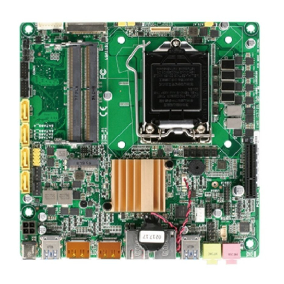
DDR4 DIMM_A1 (64bit, 260-pin module) Place this side BOTTOM:M2_TYPE_M1 towards the rear of the chassis Intel ® LAN1 Q370 WGI219LM LAN2 LGA1151 BATTERY_H USB3_12 WGI210AT 128Mb BIOS SATA_PWR LINE-OUT USB56 2280 AAFP USB78 US910 AMP_CON MIC-IN DMIC PCIEX4_1 MIX-Q370D1 MIX-Q370D1... - Page 11 Connectors/Jumpers/Slots Page 12VDC connector (4-pin EATX_PWR2) 2-18 CPU and chassis fan connectors (4-pin CPU_FAN, 4-pin CHA_FAN) 2-19 System panel connector (10-1 pin F_PANEL) 2-21 SATA 6.0Gb/s connectors (7-pin SATA6G_1~4) 2-19 DDR4 DIMM slots 2-11 Digital I/O connector (10-pin DIO) 2-22 Serial port connector (10-pin COM1) 2-22 COM1 operating mode selection jumpers (2-pin J1/J2/J3/J4) 2-13 Inverter voltage selection (3-pin LJ2) 2-15 10. LVDS panel voltage selection (3-pin LJ1) 2-15 11. Inverter backlight control mode selection (3-pin LJ3) 2-15 12. COM1 Ring/+5V/+12V selection jumper (6-pin COM1_V1) 2-13 13. Backlight inverter power connector (8-pin INV) 2-24 14. Embedded DisplayPort (40-pin eDP1) 2-25 15. LVDS connector (40-pin LVDS) 2-24 16. Clear RTC RAM (3-pin CLRTC1) 2-12 17.
-
Page 12: Screw Size
168.02 159.23 167.64 152.64 152.18 147.59 143.15 131.26 118.75 117.92 109.75 92.73 83.84 75.71 67.44 57.14 66.30 51.82 58.69 56.25 45.45 42.10 46.10 32.00 38.71 31.05 30.04 29.34 23.94 27.36 11.00 16.09 10.54 16.03 14.46 0.00 10.54 16.34 2.25 MIX-Q370D1... -
Page 13: Solder Side
2.3.2 Solder side 170.18 165.10 165.10 164.21 156.87 153.95 92.94 92.94 81.86 81.86 62.96 52.96 42.96 33.02 10.16 0.00 Chapter 2: Motherboard information... -
Page 14: Central Processing Unit (Cpu)
Central Processing Unit (CPU) This motherboard comes with an Intel 8th Generation (Coffee Lake S) Core™ i7 / ® i5 / i3, Pentium LGA 1151 socket processor. ® MIX-Q370D1 MIX-Q370D1 CPU socket LGA1151 IMPORTANT: Unplug all power cables before installing the CPU. CAUTION! • Upon purchase of the motherboard, ensure that the PnP cap is on the socket and the socket contacts are not bent. Contact your retailer immediately if the PnP cap is missing, or if you see any damage to the PnP cap/socket contacts/motherboard components. • Keep the cap after installing the motherboard. The manufacturer will process Return Merchandise Authorization (RMA) requests only if the motherboard comes with the cap on the LGA1151 socket. • The product warranty does not cover damage to the socket contacts resulting from incorrect CPU installation/removal, or misplacement/loss/ incorrect removal of the PnP cap. MIX-Q370D1... -
Page 15: Installing The Cpu
2.4.1 Installing the CPU CAUTION! Ensure that you install the correct CPU designed for LGA1151 only. DO NOT install a CPU designed for LGA1155 and LGA1156 sockets on the LGA1151 socket. Chapter 2: Motherboard information... - Page 16 MIX-Q370D1...
-
Page 17: Cpu Heatsink And Fan Assembly Installation
2.4.2 CPU heatsink and fan assembly installation CAUTION! Apply the Thermal Interface Material to the CPU heatsink and CPU before you install the heatsink and fan if necessary. To install the CPU heatsink and fan assembly Chapter 2: Motherboard information... - Page 18 To uninstall the CPU heatsink and fan assembly MIX-Q370D1 2-10...
-
Page 19: System Memory
System memory This motherboard comes with two Double Data Rate 4 (DDR4) Small Outline Dual Inline Memory Modules (SO-DIMM) sockets.The figure illustrates the location of the DDR4 DIMM sockets: DIMM_B1 DIMM_A1 MIX-Q370D1 MIX-Q370D1 260-pin DDR4 DIMM sockets NOTE: Use the DIMM_A1 slot when inserting only one SO-DIMM. Installing a DIMM To install a DIMM To remove a DIMM Chapter 2: Motherboard information 2-11... -
Page 20: Jumpers
Jumpers Clear RTC RAM (3-pin CLRTC1) This jumper allows you to clear the Real Time Clock (RTC) RAM in CMOS. You can clear the CMOS memory of system setup parameters by erasing the CMOS RTC RAM data. The onboard button cell battery powers the RAM data in CMOS, which include system setup information such as system passwords. MIX-Q370D1 MIX-Q370D1 Clear RTC RAM To erase the RTC RAM: 1. Turn OFF the computer and unplug the power cord. 2. Move the jumper cap from pins 1-2 (default) to pins 2-3. Keep the cap on pins 2-3 for about 5~10 seconds, then move the cap back to pins 1-2. 3. Plug the power cord and turn ON the computer. 4. Hold down the <Del> key during the boot process and enter BIOS setup to reenter data. CAUTION! Except when clearing the RTC RAM, never remove the cap on CLRTC jumper default position. Removing the cap will cause system boot failure! NOTES: • If the steps above do not help, remove the onboard battery and move the jumper again to clear the CMOS RTC RAM data. After clearing the CMOS, reinstall the battery. - Page 21 MIX-Q370D1 COM1 Ring/+5V/+12V Selection Setting Pins +12V Ring (Default) COM1 operating mode selection jumpers (2-pin J1/J2/J3/J4) J1、J2、J3、J4 RS232 (Default) RS485/RS422 with terminator MIX-Q370D1 MIX-Q370D1 COM1 operating mode selection (J1、J2、J3、J4) Setting Pins RS232 Open jumpers J1, J2, J3 and J4 (Default) RS485/RS422 with terminator Short-circuit jumpers J1, J2, J3 and J4 Chapter 2: Motherboard information...
- Page 22 AT/ATX mode selection (3-pin AT_ATX) AT_ATX ATX mode AT mode (Default) MIX-Q370D1 MIX-Q370D1 AT/ATX mode selection Pins ATX mode (Default) AT mode Chassis intrusion jumper (4-1 pin CHASSIS) This connector is for a chassis-mounted intrusion detection sensor or switch. Connect one end of the chassis intrusion sensor or switch cable to this connector. The chassis intrusion sensor or switch sends a high-level signal to this connector when a chassis component is removed or replaced. The signal is then generated as a chassis intrusion event.
- Page 23 Inverter voltage selection (3-pin J2) +12V (Default) MIX-Q370D1 MIX-Q370D1 Inverter voltage selection Setting Pins DC Voltage Control (Default) PWM Control Inverter backlight control mode selection (3-pin LJ3) DC CTL PWM CTL (Default) MIX-Q370D1 MIX-Q370D1 Inverter backlight control mode selection Setting Pins +12V +5V (Default) Chapter 2: Motherboard information 2-15...
-
Page 24: Onboard Leds
Onboard LEDs Standby Power LED The motherboard comes with a standby power LED that lights up to indicate that the system is ON, in sleep mode, or in soft-off mode. This is a reminder that you should shut down the system and unplug the power cable before removing or plugging in any motherboard component. The illustration below shows the location of the onboard LED. LED_5V Standby Power Powered Off MIX-Q370D1 MIX-Q370D1 Onboard LEDs MIX-Q370D1 2-16... -
Page 25: Connectors
Connectors 2.8.1 Rear panel connectors DC power connector. Insert the power adapter into this port. USB 3.1 Gen 2 ports. These 9-pin Universal Serial Bus (USB) ports connect to USB 3.1 Gen 2 devices. NOTES: • USB 3.1 Gen 2 devices can only be used for data storage. • Due to the design of the Intel 300 series chipset, all USB devices ® connected to the USB 2.0 and USB 3.1 Gen 2 ports are controlled by the xHCI controller. Some legacy USB devices must update their firmware for better compatibility. • We strongly recommend that you connect USB 3.1 Gen 2 devices to USB 3.1 Gen 2 ports for a faster and better performance from your USB 3.1 Gen 2 devices. DisplayPort connectors. This port connects a device with DisplayPort connector. LAN (RJ-45) ports. These ports allow Gigabit connection to a Local Area Network (LAN) through a network hub. Refer to the table below for the LAN port LED indications. LAN port LED indications Speed Activity Link ACT/LINK LED... -
Page 26: Internal Connectors
2.8.2 Internal connectors Internal power connectors (4-pin EATX_PWR2) This connector is for an EATX power supply plug. The power supply plug is designed to fit this connector in only one orientation. Find the proper orientation and push down firmly until the connector completely fits. EATX_PWR2 PIN 1 MIX-Q370D1 MIX-Q370D1 1 x 4-pin (2x2) internal power connector IMPORTANT: • For a fully configured system, we recommend that you use a power supply unit (PSU) that complies with ATX 12V Specification 2.0 (or later version). • We recommend that you use a PSU with higher power output when configuring a system with more power-consuming devices. The system may become unstable or may not boot up if the power is inadequate. Speaker out connector (4-pin AMP_CON) The 4-pin connector is for the chassis-mounted speaker. AMP_CON PIN 1 MIX-Q370D1 MIX-Q370D1 Audio stere. - Page 27 MIX-Q370D1 Fan connectors CAUTION: Do not forget to connect the fan cables to the fan connectors. Insufficient air flow inside the system may damage the motherboard components. These are not jumpers! Do not place jumper caps on the fan connectors! SATA 6.0Gb/s connectors (7-pin SATA6G_1~4) These connectors connect to Serial ATA 6.0 Gb/s hard disk drives via Serial ATA 6.0 Gb/s signal cables. MIX-Q370D1 MIX-Q370D1 SATA 6.0Gb/s connectors IMPORTANT: When using hot-plug and NCQ, set the SATA Mode Selection item in the BIOS to [AHCI]. See section 3.3.3 SATA Configuration for details. Chapter 2: Motherboard information 2-19...
- Page 28 USB 2.0 connectors (10-pin USB56, USB78 and USB910) These USB connectors comply with USB 2.0 specifications. USB56 USB78 USB910 PIN 1 PIN 1 PIN 1 MIX-Q370D1 MIX-Q370D1 USB2.0 connectors Never connect a 1394 cable to the USB connector. Doing so will damage the motherboard. BIOS programmable connector (8-pin SPI_1) Use this connector to flash the BIOS ROM. SPI_1 (NC) (NC) S_SPI_MISO_2Q S_SPI_MOSI_2Q S_SPI_CS1#Q S_SPI_CLK_2Q +3V_SPI PIN 1 MIX-Q370D1 MIX-Q370D1 BIOS Programmable connector MIX-Q370D1 2-20...
- Page 29 System panel connectors (10-1 pin F_PANEL) This connector supports several chassis-mounted functions. F_PANEL +PWR LED- PWR_BTN PIN 1 +HDD_LED- RESET MIX-Q370D1 MIX-Q370D1 System panel connector • System power LED (2-pin PWR_LED) This 2-pin connector is for the system power LED. Connect the chassis power LED cable to this connector. The system power LED lights up when you turn on the system power, and blinks when the system is in sleep mode. • Hard disk drive activity LED (2-pin HDD_LED) This 2-pin connector is for the HDD Activity LED. Connect the HDD Activity LED cable to this connector. The IDE LED lights up or flashes when data is read from or written to the HDD.
- Page 30 Serial port connector (10-pin COM1) This connector is for serial (COM) ports. Connect the serial port module cable to this connector, then install the module to a slot opening at the back of the system chassis. COM1 PIN 1 MIX-Q370D1 MIX-Q370D1 Serial port connector NOTE: The COM module is purchased separately. Digital I/O connector (10-pin DIO) This connector includes 8 I/O lines (In/Out programmable). All of the Digital I/O lines are programmable and each I/O pin can be individually programmed to support various devices. PIN 1 MIX-Q370D1 MIX-Q370D1 Digital I/O connector NOTE: To configure the I/O pins in BIOS, go to the Advanced tab > Digital IO Port Configuration. See section 3.3.10 Digital IO Port Configuration for details.
- Page 31 10. M.2 E-Key and M-Key slots These sockets allow you to install an M.2 (NGFF) module. M.2(SOCKET3) M.2_TYPE_E1 2230 M.2_TYPE_M1(BOTTOM) 2280 MIX-Q370D1 MIX-Q370D1 M.2(SOCKET3)s NOTES: • The M.2 SSD module is purchased separately. • The M.2 E-key slot supports type 2230 PCIe/USB Wi-Fi module. • The M.2 M-key slot supports type 2280 SATA/PCIe storage devices. 11. Battery connector (2-pin BATTERY_H) This connector is for the lithium CMOS battery. BATTERY_H PIN 1 MIX-Q370D1 MIX-Q370D1 Battery Holder connector Chapter 2: Motherboard information 2-23...
- Page 32 LVDS1_D2+ LVDS1_D3- LVDS1_D3+ LVDS0_D0- LVDS0_D0+ LVDS0_D1- LVDS0_D1+ LVDS0_D2- LVDS0_D2+ LVDS0_D3- LVDS0_D3+ PIN 1 PIN 1 MIX-Q370D1 MIX-Q370D1 LVDS connector 13. Backlight inverter power connector (8-pin INV) Connect the backlight inverter power cable to this connector. INV1 BLDN#_R BLUP#_R +BLVCC +BLVCC VCON INV_ENABKL PIN1 MIX-Q370D1 MIX-Q370D1 Inverter connector IMPORTANT: The backlight inverter power connector supports 1A current to the maximum.
- Page 33 +V_PANEL +V_PANEL +V_PANEL eDP_HPD_RRR BKLTEN_R BKLTCTL_R +BLVCC +BLVCC +BLVCC +BLVCC PIN 40 MIX-Q370D1 MIX-Q370D1 Embedded Display Port 15. SATA power connector (4-pin SATA_PWR) This connector is for the SATA power cable. The power cable plug is designed to fit this connector in only one orientation. Find the proper orientation and push down firmly until the connector completely fit. SATA_PWR PIN 1 MIX-Q370D1 MIX-Q370D1 SATA power connector IMPORTANT: The SATA power connector supports 1A current to the maximum. Chapter 2: Motherboard information...
- Page 34 16. DMIC connector (5-1 pin DMIC) The DMIC connector is for connecting the digital microphone module used in All-in-One chassis. DMIC MIX-Q370D1 PIN 1 MIX-Q370D1 DMIC connector 17. Front panel audio connector (10-1 pin AAFP) This connector is for a chassis-mounted front panel audio I/O module that supports HD Audio audio standard. Connect one end of the front panel audio I/O module cable to this connector. AAFP MIX-Q370D1 MIX-Q370D1 Front panel audio connector IMPORTANT: We recommend that you connect a high-definition front panel audio module to this connector to avail of the motherboard’s high-definition audio capability. MIX-Q370D1 2-26...
-
Page 35: Chapter 3: Bios Setup
Chapter 3 BIOS setup BIOS setup Use the BIOS Setup to update the BIOS or configure settings. The BIOS screens include navigation keys and help to guide you in using the BIOS Setup program. Entering BIOS Setup at startup To enter BIOS Setup at startup: Press <Delete>... -
Page 36: Main Menu
Be cautious when changing the settings of the Advanced menu items. Incorrect field values can cause the system to malfunction. Case Open Warning [Disabled] Allows you to enable or disable case open warning function. Configuration options: [Disabled] [Enabled] [Clear] MIX-Q370D1... -
Page 37: Cpu Configuration
3.3.1 CPU Configuration The items in this menu show CPU-related information the BIOS automatically detects. The items shown in the submenu may be different depending on the type of CPU installed. Hyper-threading [Enabled] The Intel Hyper-Threading Technology allows a hyper-threading processor to appear as two logical processors to the operating system, allowing the operating system to schedule two threads or processes simultaneously. -
Page 38: Sata Configuration
The USB Devices item lists auto-detected values. If no USB device is detected, the item shows None. Legacy USB Support [Enabled] [Enabled] Enables the support for USB devices on legacy operating systems (OS). [Disabled] USB devices are only available when running BIOS Setup. MIX-Q370D1... -
Page 39: Hardware Monitor
[Auto] Allows the system to detect the presence of USB devices at startup. If detected, the USB controller legacy mode is enabled. If no USB device is detected, the legacy USB support is disabled. XHCI Hand-off [Enabled] [Enabled] Enables the support for operating systems without an XHCI hand-off feature. - Page 40 Determines the amount of time Fan Out takes to decrease its value by one step. Input value range: [0~255] Fan Out Step Up Time [10] Determines the amount of time Fan Out takes to increase its value by one step. Input value range: [0~255] MIX-Q370D1...
-
Page 41: Sio Configuration
Fan Out Step Down Time [10] Determines the amount of time Fan Out takes to decrease its value by one step in intervals of 0.1 seconds. Input value range: [0~255] 3.3.6 SIO Configuration The items in this menu allow you to configure Super IO settings. [*Active*] Serial Port Use this device [Enabled] Allows you to enable or disable this logical device. -
Page 42: Digital Io Port Configuration
The items listed in this screen configure Digital IO settings. DIO Port1~Port4 [Output], DIO Port5~Port8 [Input] Configuration options: [Input] [Output] The following item appears only when you set DIO Port1~8 to [Output]. Output Level [High] Configuration options: [High] [Low] MIX-Q370D1... -
Page 43: Chipset Menu
Chipset menu The Chipset menu items allow you to change configuration options for the North Bridge and South Bridge. 3.4.1 System Agent (SA) Configuration MAX TOLUD [Dynamic] Allows you to select the maximum memory size of TOLUD (Top of Low Usable DRAM). Configuration options: [Dynamic] [1 GB] [1.25 GB] [1.5 GB] [1.75 GB] [2 GB] [2.25 GB] [2.5 GB] [2.75 GB] [3 GB] [3.25 GB] [3.5 GB] Primary Display [Auto] Allows you to decide which graphics controller to use as the primary boot device. -
Page 44: Security Menu
To change a user password: Select the User Password item and press <Enter>. From the Enter Current Password box, key in the current password, then press <Enter>. From the Create New Password box, key in a new password, then press MIX-Q370D1 3-10... -
Page 45: Boot Menu
<Enter>. Confirm the password when prompted. To clear the user password, follow the same steps as in changing a user assword, but press <Enter> when prompted to create/confirm the password. After you clear the password, the User Password item on top of the screen shows Not Installed. Boot menu The Boot menu items allow you to change the system boot options. - Page 46 MIX-Q370D1 3-12...
-
Page 47: Appendix
Check local regulations for disposal of electronic products. DO NOT throw the mercury-containing button cell battery in municipal waste. This symbol of the crossed out wheeled bin indicates that the battery should not be placed in municipal waste. MIX-Q370D1... - Page 48 ○ ○ ○ ○ 外部信號連接頭 × ○ ○ ○ ○ ○ 及線材 中央處理器與內 × ○ ○ ○ ○ ○ 存 本表格依據 SJ/T 11364 的規定編制。 ○: 表示該有害物質在該部件所有均質材料中的含量均在 GB/T 26572 規 定的限量要求以下。 ×: 表示該有害物質至少在該部件的某一均質材料中的含量超出 GB/T 26572 規定的限量要求,然該部件仍符合歐盟指令 2011/65/EU 的 規范。 備註:此產品所標示之環保使用期限,係指在一般正常使用狀況下。 MIX-Q370D1...
Need help?
Do you have a question about the MIX-Q370D1 and is the answer not in the manual?
Questions and answers
Hello. Upon re-seating the RAM, when placing the top chip, the motherboard beeps 6 times. It works without the second chip, but I need both to work. Please help.