Table of Contents
Advertisement
Quick Links
Advertisement
Table of Contents

Related Manuals for Aaeon MIX-ALND1


Summary of Contents for Aaeon MIX-ALND1
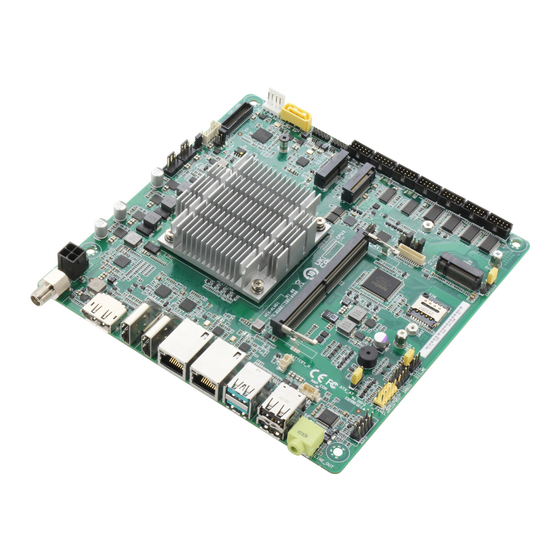
- Page 1 MIX-ALND1...
- Page 2 E22260 First Edition July 2023 Copyright Notice This document is copyrighted, 2023. All rights are reserved. The original manufacturer reserves the right to make improvements to the products described in this manual at any time without notice. No part of this manual may be reproduced, copied, translated, or transmitted in any form or by any means without the prior written permission of the original manufacturer.
-
Page 3: Table Of Contents
Contents Chapter 1 Product overview Package contents ................. 1-1 Features ..................1-1 1.3 Specifications ................1-2 Chapter 2 Motherboard information Before you proceed ..............2-1 Motherboard layout ..............2-2 Screw size ..................2-4 2.3.1 Component side .............. 2-4 2.3.2 Solder side ..............2-5 Central Processing Unit (CPU) ........... - Page 4 Contents 3.3.10 Power Management ............3-10 3.3.11 Digital IO Port Configuration ......... 3-11 Chipset menu ................3-11 3.4.1 System Agent (SA) Configuration ......... 3-11 3.4.2 PCH-IO Configuration ........... 3-12 Security menu ................3-12 3.5.1 Administrator Password ..........3-12 3.5.2 User Password .............. 3-13 3.5.3 Secure Boot ..............3-13 Boot menu ..................
-
Page 5: Chapter 1 Product Overview
Chapter 1 Product overview Package contents Check your industrial motherboard package for the following items. 1 x Industrial Motherboard 1 x SATA Cable 1 x SATA Power Cable 1 x I/O Shield NOTE: If any of the above items is damaged or missing, contact your distributor or sales representative immediately. -
Page 6: Specifications
Up to 4096 x 2160 @ 60Hz DisplayPort Up to 4096 x 2160 @ 60Hz LVDS Up to 1920 x 1080 @ 60Hz, Daul Channel 18/24 bit Up to 1920 x 1080 @ 60Hz Backlight control PWM mode control (continued on the next page) MIX-ALND1... - Page 7 Internal I/O Storage 1 x SATA (6.0Gb/s) port 1 x M.2 M key (2280/2242), [PCIex1/SATA] Serial port 2 x RS-232/422/485 ports (support 5V/12V/RI option) 4 x RS-232 ports 2 x USB 2.0 headers support 2 additional USB2.0 ports Display I/O 1 x 40-pin LVDS/eDP connector with Inverter (via CH7513) 1 x CPU Fan header (4-pin) 1 x Chassis Fan header (4-pin)
- Page 8 MIX-ALND1...
-
Page 9: Chapter 2 Motherboard Information
Chapter 2 Motherboard information Before you proceed Take note of the following precautions before you install motherboard components or change any motherboard settings. CAUTION! • Unplug the power cord from the wall socket before touching any component. • Before handling components, use a grounded wrist strap or touch a safely grounded object or a metal object, such as the power supply case, to avoid damaging them due to static electricity. -
Page 10: Motherboard Layout
M2_TYPE_E of the chassis LAN1 M2_TYPE_M 8111H LAN2 8111H DDR5 SO-DIMM_A1 (64bit, 260-pin module) 256Mb BIOS COM1_V1 USB31_12 BATTERY_H Super 2242 COM2_V1 USB2_56 LINE_OUT ATX_AT 2242 F_PANEL ISH_I2C CLRTC 3052 3042 AAFP 2280 SMBUS DIS_ME CHASSIS MIX-ALND1... - Page 11 Connectors/Jumpers Page ATX Power connector (4-pin EATX_PWR) 2-14 Intel Alder lake - N proccessor ® LVDS T-con IC Power Selection jumper (PNL_PWR) 2-12 CPU and System Fan headers (4-pin CPU_FAN, 4-pin SYS_FAN) 2-15 LVDS Panel Power Selection jumper (3-pin BKL_PWR) 2-10 LVDS Panel Backlight Power header (5-pin INV) 2-21...
-
Page 12: Screw Size
Screw size 2.3.1 Component side 167.62 166.75 165.62 164.36 157.71 157.45 137.45 128.52 131.54 127.59 126.30 125.35 118.40 116.79 107.70 96.77 85.36 67.82 56.26 44.45 47.99 42.80 34.55 19.64 16.04 21.42 10.55 11.84 10.49 2.10 0.00 18.00 MIX-ALND1... -
Page 13: Solder Side
2.3.2 Solder side 165.10 165.10 147.44 110.86 87.99 77.99 59.86 33.02 10.16 0.00 Chapter 2: Motherboard information... -
Page 14: Central Processing Unit (Cpu)
Central Processing Unit (CPU) The motherboard comes with an onboard Intel Alder lake - N processor. ® Intel ® Alder lake - N MIX-ALND1... -
Page 15: System Memory
System memory The motherboard comes with a Small Outline Dual Inline Memory Modules (SO- DIMM) slot designed for a DDR5 (Double Data Rate 5) memory module. CAUTION! A DDR5 memory module is notched differently from a DDR, DDR2, DDR3, or DDR4 module. DO NOT install a DDR, DDR2, DDR3, or DDR4 memory module to the DDR5 slot. -
Page 16: Installing A Dimm
2.5.1 Installing a DIMM To remove a DIMM MIX-ALND1... -
Page 17: Jumpers
Jumpers Clear RTC RAM (CLRTC) This jumper allows you to clear the Real Time Clock (RTC) RAM in CMOS. You can clear the CMOS memory of date, time, and system setup parameters by erasing the CMOS RTC RAM data. The onboard button cell battery powers the RAM data in CMOS, which include system setup information such as system passwords. - Page 18 ATX_AT ATX mode AT mode (Default) Description Pins 1-2 (Default) ATX mode AT mode NOTE: Jumper setting of ATX_AT should be consistent with the setting of Power Mode in BIOS. Refer to section 3.3.10 Power Management in Chapter MIX-ALND1 2-10...
- Page 19 Chassis intrusion header (4-1 pin CHASSIS) This header is for a chassis-mounted intrusion detection sensor or switch. Connect one end of the chassis intrusion sensor or switch cable to this header. The chassis intrusion sensor or switch sends a high-level signal to this header when a chassis component is removed or replaced.
- Page 20 ME header (3-pin DIS_ME) ® This header allows you to force the Intel Management Engine (ME) to boot ® from recovery mode when ME becomes corrupted. eDP/LVDS T-con IC Power jumper (6-pin PNL_PWR) PNL_PWR +12V (Default) Setting Pins 1-2 (Default) +12V MIX-ALND1 2-12...
-
Page 21: Connectors
Connectors 2.7.1 Rear panel connectors DC Power connector. Insert the power adapter into this port. NOTES: • It only supports 12V DC input. • The power adapter is purchased separately. DisplayPort. This port is for a DisplayPort-compatible device. HDMI™ ports. These ports are for a High-Definition Multimedia Interface (HDMI™) connectors, and are HDCP compliant allowing playback of HD DVD, Blu-ray, and other protected content. -
Page 22: Internal Connectors
We recommend that you use a PSU with higher power output when configuring a system with more power-consuming devices. The system may become unstable or may not boot up if the power is inadequate. CAUTION! DO NOT connect the ATX Power connector and the 12V DC jack to a power source simultaneously. MIX-ALND1 2-14... - Page 23 BIOS Programmable header (8-pin SPI_1) Use this header to flash the BIOS ROM. SPI_1 PIN 1 CPU and System Fan headers (4-pin CPU_FAN, 4-pin SYS_FAN) Connect the fan cables to the fan headers on the motherboard, ensuring that the black wire of each cable matches the ground pin of the header. CPU_FAN SYS_FAN PIN 1...
- Page 24 Audio Amplfier connector (4-pin AMP_CON) This connector is for an internal stereo amplifier speakers support (2W/4 via WtoB header). AMP_CON LOUTP LOUTN ROUTN ROUTP PIN 1 Battery connector (2-pin BATTERY_H) This connector is for the lithium CMOS battery. BATTERY_H PIN 1 MIX-ALND1 2-16...
- Page 25 System Panel header (10-1 pin F_PANEL) This header supports several chassis-mounted functions. +PWR_LED PWR_BTN F_PANEL PIN 1 +HDD_LED RESET • System Power LED header (2-pin +PWR_LED) The 2-pin pin headers allow you to connect the System Power LED. The System Power LED lights up when the system is connected to a power source, or when you turn on the system power, and blinks when the system is in sleep mode.
- Page 26 This header is for a chassis-mounted front panel audio I/O module that supports HD audio standard. Connect one end of the front panel audio I/O module cable to this header. PIN 2 PIN 10 AAFP PIN 1 PIN 9 IMPORTANT: We recommend that you connect a high-definition front panel audio module to this header to avail of the motherboard’s high-definition audio capability. MIX-ALND1 2-18...
- Page 27 USB 2.0 headers (10-pin USB12, USB34) These headers are for USB 2.0 ports. Connect the USB cable to any of these headers. These USB headers comply with USB 2.0 specification that supports up to 480 Mbps connection speed. USB2_34 PIN 10 PIN 9 USB_PN4 USB_PP3 USB_PP4 USB_PN3 PIN 2 PIN 1 USB2_12 PIN 10 PIN 9...
- Page 28 3.3.7 SIO Configuration for details. COM1~COM2 Signal Signal DCDN (422TXD- / 485TXD-) SINN (422TXD+ / 485TXD+) SOUTN (422RXD+) DTRN (422RXD-) DSRN RTSN CTSN Ring / +5V / +12V (NC) COM3~COM6 Signal Signal DCDN SINN SOUTN DTRN DSRN RTSN CTSN (NC) MIX-ALND1 2-20...
- Page 29 12. Digital I/O header (10-pin DIO) This header includes 8 I/O lines (In/Out programmable). All of the Digital I/O lines are programmable and each I/O pin can be individually programmed to support various devices. 13. LVDS Panel Backlight Power header (5-pin INV) Connect the backlight inverter power cable to this connector.
- Page 30 The M.2 M-key slot supports PCIe x1 / SATA modes design and type 2280/2242 storage devices. • The M.2 B-key slot supports PCIe x1 and USB 3.2 Gen 1 modes design and type 3042 / 3052 storage and LTE card devices. MIX-ALND1 2-22...
- Page 31 16. M.2 E-key slot The M.2 E-key slot connects to an M.2 Wi-Fi module. M2_TYPE_E NOTE: The M.2 Wi-Fi module is purchased seperately. 17. Micro SIM card socket The Micro SIM card socket allows you to install a Micro SIM card. Chapter 2: Motherboard information 2-23...
- Page 32 SATA_PWR PIN 1 +12V 19. System Management Bus header The System Management Bus (SMBus) header allows you to connect a SMBus device. This header is generally used for communication with the system and power management-related tasks. SMBUS PIN1 MIX-ALND1 2-24...
- Page 33 20. ISH_I2C header This header allows you to connect an I2C interface. ISH_I2C PIN1 Chapter 2: Motherboard information 2-25...
- Page 34 MIX-ALND1 2-26...
-
Page 35: Chapter 3 Bios Setup
Chapter 3 BIOS setup BIOS setup program Use the BIOS Setup program to configure its parameters. The BIOS screens include navigation keys and brief online help to guide you in using the BIOS Setup program. Entering BIOS Setup at startup To enter BIOS Setup at startup: Press <Delete> during the Power-On Self Test (POST). If you do not press <Delete>, POST continues with its routine. -
Page 36: Bios Menu Screen
The Main menu provides you an overview of the basic system information, and allows you to set the system date, time, language, and security settings. 3.2.1 System Date [Day MM/DD/YYYY] Allows you to set the system date. 3.2.2 System Time [HH:MM:SS] Allows you to set the system time. MIX-ALND1... -
Page 37: Advanced Menu
Advanced menu The Advanced menu items allow you to change the settings for the CPU and other system devices. CAUTION! Be cautious when changing the settings of the Advanced menu items. Incorrect field values can cause the system to malfunction. Case Open Warning [Disabled] Allows you to enable or disable the case open detecting function. Configuration options: [Disabled] [Enabled] [Clear] 3.3.1 CPU Configuration The items in this menu show CPU-related information the BIOS automatically... - Page 38 [Enabled] [Disabled] Storage Hierarchy [Enabled] Allows you to enable or disable Storage Hierarchy. Configuration options: [Enabled] [Disabled] Endorsement Hierarchy [Enabled] Allows you to enable or disable Endorsement Hierarchy. Configuration options: [Enabled] [Disabled] Physical Presence Spec Version [1.3] Selects to tell operating system to support PPI Spec Version 1.2 or 1.3. Some HCK tests might not support 1.3. Configuration options: [1.2] [1.3] Device Select [Auto] Allows you to select the TPM device. Configuration options: [Auto] [TPM1.2] [TPM2.0] MIX-ALND1...
-
Page 39: Ptt Configuration
3.3.3 PTT Configuration This item allows you to set the PTT configuration. TPM Device Selection [dTPM] Allows you to select TPM device. [PTT] Enables PTT in SkuMgr. [dTPM] Disables PTT in SkuMgr. NOTE: When PTT is disabled, all data saved on it will be lost. 3.3.4 SATA Configuration The BIOS automatically detects the presence of SATA devices. The Serial ATA Ports listed will display Empty if there are no Serial devices connected to the ports. -
Page 40: Usb Configuration
NOTE: The following items appear only when you set Fan Control Mode to [Thermal Cruise Mode]. Critical temperature [60] Input value range: [0~255] Enable critical duty [Disabled] Configuration options: [Disabled] [Enabled] Critical duty value [10] Input value range: [0~127] Fan target temperature [40] Input value range: [0~127] MIX-ALND1... - Page 41 Tolerance value [0] Input value range: [0~7] Stop duty [Disabled] Configuration options: [Disabled] [Enabled] Stop value [10] Input value range: [0~127] Startup value [1] Input value range: [0~127] Stop time [60] Input value range: [0~127] NOTE: The following items appear only when you set Fan Mode to [Speed Cruise].
-
Page 42: Sio Configuration
NOTE: The following two items appear only when you set Use this device to [Enabled]. Possible [Use Automatic Settings] Allows you to select an optimal setting for Super I/O devices. Configuration options: [Use Automatic Settings] [IO=3F8h; IRQ=4;] [IO=2F8h; IRQ=3] Mode [RS232] Allows you to select the Serial Port mode. Configuration options: [RS232] [RS422] [RS485] [*Active*] Serial Port 2 Use this device [Enabled] Allows you to enable or disable this logical device. Configuration options: [Enabled] [Disabled] MIX-ALND1... - Page 43 Possible [Use Automatic Settings] This item appears only when you set Use this device to [Enabled] and allows you to select an optimal setting for Super I/O devices. Configuration options: [Use Automatic Settings] [IO=2F8h; IRQ=3] [IO=3F8h; IRQ=4;] Mode [RS232] Allows you to select the Serial Port mode. Configuration options: [RS232] [RS422] [RS485] [*Active*] Serial Port 3 Use this device [Enabled] Allows you to enable or disable this logical device. Configuration options: [Enabled] [Disabled] Possible [Use Automatic Settings] This item appears only when you set Use this device to [Enabled] and...
-
Page 44: Pch-Fw Configuration
The system goes into either off or on state, whatever the system state was. [Always On] The system goes into on state after an AC power loss. [Always Off] The system goes into off state after an AC power loss. MIX-ALND1 3-10... -
Page 45: Digital Io Port Configuration
RI Wake Event [Disabled] Enable or disable system to wake up from RI#. Configuration options: [Enabled] [Disabled] RTC Wake system from S5 [Disabled] [Disabled] Disables system wake up from S5. [Fixed Time] T he system will wake up at the specified hr::min::sec. [Dynamic Time] T he system will wake up at the current time plus a specified 3.3.11 Digital IO Port Configuration The items listed in this screen configure Digital IO settings. DIO Port1~DIO Port4 [Output] Configuration options: [Input] [Output] NOTE: The following item appears only when you set DIO Port1/2/3/4 to [Output]. -
Page 46: Pch-Io Configuration
From the Create New Password box, key in a password, then press <Enter>. Confirm the password when prompted. To change an administrator password: Select the Administrator Password item and press <Enter>. From the Enter Current Password box, key in the current password, then press <Enter>. MIX-ALND1 3-12... -
Page 47: User Password
From the Create New Password box, key in a new password, then press <Enter>. Confirm the password when prompted. To clear the administrator password, follow the same steps as in changing an administrator password, but press <Enter> when prompted to create/confirm the password. After you clear the password, the Administrator Password item on top of the screen shows Not Installed. -
Page 48: Boot Menu
Export Secure Boot variables Allows you to save NVRAM content of Secure boot variable to a file. Enroll EFi Image Allows you to enroll SHA256 Hash certificate of a PE image into Authorized Signature database (db). Boot menu The Boot menu items allow you to change the system boot options. 3.6.1 Boot Configuration Quiet Boot [Enabled] This item enables/disables Quiet Boot. Configuration options: [Disabled] [Enabled] Network Stack [Disabled] This item allows user to disable or enable the UEFI network stack. Configuration options: [Disabled] [Enabled] MIX-ALND1 3-14... -
Page 49: Fixed Boot Order Priorities
3.6.2 FIXED BOOT ORDER Priorities Boot Option #1~#10 This item allows you to set the system boot order. Configuration options: [USB Key] [USB Hard Disk] [Hard Disk] [NVME] [Network] [USB Lan] [CD/DVD] [USB CD/DVD] [USB Floppy] [SD] [Disabled] Save & Exit menu Save Changes and Reset Once you are finished making your selections, choose this option from the Save & Exit menu to ensure the values you selected are saved. When you select this option, a confirmation window appears. Select Yes to save changes and reset. -
Page 50: Appendix
Appendix Notices Federal Communications Commission Statement This device complies with Part 15 of the FCC Rules. Operation is subject to the following two conditions: • This device may not cause harmful interference. • This device must accept any interference received including interference that may cause undesired operation. - Page 51 電子信息產品污染控制標示:圖中之數字為產品之環保使用期限。僅指電子 信息產品中含有的有毒有害物質或元素不致發生外洩或突變從而對環境造成 污染或對人身、財產造成嚴重損害的期限。 有毒有害物質或元素的名稱及含量說明標示: 有毒有害物質或元素的名稱及含量說明標示: 有害物質或元素 部件名稱 六 價 鉻 多 溴 聯 苯 多 溴 二 苯 醚 鉛 (Pb) 汞 (Hg) 鎘 (Cd) (Cr(VI)) (PBB) (PBDE) 印 刷 電 路 板 及 其 × ○ ○ ○ ○ ○...
Need help?
Do you have a question about the MIX-ALND1 and is the answer not in the manual?
Questions and answers