Table of Contents
Advertisement
Quick Links
Advertisement
Table of Contents

Subscribe to Our Youtube Channel
Related Manuals for Aaeon MIX-Q370D1-A12


Summary of Contents for Aaeon MIX-Q370D1-A12
- Page 1 MIX-Q370D1...
- Page 2 E16796 Fourth Edition May 2020 Copyright Notice This document is copyrighted, 2020. All rights are reserved. The original manufacturer reserves the right to make improvements to the products described in this manual at any time without notice. No part of this manual may be reproduced, copied, translated, or transmitted in any form or by any means without the prior written permission of the original manufacturer.
-
Page 3: Table Of Contents
Contents Chapter 1: Product overview Package contents ................. 1-1 Features ..................1-1 1.3 Specifications ................1-2 Chapter 2: Motherboard information Before you proceed ..............2-1 Motherboard layout ..............2-2 Screw size ..................2-4 2.3.1 Component side .............. 2-4 2.3.2 Solder side ..............2-5 Central Processing Unit (CPU) ........... - Page 4 Chipset menu ................3-9 3.4.1 System Agent (SA) Configuration ........3-9 3.4.2 PCH-IO Configuration ............. 3-9 Security menu ................3-10 3.5.1 Administrator Password ..........3-10 3.5.2 User Password .............. 3-10 Boot menu .................. 3-11 3.6.1 Boot Configuration ............3-11 3.6.2 Boot Option Priorities ............ 3-11 Save &...
-
Page 5: Chapter 1: Product Overview
Chapter 1 Product overview Package contents Check your industrial motherboard package for the following items. 1 x Industrial Motherboard 1 x SATA 6.0Gb/s cable 1 x COM cable 1 x I/O Shield 1 x Support CD If any of the above items is damaged or missing, contact your distributor or sales representative immediately. -
Page 6: Specifications
1.3 Specifications SYSTEM Intel 8th/9th Generation (Coffee Lake S) Core™ i7/ i5/ i3, Pentium ® ® LGA1151 socket processor, max. 65W TDPs Chipset Intel Q370 Express Chipset ® Memory 2 x SO-DIMMs, max. 64GB, DDR4 2400/ 2133 MHz, non-ECC, un-buffered memory Dual channel memory architecture I/O Chipset NCT6793D... - Page 7 Storage 4 x SATA 6.0Gb/s ports, support RAID 0/ 1/ 5/ 10 4-pin SATA power connector (5V, 12V @1A) 1 x M.2 M-Key slot (22 x 80mm) at the bottom side, mSATA & PCIe 4 x USB 3.2 Gen 2 ports (4 ports at the rear panel) 6 x USB 2.0 ports (6 ports at mid-board) Display 2 x DP, 1 x eDP, 1 x LVDS...
- Page 8 Others OS support Windows 10 64-bit (CFL does not support 32-bit OS) ® Linux Ubuntu16.04.02/Kernel4.8.0 Accessories 1 x SATA cable 1 x SATA power cable 1 x I/O shield 1 x Support DVD NOTE: Specifications are subject to change without notice. MIX-Q370D1...
-
Page 9: Chapter 2: Motherboard Information
Chapter 2 Motherboard information Before you proceed Take note of the following precautions before you install motherboard components or change any motherboard settings. CAUTION! • Unplug the power cord from the wall socket before touching any component. • Before handling components, use a grounded wrist strap or touch a safely grounded object or a metal object, such as the power supply case, to avoid damaging them due to static electricity. -
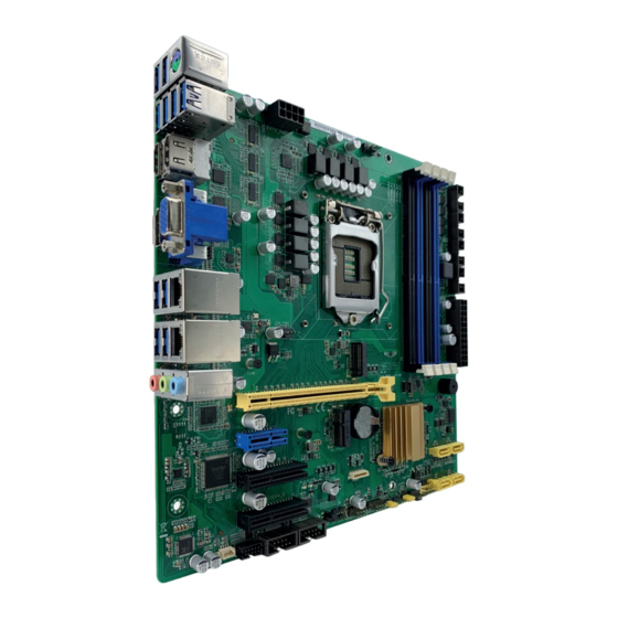
Page 10: Motherboard Layout
Motherboard layout NOTE: Place four screws into the holes indicated by circles to secure the motherboard to the chassis. CAUTION! Do not overtighten the screws! Doing so can damage the motherboard. 9 10 11 17.0cm(6.7in) SATA6G_1 SATA6G_2 SATA6G_3 SATA6G_4 EATX_PWR1 COM1 F_PANEL COM_V1... - Page 11 Connectors/Jumpers/Slots Page 12VDC connector (4-pin EATX_PWR2) 2-18 CPU and chassis fan connectors (4-pin CPU_FAN, 4-pin CHA_FAN) 2-19 System panel connector (10-1 pin F_PANEL) 2-21 SATA 6.0Gb/s connectors (7-pin SATA6G_1~4) 2-19 DDR4 DIMM slots 2-11 Digital I/O connector (10-pin DIO) 2-22 Serial port connector (10-pin COM1) 2-22 COM1 operating mode selection jumpers (2-pin J1/J2/J3/J4)
-
Page 12: Screw Size
Screw size 2.3.1 Component side 167.01 164.21 170.18 163.45 168.02 159.23 167.64 152.64 152.18 147.59 143.15 131.26 118.75 117.92 109.75 92.73 83.84 75.71 67.44 57.14 66.30 51.82 58.69 56.25 45.45 42.10 46.10 32.00 38.71 31.05 30.04 29.34 23.94 27.36 11.00 16.09 10.54 16.03... -
Page 13: Solder Side
2.3.2 Solder side 170.18 165.10 165.10 164.21 156.87 153.95 92.94 92.94 81.86 81.86 62.96 52.96 42.96 33.02 10.16 0.00 Chapter 2: Motherboard information... -
Page 14: Central Processing Unit (Cpu)
Central Processing Unit (CPU) This motherboard comes with an Intel 8th/9th Generation (Coffee Lake S) Core™ ® i7 / i5 / i3, Pentium LGA 1151 socket processor. ® MIX-Q370D1 MIX-Q370D1 CPU socket LGA1151 IMPORTANT: Unplug all power cables before installing the CPU. CAUTION! •... -
Page 15: Installing The Cpu
2.4.1 Installing the CPU CAUTION! Ensure that you install the correct CPU designed for LGA1151 only. DO NOT install a CPU designed for LGA1155 and LGA1156 sockets on the LGA1151 socket. Chapter 2: Motherboard information... - Page 16 MIX-Q370D1...
-
Page 17: Cpu Heatsink And Fan Assembly Installation
2.4.2 CPU heatsink and fan assembly installation CAUTION! Apply the Thermal Interface Material to the CPU heatsink and CPU before you install the heatsink and fan if necessary. To install the CPU heatsink and fan assembly Chapter 2: Motherboard information... - Page 18 To uninstall the CPU heatsink and fan assembly MIX-Q370D1 2-10...
-
Page 19: System Memory
System memory This motherboard comes with two Double Data Rate 4 (DDR4) Small Outline Dual Inline Memory Modules (SO-DIMM) sockets.The figure illustrates the location of the DDR4 DIMM sockets: DIMM_B1 DIMM_A1 MIX-Q370D1 MIX-Q370D1 260-pin DDR4 DIMM sockets NOTE: Use the DIMM_A1 slot when inserting only one SO-DIMM. Installing a DIMM To install a DIMM To remove a DIMM Chapter 2: Motherboard information... -
Page 20: Jumpers
Jumpers Clear RTC RAM (3-pin CLRTC1) This jumper allows you to clear the Real Time Clock (RTC) RAM in CMOS. You can clear the CMOS memory of system setup parameters by erasing the CMOS RTC RAM data. The onboard button cell battery powers the RAM data in CMOS, which include system setup information such as system passwords. - Page 21 COM1 Ring/+5V/+12V selection jumper (6-pin COM1_V1) COM1_V1 Ring +12V (Default) MIX-Q370D1 MIX-Q370D1 COM1 Ring/+5V/+12V Selection Setting Pins +12V Ring (Default) COM1 operating mode selection jumpers (2-pin J1/J2/J3/J4) J1、J2、J3、J4 RS232 (Default) RS485/RS422 with terminator MIX-Q370D1 MIX-Q370D1 COM1 operating mode selection (J1、J2、J3、J4) Setting Pins RS232...
- Page 22 AT/ATX mode selection (3-pin AT_ATX) AT_ATX ATX mode AT mode (Default) MIX-Q370D1 MIX-Q370D1 AT/ATX mode selection Pins ATX mode (Default) AT mode Chassis intrusion jumper (4-1 pin CHASSIS) This connector is for a chassis-mounted intrusion detection sensor or switch. Connect one end of the chassis intrusion sensor or switch cable to this connector.
- Page 23 LVDS panel voltage selection (3-pin LJ1) (Default) MIX-Q370D1 MIX-Q370D1 LVDS panel voltage selection Setting Pins +3.3V (Default) Inverter voltage selection (3-pin J2) +12V (Default) MIX-Q370D1 MIX-Q370D1 Inverter voltage selection Setting Pins 5V (Default) Inverter backlight control mode selection (3-pin LJ3) DC CTL PWM CTL (Default)
-
Page 24: Onboard Leds
Onboard LEDs Standby Power LED The motherboard comes with a standby power LED that lights up to indicate that the system is ON, in sleep mode, or in soft-off mode. This is a reminder that you should shut down the system and unplug the power cable before removing or plugging in any motherboard component. -
Page 25: Connectors
Connectors 2.8.1 Rear panel connectors DC power connector. Insert the power adapter into this port. USB 3.2 Gen 2 ports. These 9-pin Universal Serial Bus (USB) ports connect to USB 3.2 Gen 2 devices. NOTES: • USB 3.2 Gen 2 devices can only be used for data storage. •... -
Page 26: Internal Connectors
2.8.2 Internal connectors Internal power connectors (4-pin EATX_PWR2) This connector is for an EATX power supply plug. The power supply plug is designed to fit this connector in only one orientation. Find the proper orientation and push down firmly until the connector completely fits. EATX_PWR2 PIN 1 MIX-Q370D1 MIX-Q370D1 1 x 4-pin (2x2) internal power connector IMPORTANT: • For a fully configured system, we recommend that you use a power supply unit (PSU) that complies with ATX 12V Specification 2.0 (or later version). • We recommend that you use a PSU with higher power output when configuring a system with more power-consuming devices. The system may become unstable or may not boot up if the power is inadequate. - Page 27 Chassis / CPU fan connectors (4-pin CHA_FAN1, 4-pin CPU_FAN1) Connect the fan cables to the fan connectors on the motherboard, ensuring that the black wire of each cable matches the ground pin of the connector. CHA_FAN1 CPU_FAN1 MIX-Q370D1 MIX-Q370D1 Fan connectors CAUTION: Do not forget to connect the fan cables to the fan connectors.
- Page 28 USB 2.0 connectors (10-pin USB56, USB78 and USB910) These USB connectors comply with USB 2.0 specifications. USB56 USB78 USB910 PIN 1 PIN 1 PIN 1 MIX-Q370D1 MIX-Q370D1 USB2.0 connectors Never connect a 1394 cable to the USB connector. Doing so will damage the motherboard. BIOS programmable connector (8-pin SPI_1) Use this connector to flash the BIOS ROM.
- Page 29 System panel connectors (10-1 pin F_PANEL) This connector supports several chassis-mounted functions. F_PANEL +PWR LED- PWR_BTN PIN 1 +HDD_LED- RESET MIX-Q370D1 MIX-Q370D1 System panel connector • System power LED (2-pin PWR_LED) This 2-pin connector is for the system power LED. Connect the chassis power LED cable to this connector.
- Page 30 Serial port connector (10-pin COM1) This connector is for serial (COM) ports. Connect the serial port module cable to this connector, then install the module to a slot opening at the back of the system chassis. COM1 PIN 1 MIX-Q370D1 MIX-Q370D1 Serial port connector NOTE: The COM module is purchased separately.
- Page 31 10. M.2 E-Key and M-Key slots These sockets allow you to install an M.2 (NGFF) module. M.2(SOCKET3) M.2_TYPE_E1 2230 M.2_TYPE_M1(BOTTOM) 2280 MIX-Q370D1 MIX-Q370D1 M.2(SOCKET3)s NOTES: • The M.2 SSD module is purchased separately. • The M.2 E-key slot supports type 2230 PCIe/USB Wi-Fi module. •...
- Page 32 12. LVDS connector (40-pin LVDS) This connector is for an LCD monitor that supports Low-Voltage Differential Signaling (LVDS) interface. LVDS PIN 40 SPD1 +BLVCC +BLVCC +BLVCC LVDS1_CLK- LVDS1_CLK+ VCON INV_ENABKL SPC1 LVDS0_CLK- LVDS0_CLK+ +V_PANEL +V_PANEL +V_PANEL LVDS1_D0- LVDS1_D0+ LVDS1_D1- LVDS1_D1+ LVDS1_D2- LVDS1_D2+ LVDS1_D3-...
- Page 33 14. Embedded DisplayPort connector (40-pin eDP1) This connector is for an internal embedded DisplayPort connection. EDP1(BOTTOM) PIN 1 eDP_TXN3_C eDP_TXP3_C eDP_TXN2_C eDP_TXP2_C eDP_TXN1_C eDP_TXP1_C eDP_TXN0_C eDP_TXP0_C eDP_AUXP_C eDP_AUXN_C +V_PANEL +V_PANEL +V_PANEL +V_PANEL eDP_HPD_RRR BKLTEN_R BKLTCTL_R +BLVCC +BLVCC +BLVCC +BLVCC PIN 40 MIX-Q370D1 MIX-Q370D1 Embedded Display Port 15.
- Page 34 16. DMIC connector (5-1 pin DMIC) The DMIC connector is for connecting the digital microphone module used in All-in-One chassis. DMIC MIX-Q370D1 PIN 1 MIX-Q370D1 DMIC connector 17. Front panel audio connector (10-1 pin AAFP) This connector is for a chassis-mounted front panel audio I/O module that supports HD Audio audio standard.
-
Page 35: Chapter 3: Bios Setup
Chapter 3 BIOS setup BIOS setup Use the BIOS Setup to update the BIOS or configure settings. The BIOS screens include navigation keys and help to guide you in using the BIOS Setup program. Entering BIOS Setup at startup To enter BIOS Setup at startup: Press <Delete> during the Power-On Self Test (POST). If you do not press <Delete>, POST continues with its routine. Entering BIOS Setup after POST To enter BIOS Setup after POST: Press <Ctrl>+<Alt>+<Del>... -
Page 36: Main Menu
Menu bar The menu bar on top of the screen has the following main items: Main For changing the basic system configuration. Advanced For changing the advanced system settings. Chipset For viewing and changing chipset settings. Security For setting up BIOS security settings. Boot For changing the system boot configuration. Save &... -
Page 37: Cpu Configuration
3.3.1 CPU Configuration The items in this menu show CPU-related information the BIOS automatically detects. The items shown in the submenu may be different depending on the type of CPU installed. Hyper-threading [Enabled] The Intel Hyper-Threading Technology allows a hyper-threading processor to appear as two logical processors to the operating system, allowing the operating system to schedule two threads or processes simultaneously. -
Page 38: Sata Configuration
TPM2.0 UEFI Spec Version [TCG_2] Allows you to select the TCG2 spec version support. [TCG_1_2] Compatible mode for Windows 8 / Windows ® ® [TCG_2] Newer TCG2 protocol and event format for Windows 10 or ® later. Physical Presence Spec Version [1.3] Allows you to select which TCG Physical Presence Interface Specification Version is supported by the OS. Configuration options: [1.2] [1.3] Device Select [Auto]... -
Page 39: Hardware Monitor
[Auto] Allows the system to detect the presence of USB devices at startup. If detected, the USB controller legacy mode is enabled. If no USB device is detected, the legacy USB support is disabled. XHCI Hand-off [Enabled] [Enabled] Enables the support for operating systems without an XHCI hand-off feature. - Page 40 Fan Count Step Down [1] Input value range: [0~15] Fan Out Step Up Time [10] Sets the amount of time Fan Out takes to increase its value by one step. Input value range: [0~255] Fan Out Step Down Time [10] Sets the amount of time Fan Out takes to decrease its value by one step in intervals of 0.1 seconds.
-
Page 41: Sio Configuration
Fan Out Step Down Time [10] Determines the amount of time Fan Out takes to decrease its value by one step in intervals of 0.1 seconds. Input value range: [0~255] 3.3.6 SIO Configuration The items in this menu allow you to configure Super IO settings. [*Active*] Serial Port Use this device [Enabled] Allows you to enable or disable this logical device. Configuration options: [Enabled] [Disabled] The following two items appear only when you set Use this device to... -
Page 42: Digital Io Port Configuration
The following items appear when you set Power Mode to [ATX Type]. Restore AC Power Loss [Last State] [Last State] The system goes into either off or on state, whatever the system state was. [Always On] The system goes into on state after an AC power loss. [Always Off] The system goes into off state after an AC power loss. -
Page 43: Chipset Menu
Chipset menu The Chipset menu items allow you to change configuration options for the North Bridge and South Bridge. 3.4.1 System Agent (SA) Configuration MAX TOLUD [Dynamic] Allows you to select the maximum memory size of TOLUD (Top of Low Usable DRAM). Configuration options: [Dynamic] [1 GB] [1.25 GB] [1.5 GB] [1.75 GB] [2 GB] [2.25 GB] [2.5 GB] [2.75 GB] [3 GB] [3.25 GB] [3.5 GB] Primary Display [Auto] Allows you to decide which graphics controller to use as the primary boot device. -
Page 44: Security Menu
Security menu The Security menu items allow you to change the system security settings. 3.5.1 Administrator Password If you have set an administrator password, we recommend that you enter the administrator password for accessing the system. Otherwise, you might be able to see or change only selected fields in the BIOS setup program. -
Page 45: Boot Menu
<Enter>. Confirm the password when prompted. To clear the user password, follow the same steps as in changing a user assword, but press <Enter> when prompted to create/confirm the password. After you clear the password, the User Password item on top of the screen shows Not Installed. Boot menu The Boot menu items allow you to change the system boot options. 3.6.1 Boot Configuration Quiet Boot [Enabled]... - Page 46 MIX-Q370D1 3-12...
-
Page 47: Appendix
Appendix Notices Federal Communications Commission Statement This device complies with Part 15 of the FCC Rules. Operation is subject to the following two conditions: • This device may not cause harmful interference. • This device must accept any interference received including interference that may cause undesired operation. - Page 48 電子電氣產品有害物質限制使用標識要求:圖中之數字為產品之環保 使用期限。僅指電子電氣產品中含有的有害物質不致發生外洩或突變 從而對環境造成污染或對人身、財產造成嚴重損害的期限。 有害物質 部件名稱 鉛 汞 鎘 六價鉻 多溴聯 多溴二苯 (Pb) (Hg) (Cd) (Cr(VI)) 苯(PBB) 醚(PBDE) 印刷電路板及其 × ○ ○ ○ ○ ○ 電子組件 外殼 × ○ ○ ○ ○ ○ 電源適配器 × ○ ○ ○ ○ ○ 外部信號連接頭 ×...
Need help?
Do you have a question about the MIX-Q370D1-A12 and is the answer not in the manual?
Questions and answers