Table of Contents
Advertisement
Advertisement
Table of Contents

Related Manuals for Lockly Vision


Summary of Contents for Lockly Vision
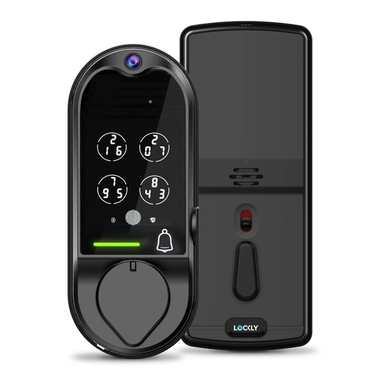
- Page 1 VISION ™ INSTALLATION GUIDE DEADBOLT EDITION...
- Page 2 Go to lockly.com/pages/installation to watch a video version of this installation guide. Download the BILT app in the Apple or Google Play store for step-by-step interactive 3-D walk-through installation instructions.
- Page 3 Welcome! This guide will walk you through step-by-step how to install and get your Lockly Vision up and running. Installation generally takes less than 30 minutes. If you have any questions please reference our online support at: Lockly.com/support or call (669) 500-8835 for help.
- Page 4 Preparation To complete the installation you will need: Flathead Screwdriver Tape measure or ruler Phillips Screwdriver Prepare door: remove existing deadbolt or use provided template to bore new holes. 2-⅜" (60mm) 2-¾" (70mm) 1-⅜" (35mm) Cross-bore to 2" (50mm) 2-⅛" (54mm) 1"...
- Page 5 Step 1 ADJUST DEADBOLT AND INSTALL Deadbolt slot must align to the center of the door hole. Adjust as shown if needed. 2-3/4" (70mm) or 2-3/8” (60mm) The deadbolt comes set to 2-3/4" (70mm). Adjust length to 2-3/8” (60mm) if necessary. (wear gloves to protect from possible pinching).
- Page 6 Step 1 ADJUST DEADBOLT AND INSTALL continued Extend the deadbolt by inserting a Insert the deadbolt into mortise flush with flat-head screwdriver into the slot and door edge, make sure that the right side is turning clockwise. up and the slot is in the vertical position. Secure with 2 screws.
- Page 7 Step 2 INSTALLING EXTERIOR ASSEMBLY (B) Check the exterior assembly (B) align- ment to door hole and deadbolt before peeling off film on adhesive strips. Peel film from adhesive strips and make sure torque blade is in the vertical position with the deadbolt extended.
- Page 8 Step 3 INSTALLING INTERIOR ASSEMBLY (G) 1: Check interior mounting plate (K) 2: Align and secure mounting plate with alignment to your door hole before adhesive strips. Guide connection cables securing with adhesive strips. through the hole and secure to the lower left notched hole.
- Page 9 (P) and (Q) with each other as much as possible. TIP: Lockly offers both brown and black sensor covers that can be ordered through our customer care hot line: (669) 500-8835 or by email: help@lockly.com. Removal of Sensor (optional) There may be circumstances where the sensor cannot be installed because of molding/door limitations or is not aesthetically desirable.
- Page 10 Step 4 PREPARING DOOR SENSORS FOR INSTALLATION continued When installing the door sensors, make sure the arrow on the wired sensor (P) aligns to the arrow of the sensor magnet (Q) as close as possible. 3/4" (20mm) 2-3/8" (60mm) Foam pad The sensors need to be as close to level as possible.
- Page 11 Step 4 PREPARING DOOR SENSORS FOR INSTALLATION continued The interior assembly comes with the For left swing doors, re-route the door pre-installed wired door sensor setup for a sensor wire through the side channel. right swing doors with 2 ¾" (70mm) backset*. Pull the foam pad then re-insert to secure the wire.
- Page 12 Step 5 INSTALLING THE INTERIOR ASSEMBLY (G) Plug the larger cable coming through mounting plate (D) into the interior assembly (G) as shown. Tuck cable under eyelet hooks and route to the right on interior assembly (G). Connect screw tightly by hand as shown.
- Page 13 Step 5 INSTALLING THE INTERIOR ASSEMBLY (G) continued Torque Blade Thumb turn shaft Align torque blade with thumb turn shaft, make sure both are in the vertical position. Before placing the interior Place the interior assembly Secure the interior assembly assembly onto the mount- against the mounting plate to mount platedoor with...
- Page 14 Step 6 INSTALLING BATTERIES IMPORTANT Install batteries 5-8 only after self-check is complete PRESS & HOLD 1: With door open and deadbolt fully extended, place ribbon inside compartment and insert 3 batteries only (hold on inserting the 4th) in bottom row (note correct -/+ polarity). 2: Press and HOLD the program button, continue to hold and install the 4th battery.
- Page 15 Step 6 INSTALLING BATTERIES 3: Once self-check completes ensure the lock operates smoothly by manually locking and unlocking the door using the thumb turn on the interior assembly. The deadbolt should operate smoothly without any interference or binding. If necessary, repeat step 2 and ensure that (a) the deadbolt was extended and (b) the torque blade was inserted vertically while the deadbolt was extended.
- Page 16 Step 7 INSTALLING THE DOORS SENSOR Make sure you have prepared the door sensors for installation, see step 4 LOCK SENSOR (P) Install on the interior side only. If necessary, trim tab from sensor (P) for doors with 2-3/8" (60mm) backset. Clean surface of door and doorframe, remove film from adhesive, attach and secure close to door edge as shown.
- Page 17 1 or 2 of the included adhesive foam pads. Once satisfied both sensors are as level as possible, remove film from adhesive and install with arrows aligned to each other with less than a 3/4" gap between each sensor. NOTE: When properly installed, the Lockly logo blinks red when door opens and closes.
- Page 18 Step 8 INSTALLING STRIKE PLATE Use the supplied door strike or use your existing as long as deadbolt operates smoothly without binding or catching. K(2X) IMPORTANT: because doors and frames vary in design it may be necessary to make slight adjustments to your strike plate and/or dust box in order to ensure smooth deadbolt operation.
- Page 19 PAIRING VISION CONNECT WITH LOCK To enable video doorbell, live monitoring and voice control with Google Assistant or Amazon Alexa, you will need to setup the included Vision Connect WI-Fi hub and pair it with the Lockly Vision deadbolt smart lock + video doorbell.
- Page 20 Additionally, you'll need the Activation Card with unique pre-paired QR code to AUTHENTIC LOCKLY PRODUCT | DESIGNED IN USA | CARD IS PRINTED WITH A SPECIFIC PATTERN your lock. The card is located in the packaging that your lock came in. This...
- Page 21 APP SET UP continued Set up an account by registering your Lockly Vision in the Lockly app. Registration is also mandatory to activate your locks warranty. After successful registration, select "add a new device" (you can also get to this from the menu in the top left), select Vision, and follow the step-by-step on screen instructions.
- Page 22 LOCATION GUIDELINES continued The Vision Connect Hub connects directly to your Wi-Fi router using the provided LAN cable. Choose an appropriate location for the hub for optimum performance (see below). For optimum connectivity, it is recommended that the hub be no further away from the lock than 100 feet, placed 3 feet (1 meter) off the ground.
- Page 23 Wait 2 minutes for hub to self calibrate. USB power adapter into outlet. Once LEDs turn RED and blink yellow. Vision Connect is now ready to connect to your iOS or Android device. See troubleshooting on next page if LEDs do not meet the described conditions.
- Page 24 PAIR VISION LOCK TO APP continued Launch the Lockly App and select "add a new device", then select Vision. You will be prompted to scan the QR code from the Activation Card or Vision Connect Hub (located at the bottom).
- Page 25 Blue slow blinking Update Successful Blue ON Blinking from red to blue Update has failed *Power interruption during firmware update may damage the Vision Connect hub. Do not interrupt or turn the power off while firmware update is in progress.
- Page 26 Amazon Alexa or action for Google Assistant. TIP: In Google Home and/or Amazon Alexa apps, add the “Lockly” skill for Alexa or action for Google Assistant, then follow on screen instructions. See full list of commands, help videos, or troubleshooting your Lockly Vision at https://lockly.com/help...
- Page 27 FCC Radiation Exposure Statement Vision Connect complies with FCC radiation exposure limits set forth for an uncontrolled environment. It should be installed and operated with minimum distance 20cm between the radiator & your body.
- Page 28 Sensor Magnet Vision Connect LAN Cable Power Plug TF Card Activation Card AUTHENTIC LOCKLY PRODUCT | DESIGNED IN USA | CARD IS PRINTED WITH A SPECIFIC PATTERN LOCK SERIAL PGDxxxxxxxxxx ACTIVATION CODE xxxxxxxx SCAN & SAVE Lockly Vision can be fitted for both right swing doors and left swing doors.
- Page 29 Connect with us @meetlockly | #lockly...
- Page 30 Reference installation parts overview foldout.
- Page 31 VISION ™ We’re here to help! Email: help@lockly.com lockly.com/help For the most up to date version of this guide please visit: lockly.com/help IMPGD1128FPW20200713...
Need help?
Do you have a question about the Vision and is the answer not in the manual?
Questions and answers
I just bought a house that has a Lockly deadbolt lock. The tenant left with the vision connect so I cannot reprogram it. HELP!
The provided context does not contain information on reprogramming a Lockly Vision deadbolt lock without the Vision Connect.
This answer is automatically generated