Table of Contents
Advertisement
Available languages
Available languages
CENTRALE DI COMANDO
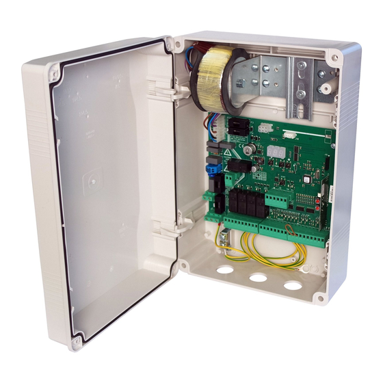
CONTROL UNIT
CENTRALE DE COMMANDE
STEUERZENTRALE
CENTRAL DE MANDO
Attenzione! Leggere attentamente le "Avvertenze" all'interno! Caution! Read "Warnings" inside carefully! Attention! Veuillez lire attentivement les Avertissements qui se trouvent à l'intérieur!
Achtung! Bitte lesen Sie aufmerksam die „Hinweise" im Inneren! ¡Atención¡ Leer atentamente las "Advertencias" en el interior! Let op! Lees de "Waarschuwingen" aan de binnenkant zorgvuldig!
Advertisement
Chapters
Table of Contents

Related Manuals for BFT CSB Xtreme


Summary of Contents for BFT CSB Xtreme
-
Page 1: J9 Signaux Inverter Type
CENTRALE DI COMANDO CONTROL UNIT CENTRALE DE COMMANDE STEUERZENTRALE CENTRAL DE MANDO Attenzione! Leggere attentamente le “Avvertenze” all’interno! Caution! Read “Warnings” inside carefully! Attention! Veuillez lire attentivement les Avertissements qui se trouvent à l’intérieur! Achtung! Bitte lesen Sie aufmerksam die „Hinweise“ im Inneren! ¡Atención¡ Leer atentamente las “Advertencias” en el interior! Let op! Lees de “Waarschuwingen” aan de binnenkant zorgvuldig! -
Page 2: Table Of Contents
1. INTRODUZIONE 2. CARATTERISTICHE PRINCIPALI 3. CARATTERISTICHE TECNICHE 4. SICUREZZA DELL’INSTALLAZIONE 5. OPERAZIONI PRELIMINARI 6. COLLEGAMENTI E FUNZIONALITA’ DI INGRESSI E USCITE 6.1 J1 ALIMENTAZIONE CENTRALE DI COMANDO 6.2 J4 USCITA LAMPEGGIANTE 6.3 J5 ALIMENTAZIONE ACCESSORI/USCITE 6.4 J6 ENCODER/INGRESSI 6.5 J7 INGRESSI/ANTENNA 6.6 J8 CONNETTORE ALIMENTATORE LUCI 6.7 J10 CONNETTORE ESPANSIONE 6.8 J12 CONNETTORE PROGRAMMATORE RADIO... -
Page 3: Introduzione
Centrale di comando 1. INTRODUZIONE La centrale di comando è stata sviluppata per gestire barriere automatiche. = Collegamenti elettrici già predisposti in fabbrica. 2. CARATTERISTICHE PRINCIPALI - Logica a microprocessore - Display 3 digit per lo stato del sistema e programmazione - LEDs di visualizzazione dello stato degli ingressi/uscite - Fino a 4 uscite confi gurabili - Ricevente radio 433,92MHz 2 canali, 2 048 codici... -
Page 4: Caratteristiche Tecniche
Centrale di comando 3. CARATTERISTICHE TECNICHE - Alimentazione..........230Vac ±10%, 50/60Hz (a richiesta115Vac) - Uscita lampeggiante................230Vac; 40W max - Uscita accessori.....................24Vac; 1A max 4. SICUREZZA DELL’INSTALLAZIONE Affi nché si raggiunga il grado di sicurezza richiesto dalla normativa vigente, leggere attentamente le seguenti prescrizioni. 1) Realizzare tutti i collegamenti in morsettiera leggendo attentamente le indicazioni riportate in questo manuale ed osservando le norme generali e di buona tecnica che regolano l’esecuzione degli impianti elettrici. -
Page 5: J6 Encoder/Ingressi
Centrale di comando OUT4 Uscita programmabile di relé a contatto pulito 500mA max, 24Vac/dc (parametro - 2°liv) OUT5/CH2 RX Uscita programmabile N.O. del 2° canale ricevitore radio integrato (parametro - 2°liv) ENCODER/INGRESSI ENCODER Viene fornito già cablato e collaudato. Il dispositivo interviene nella sola fase di chiusura quando la barra urta un ostacolo. -
Page 6: J8 Connettore Alimentatore Luci
Centrale di comando CONNETTORE ALIMENTATORE LUCI CONNETTORE ESPANSIONE Togliere l’alimentazione prima di inserire o rimuovere l’alimentatore luci e/o il modulo di espansione B EBA RS 485 LINK CONNETTORE PROGRAMMATORE RADIO 7. COLLEGAMENTI INVERTER MOTORE ALIMENTAZIONE INVERTER (tutti i tipi) CENTRALE DI COMANDO 230Vac 50/60Hz con protezione interna a fusibile. -
Page 7: J9 Segnali Inverter Tipo
Centrale di comando SEGNALI INVERTER TIPO 2 INVERTER TIPO 2 (J2) CENTRALE DI COMANDO (J9) Grigio Rosa GND/COM: Verde FWD: Giallo REV: Bianco (J6) +V ENC: Marrone GND ENC SIG. ENC +V ENC ENCODER CABLE 8. DISPLAY All’accensione viene presentata la versione scheda “Htr”, poi la versione FW X.Y.Z. e, infi ne, lo stato o il codice di errore. Il codice di stato o di errore viene sempre visualizzato tranne nel menù... -
Page 8: Programmazione
Centrale di comando 9. PROGRAMMAZIONE 9.1 FUNZIONALITÁ DI BASE Per accedere alla programmazione premere il pulsante F per 2 secondi. La programmazione è divisa in 4 livelli. Per passare al livello successivo mantenere premuto il tasto F e agire sul tasto + (Sequenza 1-2-3-1..). Selezionato il livello desiderato, premendo il pulsante F vengono visualizzate sul display le funzioni disponibili in ordine successivo;... -
Page 9: Programmazione Di 1° Livello
Centrale di comando 9.2 PROGRAMMAZIONE DI 1° LIVELLO Nella tabella seguente vengono presentate le funzioni di 1° livello e i singoli parametri impostabili. = valore del parametro impostato in fase di installazione: da indicare nel caso si = valore di DEFAULT impostato in azienda. modifi chi il valore di DEFAULT. - Page 10 Centrale di comando Funzione Valori impostabili : Spento : Rosso : Verde : Blu : Rosa : Rosa scuro : Orchidea : Viola : Magenta : Blu/Viola : Ciano : Blu chiaro = Colore cappello luci a barra aperta ...
-
Page 11: Programmazione Di 2° Livello
Centrale di comando 9.3 PROGRAMMAZIONE DI 2° LIVELLO Nella tabella seguente vengono presentate le funzioni di 2° livello e i singoli parametri impostabili. = valore del parametro impostato in fase di installazione: da indicare = valore di DEFAULT impostato in azienda. nel caso si modifi chi il valore di DEFAULT. -
Page 12: Programmazione Di 3° Livello
Centrale di comando · : UPS TIPO UPS UPS ad onda quadra Rilevatore interno, ingresso UPS non collegato UPS ad onda sinusoidale pura o quasi sinusoidale con uscita Collegare il segnale di assenza rete all’ingresso UPS segnalazione di assenza rete UPS ad onda sinusoidale pura senza uscita segnalazione di Utilizzare relè... -
Page 13: Programmazione Di 4° Livello
Centrale di comando 9.5 PROGRAMMAZIONE DI 4° LIVELLO Nella tabella seguente vengono presentate le funzioni di 4° livello e i singoli parametri impostabili. = valore del parametro impostato in fase di installazione: da = valore di DEFAULT impostato in azienda. indicare nel caso si modifi chi il valore di DEFAULT. -
Page 14: Ricevente Radio
Centrale di comando 11. RICEVENTE RADIO 11.1 DATI TECNICI RICEVENTE - N° max radiotrasmettitori memorizzabili: 2 048 - Frequenza: 433.92MHz - Codice a mezzo: Algoritmo rolling-code - N°combinazioni: 4 miliardi 11.2 FUNZIONALITÁ CANALE RADIO Canale radio 1: Invia il comando di START Canale radio 2: Chiude il contatto a relé... -
Page 15: Tabella A
- 15 -... -
Page 16: Entrata Controllata Ed Uscita Automatica
Centrale di comando 13. ENTRATA CONTROLLATA ED USCITA AUTOMATICA Questa soluzione è consigliata quando si desidera accedere ad un’area riservata in entrambi i sensi di marcia. In entrata il transito è consentito mediante un comando di riconoscimento, mentre l’uscita è automatica. ENTRATA Il dispositivo di riconoscimento abilita l’apertura della barriera. -
Page 17: Risoluzione Dei Problemi
Centrale di comando 14. RISOLUZIONE DEI PROBLEMI - In caso di qualsiasi malfunzionamento verifi care che sia stato selezionata la barriera corretta (paragrafo 5) - Doppio lampeggio su luci barra: indica la richiesta manutenzione programmata. Verifi care i parametri -2°liv., -2°liv., -2°liv. - Dispersione di corrente verso terra: l’inverter tipo 1 dispone di un fi ltro di rumore ad alta attenuazione ed è... - Page 18 Contents 1. INTRODUCTION 2. MAIN CHARACTERISTICS 3. TECHNICAL SPECIFICATIONS 4. INSTALLATION SAFETY 5. PRELIMINARY OPERATIONS 6. INPUT AND OUTPUT FUNCTIONALITY AND CONNECTIONS 6.1 J1 CONTROL UNIT POWER SUPPLY 6.2 J4 FLASHING LIGHT OUTPUT 6.3 J5 OUTPUTS/ACCESSORIES POWER SUPPLY 6.4 J6 ENCODER/INPUTS 6.5 J7 INPUTS/ANTENNA 6.6 J8 BOOM LIGHTS CONNECTOR 6.7 J10...
-
Page 19: Introduction
Control unit 1. INTRODUCTION The control unit has been developed to control automatic single-phase barriers with inverter-driven three-phase motor. = Electrical connections confi gured at the factory. 2. MAIN CHARACTERISTICS - Microprocessor logic - 3-digit display for programming and system status - LEDs displaying inputs/outputs status - Up to 4 confi gurable outputs - Integrated radio receiver 433.92MHz, 2 channels, 2 048 codes... -
Page 20: Technical Specifications
Control unit 3. TECHNICAL SPECIFICATIONS - Power supply:............230Vac ±10%, 50/60Hz (115Vac on request) - Flashing light output:....................230Vac; 40W max - Accessory output:...................24Vac; 24W - 1A max 4. INSTALLATION SAFETY In order to reach the level of safety required by current regulations, follow these prescriptions carefully. 1) Make all connections in the terminal block after carefully reading the instructions given in this manual and observing the general rules and technical standards concerning electrical systems installations. -
Page 21: J6 Encoder/Inputs
Control unit OUT4 Programmable dry relay output, max. 500mA 24 Vac/dc (parameter - level 2) OUT5/CH2 RX Programmable dry relay output, max. 500mA 24 Vac/dc or N.O. output of the 2nd radio receiver channel (parameter - level 2) ENCODER/INPUTS ENCODER Supplied already wired. -
Page 22: J8 Boom Lights Connector
Control unit BOOM LIGHTS CONNECTOR EXPANSION CONNECTOR B EBA RS 485 LINK RADIO PROGRAMMER CONNECTOR 7. INVERTER CONNECTIONS MOTOR INVERTER POWER SUPPLY (all types) CONTROL UNIT 230Vac 50/60Hz with internal protection and fuse. INVERTER TYPE 1 INVERTER SIGNALS TYPE 1 INVERTER CC: Brown F: Yellow R: White... -
Page 23: J9 Type 2 Inverter Signals
Control unit TYPE 2 INVERTER SIGNALS TYPE 2 INVERTER (J2) CONTROL UNIT (J9) Gray Pink GND/COM: Green FWD: Yellow REV: White (J6) +V ENC: Brown GND ENC SIG. ENC +V ENC ENCODER CABLE 8. DISPLAY At power-on is shown the board version “Htr”, after the FW release X.Y.Z and then the status or error code. The status or error code is always displayed except in programming menu or when is present a blocking error. -
Page 24: Programming
Control unit 9. PROGRAMMING 9.1 BASIC FUNCTIONS To access programming, press button F for 2 seconds. Programming is divided into 4 levels. To go to the next level keep key F pressed and press the + key (Sequence 1-2-3-1..). After selecting the desidered level, press push button F to display the functions available in consecutive order. Each F pression corre- sponds to a function (... -
Page 25: 1St Programming Level
Control unit LEVEL PROGRAMMING The following table gives the 1st level functions and the single settable parameters. = parameter value set during installation: must be indicated if = DEFAULT value set in factory. DEFAULT value is modifi ed. Function Settable data : Hold-to-run Selects the functio- ... - Page 26 Control unit : Off : Red : Green : Blue : Pink : Dark pink Cap light when opened boom : Orchid : Purple : Magenta : Blue/Purple : Cyan : Light blue : Turquoise : Sky Blue : Aquamarine : Light green : Olive green...
-
Page 27: 2Nd Programming Level
Control unit LEVEL PROGRAMMING The following table gives the 2nd level functions and the single settable parameters. = parameter value set during installation: must be indicated if DEFAULT value is modifi ed. = DEFAULT value set in factory. Function Settable data ... -
Page 28: 3Rd Programming Level
Control unit · : UPS UPS TYPE Square-wave Internal detector, UPS input not connected UPS with sinusoidal or quasi-sinusoidal wave form, with Connect mains failure output to UPS input dedicated output for signaling the absence of power net Pure-sinusoidal wave UPS with dedicated output for signaling Use 230Vac relais, coil connected to mains supply, close contacts to UPS input the absence of power net ·... -
Page 29: 4Th Programming Level
Control unit : · Swinging boom sensor input N.C. swingin boom sensor not mounted or disabled automation stops immediately in case of swinging boom opened LEVEL PROGRAMMING The following table gives the 4th level functions and the single parameters. = parameter value set during installation: must be indicated = DEFAULT value set in factory. -
Page 30: Radio Receiver
Control unit 11. RADIO RECEIVER 11.1 RECEIVER TECHNICAL SPECIFICATIONS - Max. n° of radio transmitters that can be memorized: 2 048 - Frequency: 433.92MHz - Code by means of: Rolling-code algorithm - N° of combinations: 4 billions 11.2 RADIO CHANNEL FUNCTIONALITY Channel 1: Start command Channel 2:... - Page 31 - 31 -...
-
Page 32: Controlled Entry And Automatic Exit
Control unit 13. CONTROLLED ENTRY AND AUTOMATIC EXIT This solution is recommended when you want to enter a reserved area in both directions. To enter, transit is allowed by means of a reco- gnition command while exiting is automatic. ENTRY The recognition system enables bar- rier opening. -
Page 33: Troubleshooting Guide
Control unit 14. TROUBLESHOOTING GUIDE - In case of a malfunction, check if the correct barrier was selected (paragraph 5) - Dual fl ashing of the cover lights. Indicates that scheduled maintenance is required. Check the parameters -2ND level, -2ND level, -2ND level. - Leakage current to ground problem: the Inverter type 1 have a built-in high-attenuation noise fi lter and are grounded via a capacitor. - Page 34 1. AVANT-PROPOS 2. CARACTERISTIQUES PRINCIPALES 3. CARACTERISTIQUES TECHNIQUES 4. SECURITE DE L’INSTALLATION 5. OPÉRATIONS PRÉLIMINAIRES 6. CONNEXIONS ET DESCRIPTION DES ENTRÉES ET DES SORTIES 6.1 J1 ALIMENTATION CENTRALE DE COMMANDE 6.2 J4 SORTIE CLIGNOTANT 6.3 J5 ALIMENTATION ACCESSOIRES/SORTIES 6.4 J6 ENCODEUR/ENTRÉES 6.5 J7 ENTRÉES/ANTENNE 6.6 J8 CONNECTEUR ALIMENTATEUR LUMIÈRES 6.7 J10 CONNECTEUR EXPANSION...
-
Page 35: Avant-Propos
Centrale de commande 1. AVANT-PROPOS La centrale de commande a été élaborée pour gérer des barrières automatiques. = Branchements électriques déjà prédisposés en usine. 2. CARACTERISTIQUES PRINCIPALES - Logique à microprocesseur - Écran 3 chiff res pour l’état du système et la programmation - Diodes qui affi chent l’état des entrées - Jusqu’à... -
Page 36: Luci Cappello Maxima Ultra
Centrale de commande 3. CARACTERISTIQUES TECHNIQUES - Alimentation.....230Vac ±10%, 50/60Hz (115Vac a la démande nous consulter) - Sortie clignotant:.....................230Vac; 40W max - Sortie accessoires......................24Vac; 1A max 4. SECURITE DE L’INSTALLATION Pour atteindre le degré de sécurité requis par la législation en vigueur, lisez attentivement et suivez les prescriptions suivantes. Tous les branchements dans le bornier doivent être eff ectués après avoir lu attentivement les indications reportées dans ce mode d’emploi et en suivant les règles générales et de bonne technique qui règlent la réalisation des installations électriques. -
Page 37: J6 Encodeur/Entrées
Centrale de commande OUT4 Sortie programmable de relais à contact propre 500mA max, 24Vac/dc (paramètre - 2°niveau) OUT5/CH2 RX Sortie programmable N.O. du 2e canal récepteur radio intégré (paramètre - 2e niv.) ENCODEUR/ENTRÉES ENCODEUR Il est fourni déjà câblé et testé. Le dispositif intervient uniquement dans la phase de fermeture lorsque la barre rencontre un obstacle. -
Page 38: J8 Connecteur Alimentateur Lumières
Centrale de commande CONNECTEUR ALIMENTATEUR LUMIÈRES CONNECTEUR EXPANSION B EBA RS 485 LINK CONNECTEUR PROGRAMMATEUR RADIO 7. BRANCHEMENTS INVERTER MOTEUR ALIMENTATION INVERTER (toutes sortes) CENTRALE DE COMMANDE 230Vca 50/60Hz avec protection interne à fusible. INVERTER SIGNAUX ONDULEUR TYPE 1 INVERTER TYPE 1 CC: Marron F: Jaune R: Blanc... -
Page 39: Display
Centrale de commande SIGNAUX ONDULEUR TYPE 2 INVERTER TYPE 2 (J2) CENTRALE DE COMMANDE (J9) Gris Rose GND/COM: Vert FWD: Jaune REV: Blanc (J6) +V ENC: Marron GND ENC SIG. ENC +V ENC ENCODER CABLE 8. DISPLAY A l’allumage la version de carte Htr est présentée puis la version FW X Y Z et enfi n l’état ou le code d’erreur. Le code d’état ou d’erreur est toujours affi ché... -
Page 40: Programmation
Centrale de commande 9. PROGRAMMATION 9.1 FONCTIONS DE BASE Pour accéder à la programmation, appuyer sur le bouton F pendant 2 secondes. La programmation est subdivisée sur 3 niveaux. Pour passer au niveau suivant, maintenir enfoncée la touche F et intervenir sur la touche + (Séquence 1-2-3-1 …….). Une fois le niveau voulu sélectionné, en appuyant sur le bouton F, les fonctions disponibles s’affi chent dans l’ordre sur le moniteur ;... -
Page 41: Programmation De 1Er Niveau
Centrale de commande 1er NIVEAU 9.2 PROGRAMMATION DE Dans le tableau ci-dessous, fi gurent les fonctions de 1er niveau et les diff érents paramètres programmables. = valeur du paramètre défi nie en phase d’installation : à indiquer = valeur DEFAULT défi nie en usine. en cas de modifi cation de la valeur DEFAULT. - Page 42 Centrale de commande : Off : Rouge : Vert : Bleu : Rose : Rose foncé Cap lumière quand boom ouvert : Orchidée : Violet : Magenta : Bleu/Violet : Cyan : Bleu clair : Turquoise : Bleu ciel : Aigue-marine : Vert clair : Olive verte...
-
Page 43: Programmation De 2Er Niveau
Centrale de commande 9.3 PROGRAMMATION DE 2ème NIVEAU Dans le tableau ci-dessous, fi gurent les fonctions de 2ème niveau et les diff érents paramètres programmables. = valeur du paramètre défi nie en phase d’installation : à indiquer en = valeur DEFAULT défi nie en usine. cas de modifi cation de la valeur DEFAULT. -
Page 44: Programmation De 3Er Niveau
Centrale de commande · : ONDULEUR TYPE ONDULEUR ONDULEUR à onde carrée Détecteur interne, entrée ONDULEUR non reliée ONDULEUR à onde sinusoïdale pure ou presque sinusoïdale avec Relier le signal d’absence de réseau à l’entrée ONDULEUR sortie signalisation d’absence de réseau ONDULEUR à... -
Page 45: Programmation De 4Er Niveau
Centrale de commande : · Capteur entrée barre rupture capteur de barre rupture non monté ou déshabilité entrée N.C. blocage automation en cas de rupture de barre 4ème NIVEAU 9.5 PROGRAMMATION DE Dans le tableau ci-dessous, fi gurent les fonctions de 4ème niveau et les diff érents paramètres. = valeur du paramètre défi nie en phase d’installation : à... -
Page 46: Recepteur Radio
Centrale de commande 11. RECEPTEUR RADIO 11.1 DONNÉES TECHNIQUES RECEPTEUR - N° max radio-émetteurs mémorisables : 2 048 - Fréquence: 433.92MHz - Code à moyen: Algorithme rolling-queues - N°combinaisons: 4 milliards 11.2 FONCTION CANAL RADIO Canal 1: Commande de START Canal 2: Ferme le contact à... -
Page 48: Entrée Contrôlée Et Sortie Automatique
Centrale de commande 13. ENTRÉE CONTRÔLÉE ET SORTIE AUTOMATIQUE Cette solution est conseillée lorsque l’on souhaite accéder à une aire réservée dans les deux sens de marche. En entrée, le transit est permis en activant une commande de reconnaissance, tandis que la sortie est automatique. ENTREE Le dispositif de reconnaissance valide l’ouverture de la barrière. -
Page 49: Résolution Des Problèmes
Centrale de commande 14. RÉSOLUTION DES PROBLÈMES - En cas de dysfonctionnement quelconque, vérifi er que la barrière correcte a été sélectionnée (paragraphe 5) - Double clignotement sur les lumières de barre : cela indique la nécessité d’eff ectuer l’entretien programmé. Vérifi er les paramètres -2e niv., -2e niv., -2e niv. - Page 50 1. EINLEITUNG 2. HAUPTEIGENSCHAFTEN 3. TECHNISCHE EIGENSCHAFTEN 4. SICHERHEIT DER INSTALLATION 5. VORARBEITEN 6. ANSCHLUSS UND FUNKTION DER EIN- UND AUSGÄNGE 6.1 J1 STROMSPEISUNG ZENTRALE STEUEREINHEIT 6.2 J4 AUSGANG BLINKEND 6.3 J5 STROMSPEISUNG ZUBEHÖRTEILE/AUSGÄNGE 6.4 J6 ENCODER/EINGÄNGE 6.5 J7 EINGÄNGE/ANTENNE 6.6 J8 STECKER NETZTEIL LICHTER 6.7 J10 STECKER EXPANSION 6.8 J12 STECKER FUNKPROGRAMMIEREINHEIT...
-
Page 51: Einleitung
Steuerzentrale 1. EINLEITUNG Die zentrale Steuereinheit wurde entwickelt, um automatische Schranken zu überwachen. = Stromanschlüsse schon werkseitig vorgerüstet 2. HAUPTEIGENSCHAFTEN - Mikroprozessorgesteuerte Logik - 3-Digit-Display für den Zustand des Systems und Programmierung - Led zur Anzeige des Status der Eingänge - Bis zu 4 konfi gurierbare Ausgänge - Steckfunkempfänger 433,92MHz 2 Kanäle, 2048 codes - Stecker Funkprogrammiereinheit... -
Page 52: Technische Eigenschaften
Steuerzentrale 3. TECHNISCHE EIGENSCHAFTEN - Versorgung..........230Vac ±10%, 50/60Hz (auf Anfrage115Vac) - Blinker......................230Vac; 40W max - Zubehörausgang....................24Vac; 1A max 4. SICHERHEIT DER INSTALLATION Die nachstehenden Vorschriften sind aufmerksam zu lesen, damit der gesetzlich vorgeschriebene Schutzgrad erhalten wird. Alle Anschlüsse am Klemmenbrett sind unter Beachtung der in dem vorliegenden Handbuch enthaltenen Anleitungen und unter Anwendung der für die kunstgerechte Ausführung von elektrischen Anlagen erforderlichen Techniken zu realisieren. -
Page 53: J6 Encoder/Eingänge
Steuerzentrale OUT4 Programmierbarer, potentialfreier Relaisausgang 500mA max, 24Vac/dc (Parameter - 2. Ebene) OUT5/CH2 RX Programmierbarer N.O.-Ausgang des 2. integrierten Funkempfängerkanals (Parameter - 2. Ebene) ENCODER/EINGÄNGE ENCODER Wird schon verkabelt und abgenommen geliefert. Die Vorrichtung greift nur in der Schließphase ein, wenn die Schranke gegen ein Hindernis stößt. -
Page 54: J8 Stecker Netzteil Lichter
Steuerzentrale STECKER NETZTEIL LICHTER STECKER EXPANSION B EBA RS 485 LINK STECKER FUNKPROGRAMMIEREINHEIT 7. ANSCHLÜSSE INVERTER MOTOR SPEISUNG INVERTER (Alle Typ) ZENTRALE STEUEREINHEIT 230Vac 50/60Hz mit internem Sicherungsschutz. INVERTER SIGNALE INVERTER TYP 1 INVERTER TYP 1 CC: Braun F: Gelb R: Weiss ZENTRALE STEUEREINHEIT (J9) Grauen... -
Page 55: J9 Signale Inverter Typ2
Steuerzentrale SIGNALE INVERTER TYP 2 INVERTER TYP 2 (J2) ZENTRALE STEUEREINHEIT (J9) Grauen Rose GND/COM: Grün FWD: Gelb REV: Weiss (J6) +V ENC: Braun GND ENC SIG. ENC +V ENC ENCODER CABLE 8. DISPLAY Beim Einschalten wird die Version der Karte “Htr” angezeigt, dann die Version FW X.Y.Z. Und schließlich der Status oder der Fehlercode. Der Status- oder Fehlercode wird immer angezeigt, mit Ausnahme im Menü... -
Page 56: Programmierung
Steuerzentrale 9. ROGRAMMIERUNG 9.1 BASISBETRIEB Für den Zugang zur Programmierung die Taste F 2 Sekunden lang drücken. Die Programmierung ist in 3 Stufen unterteilt. Für den Übergang zur nächsten Stufe die Taste F gedrückt halten und die Taste + betätigen (Sequenz 1-2-3-1 ……) Nach Wahl der gewünschten Stufe werden nach Drücken der Taste F auf dem Display die verfügbaren Funktionen der Reihenfolge nach angezeigt;... -
Page 57: Programmierung 1. Stufe
Steuerzentrale 9.2 PROGRAMMIERUNG 1. STUFE In der nachfolgenden Tabelle sind die Funktionen der 1. Stufe und die einzelnen einstellbaren Parameter aufgeführt. = bei der Installation eingestellter Parameterwert: muss angege- = im Werk eingestellter STANDARD-Wert. ben werden, falls der STANDARD-Wert geändert wird. Aufgabe Einstellbare Parameter : Person anwesend... - Page 58 Steuerzentrale : Off : Rot : Grün : Blau : Rosa : Dunkelpink Kappenlicht bei geöff netem Ausleger : Orchidee : Lila : Magenta Farbe : Blau/Lila : Cyan : Hellblaue Farbe : Türkis : Himmelblaue Farbe : Aquamarin : Hellgrün : Olivgrün : Gelbgrün...
-
Page 59: Programmierung 2. Stufe
Steuerzentrale 9.3 PROGRAMMIERUNG 2. STUFE In der nachfolgenden Tabelle sind die Funktionen der 2. Stufe und die einzelnen einstellbaren Parameter aufgeführt. = bei der Installation eingestellter Parameterwert: muss angegeben = im Werk eingestellter STANDARD-Wert. werden, falls der STANDARD-Wert geändert wird. Aufgabe Einstellbare Parameter ... -
Page 60: Programmierung 3. Stufe
Steuerzentrale · : UPS UPS-TYP UPS mit Rechteckschwingung Internes Erfassungsgerät, UPS-Eingang nicht angeschlossen UPS mit Sinuswelle oder Quasi-Sinuswelle mit Signal-Ausgang Das Netzabwesenheitssignal an den Eingang UPS anschließen Netzausfall UPS mit reiner Sinuswelle ohne Ausgang Störungssignalisierung Das Relais 230 Vac mit Spule am Netz angeschlossen und Kontakte am Ein- gang UPS verwenden ·... -
Page 61: Programmierung 4. Stufe
Steuerzentrale N/A Kontrollierte Einfahrt und Automatische Ausfahrt (siehe Abschnitt 13) : · Sensor Eingang Bruch-Schranke Sensor Bruch-Schranke nicht montiert oder deaktiviert Eingang N.C. Sperre Automatisierung im Falle eines Bruchs-Schranke 9.5 PROGRAMMIERUNG 4. STUFE In der nachfolgenden Tabelle sind die Funktionen der 4. Stufe und die einzelnen einstellbaren Parameter aufgeführt. = bei der Installation eingestellter Parameterwert: muss angegeben = im Werk eingestellter STANDARD-Wert. -
Page 62: Steckfunkempfänger
Steuerzentrale 11. STECKFUNKEMPFÄNGER 11.1 TECHNISCHE DATEN EMPFÄNGER - Max. Anzahl der abspeicherbaren Funksteuerungen: 2 048 - Frequenz: 433.92MHz - Code mit: Rolling-Code-Algorhythmus - Anzahl Kombinationen: 4 Milliarden 11.2 FUNKTION FUNKKANAL Kanal 1: Sendet den Startbefehl Kanal 2: Schließt den Relaiskontakt im Klemmbrett J5 “CH2 RX” 11.3 ANTENNENINSTALLATION Verwenden Sie eine auf die Frequenz von 433MHz abgestimmte Anten-... -
Page 64: Kontrollierte Einfahrt Und Automatische Ausfahrt
Steuerzentrale 13. KONTROLLIERTE EINFAHRT UND AUTOMATISCHE AUSFAHRT Diese Lösung wird empfohlen, wenn die Zufahrt zu einem reservierten Bereich oder das Verlassen desselben, d.h. Einfahrt oder Ausfahrt, ermöglicht werden soll. Die Einfahrt wird durch ein Erkennungssignal zugelassen, während die Ausfahrt automatisch erfolgt. EINFAHRT Die Erkennungsvorrichtung gibt das Öff nen der Schranke frei. -
Page 65: Problembehebung
Steuerzentrale 14. PROBLEMBEHEBUNG - Im Falle einer mangelhaften Störung prüfen, ob die korrekte Schranke gewählt wurde (Abschnitt 5) - Doppeltes Blinken an Schrankenlichtern: Geplante Wartung erforderlich. Die Parameter -2. Ebene., -2. Ebene, -2. Ebene prüfen. - Erdschluss: Der Inverter Typ 1 verfügt über einen Geräuschfi lter mit hoher Dämpfung und ist mit einem Kondensator geerdet. Ein Schalter ermöglicht die Einschränkung des Erdschlusses. - Page 66 1. INTRODUCCIÓN 2. CARACTERÍSTICAS PRINCIPALES 3. CARACTERÍSTICAS TÉCNICAS 4. SEGURIDAD DE LA INSTALACIÓN 5. OPERACIONES PRELIMINARES 6. CONEXIONES Y FUNCIONES DE ENTRADAS Y SALIDAS 6.1 J1 ALIMENTACIÓN CENTRAL DE MANDO 6.2 J4 SALIDA PARPADEANTE 6.3 J5 ALIMENTACIÓN ACCESORIOS/SALIDAS 6.4 J6 ENCODER/ENTRADAS 6.5 J7 ENTRADAS/ANTENA 6.6 J8 CONECTOR ALIMENTADOR DE LUCES 6.7 J10 CONECTOR EXPANSIÓN...
-
Page 67: Introducción
Central de mando 1. INTRODUCCIÓN La central de mando ha sido diseñada para controlar barreras automáticas. = Conexión eléctrica ya predispuesta en fábrica. 2. CARACTERÍSTICAS PRINCIPALES - Lógica de control por microprocesador - Pantalla 3 dígitos para el estado del sistema y programación - Pilotos que muestran el estado de las entradas - Hasta 4 salidas confi gurables - Receptora radio 433,92MHz;... -
Page 68: Características Técnicas
Central de mando 3. CARACTERÍSTICAS TÉCNICAS - Alimentación:..........230Vac ±10%, 50/60Hz (bajo petición115Vac) - Salida luz intermitente:................230Vac; 40W max - Salida accesorios:....................24Vac; 1A max 4. SEGURIDAD DE LA INSTALACIÓN Para que se alcance el grado de seguridad requerido por la normativa vigente, lean atentamente las siguientes prescripciones. 1) Realicen todas las conexiones en el tablero de bornes leyendo atentamente las indicaciones incluidas en este manual y respetando las normas generales y de buena técnica que regulan la ejecución de las instalaciones eléctricas. -
Page 69: J6 Encoder/Entradas
Central de mando OUT4 Salida programable de relé con contacto limpio 500mA máx., 24Vca/cc (parámetro - 2° nivel) OUT5/CH2 RX Salida programable N.A. del 2° canal receptor radio integrado (parámetro - 2°nivel) ENCODER/ENTRADAS ENCODER Se entrega cableado y probado. El dispositivo interviene solo en la fase de cierre cuando el mástil golpea un obstáculo. -
Page 70: J8 Conector Alimentador De Luces
Central de mando CONECTOR ALIMENTADOR DE LUCES CONECTOR EXPANSIÓN B EBA RS 485 LINK CONECTOR PROGRAMADOR RADIO 7. CONEXIONES INVERTER MOTOR ALIMENTACIÓN INVERTER (todo tipo) CENTRAL DE MANDO 230 Vac 50/60 Hz con protección interior por fusible. INVERTER SEÑALES INVERTER TIPO 1 INVERTER TIPO 1 CC: Castaña F: Amarillo... -
Page 71: Display
Central de mando SEÑALES INVERTER TIPO 2 INVERTER TIPO 2 (J2) CENTRAL DE MANDO (J9) Gris Rosa GND/COM: Verde FWD: Amarillo REV: Blanca (J6) +V ENC: Castaña GND ENC SIG. ENC +V ENC ENCODER CABLE 8. DISPLAY Cuando se enciende se presenta la versión fi cha «Htr», luego la versión FW X.Y.Z. y, por último, el estado o el código de error. El código de estado o de error se visualiza siempre excepto en el menú... -
Page 72: Programación
Central de mando 9. PROGRAMACIÓN 9.1 FUNCIONALIDADES BASICAS Para acceder a la programación presionar la tecla F por 2 segundos. La programación está dividida en 3 niveles. Para pasar al nivel siguiente mantener apretado el botón F y actuar sobre el botón + (Secuencia 1-2-3-1..). Seleccionado el nivel que las teclas se desea, presionar la tecla F en el display se muestran las funciones disponibles por orden sucesivo;... -
Page 73: Programación De 1° Nivel
Central de mando 9.2 PROGRAMACIÓN DE 1° NIVEL En el cuadro siguiente se presentan las funciones de 1° nivel y los parámetros individuales confi gurables. = valor del parámetro confi gurado en la fase de instalación: se debe indicar en = valor por DEFECTO confi gurado en fábrica. - Page 74 Central de mando : Off : Rojo : Verde : Azul : Rosado : Rosa oscuro Luz de tapa cuando está abierto : Orquídea : Púrpura : Magenta : Azul púrpura : Cyan : Azul claro : Turquesa : Cielo azul : Aguamarina : Verde claro...
-
Page 75: Programación De 2° Nivel
Central de mando 9.3 PROGRAMACIÓN DE 2° NIVEL En el cuadro siguiente se presentan las funciones de 2° nivel y los parámetros individuales confi gurables. = valor del parámetro confi gurado en la fase de instalación: se debe = valor por DEFECTO confi gurado en fábrica. indicar en caso de que se modifi que el valor por DEFECTO. -
Page 76: Programación De 3° Nivel
Central de mando · : UPS TIPO UPS UPS de onda cuadrada Detector interior, entrada UPS no conectada UPS de onda sinusoidal pura o casi sinusoidal con salida señaliza- Conectar la señal de ausencia de red en la entrada UPS ción de ausencia de red UPS de onda senoidal pura sin salida de señalización de avería Utilizar un relé... -
Page 77: Programación De 4° Nivel
Central de mando : Advanced setup · Este parámetro permite obtener confi guraciones especiales para gestionar las necesidades de todos los tipos de confi guraciones. N/A. entrada controlada y salida automática (véase el apartado 13). : · Sensor de entrada del mástil abatible para impactos ... -
Page 78: Receptora Radio
Central de mando 11. RECEPTORA RADIO 11.1 DATOS TÉCNICOS RECEPTOR - N° máx. radiotransmisores memorizables: 2 048 - Frecuencia: 433.92MHz - Código mediante: Algoritmo rolling-code - N°combinaciones: 4 mil millones 11.2 FUNCIONALIDADES CANAL RADIO Canal 1: Envía el mando de START Canal 2: Cierra el contacto con relé... -
Page 80: Entrada Controlada Y Salida Automática
Central de mando 13. ENTRADA CONTROLADA Y SALIDA AUTOMÁTICA Esta solución se aconseja cuando se desea acceder a un área reservada en ambas direcciones de marcha. En entrada el tránsito se permite mediante un mando de reconocimiento, mientras que la salida es automática. ENTRADA El dispositivo de reconocimiento habi- lita la apertura de la barrera. -
Page 81: Solución De Problemas
Central de mando 14. SOLUCIÓN DE PROBLEMAS - En caso de fallo comprobar que se haya seleccionado la barrera correcta (apartado 5) - Doble parpadeo en luces del mástil: indica la solicitud de mantenimiento programado. Comprobar los parámetros -2°niv, -2° niv, -2°niv. - Dispersión de corriente hacia tierra: el inverter tipo 1 dispone de un fi ltro de ruido de alta atenuación y está... - Page 82 REGISTRO DI MANUTENZIONE MAINTENANCE LOG REGISTRE DES OPÉRATIONS D’ENTRETIEN INSTANDHALTUNGSPLAN RESISTRO DE MANTENIMIENTO Dati impianto / Installation data Installatore Installer Cliente Customer Matricola Serial number Data installazione Installation date Data attivazione Activation date Luogo Location Dati manutenzione / Maintenance date Data •...
- Page 83 Data • Date Descrizione intervento • Intervention description Firma • Signature Tecnico • Technician Cliente • Customer Tecnico • Technician Cliente • Customer Tecnico • Technician Cliente • Customer Tecnico • Technician Cliente • Customer Tecnico • Technician Cliente • Customer Tecnico •...
- Page 84 INSTALLATORE INSTALLER INSTALLATEUR INSTALLATEUR INSTALATOR ITALY...
Need help?
Do you have a question about the CSB Xtreme and is the answer not in the manual?
Questions and answers