Table of Contents
Advertisement
Quick Links
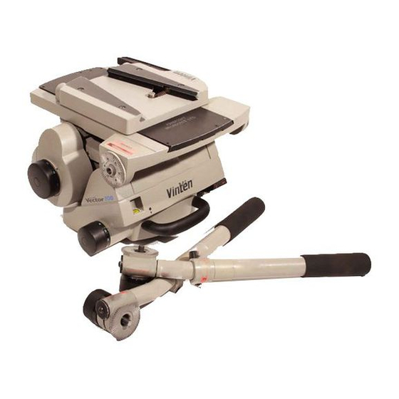
- 1 Fig 6.1 Vector 700/700H (Black) Pan and Tilt Head
- 2 Fig 6.2 Vector 700/700H (Black) Pan and Tilt Head - Main Assembly
- 3 Fig 6.4 Vector 700/700H (Black) Pan and Tilt Head - Pan Drag/Brake Mechanism
- 4 Fig 6.7 Vector 700 (Black) Pan and Tilt Head - Balance Adjuster Assembly
- 5 Fig 6.9 Vector 700/700H (Black) Pan and Tilt Head - Tilt Brake/Balance Knob/Centre Lock
- 6 Fig 6.13Vector 700/700H (Black) Pan and Tilt Head - Composite Spare Parts List
- Download this manual
Advertisement
Table of Contents

Related Manuals for Vinten Vector 700


Summary of Contents for Vinten Vector 700
- Page 1 Contents Next Previous Page View Vector 700/700H (Black) Nafl]f Camera Control Solutions...
- Page 2 Vinten Broadcast Limited. Vinten, Vision and Quickfit are registered trademarks of Vinten Broadcast Limited.
- Page 3 Particular attention must be paid to cleaning, especially after use in adverse conditions. To order spare parts or to obtain further information, application should be made to Vinten Broadcast Limited or to your local distributor.
- Page 4 Page View Notes to readers This is the on-line version of ‘Vector 700/700H (Black) Pan and Tilt Head Maintenance Manual’ (3458-9). Readers should be aware that the pagination differs between on-line and printed versions. Navigation Clicking the mouse on any blue text will move you around the document.
- Page 5 Contents First Previous Next Previous Page Page Page View Safety - Read This First! Warning symbols in this maintenance manual Where there is a risk of personal injury, injury to others, or damage to the pan and tilt head or associated equipment, comments appear, highlighted by the word WARNING! and supported by the warning triangle symbol.
- Page 6 Page Fig 1.1 Vector 700/700H Pan and Tilt Head ..........12 Fig 4.1 Cleaning Balance Mechanism...
- Page 7 Fig 6.5 Vector 700/700H (Black) Pan and Tilt Head - Brake Lever Support Cap Assembly... . 65 Fig 6.6 Vector 700/700H (Black) Pan and Tilt Head - Mechanism Housing Assembly (Sheet 1) ..68 Fig 6.6...
- Page 8 Contents First Previous Next Previous Page Page Page View Abbreviations The following abbreviations are used in this publication: alternating current pound (weight) Amps Lubricated Friction across flats left hand as required MISO metric thread ASME American Society of Mech Engineers metre assy assembly...
- Page 9 Vector 700 ........
- Page 10 Contents First Previous Next Previous Page Page Page View Design Improvements SERIAL No. DETAILS INFORMATION...
- Page 11 The unique counterbalance system enables payloads with centre of gravity (C of G) heights from 80 mm (3 in.) to 200 mm (8 in.) for Vector 700 and 80 mm (3 in.) to 250 mm (10 in.) for Vector 700H to be maintained in perfect balance over the tilt movement range of ±60°...
- Page 12 Contents First Previous Next Previous Page Page Page View (18) (17) (16) V700_LEF (15) (14) (13) (12) (10) (11) V700_RIT Fig 1.1 Vector 700/700H Pan and Tilt Head...
- Page 13 Contents First Previous Next Previous Page Page Page View A level bubble is fitted to the rear of the head and is provided with a time-delay illumination unit operated by a switch (6). Pan bar mounting points ((14) are located at the rear of the head, on either side of the camera mounting platform.
- Page 14 ..............15 Introduction This section includes instructions for mounting the Vector 700 pan and tilt head, fitting and balancing a camera and operating the head. Refer to Fig 1.1...
- Page 15 - up to 70 kg (154 lb) with C of G height from 80 mm (3 in.) to 200mm (8 in.) for Vector 700 or 80 mm (3 in.) to 250 mm (10 in.) for Vector 700H.
- Page 16 Contents First Previous Next Previous Page Page Page View Confirm that the lever is in the locked position. This is indicated by coloured bands above the lever. When the green band only is visible, the lever is locked. If any of the red band can be seen, the lever is not locked.
- Page 17 Contents First Previous Next Previous Page Page Page View When the payload C of G height adjustment is complete, check that the fore and aft balance remains satisfactory. Re-adjust the position of the sliding plate if necessary. After balancing, release the brakes (2)(3) and exercise the head through both axes to confirm that it operates smoothly.
- Page 18 Contents First Previous Next Previous Page Page Page View Section 3 Tools and Materials General The following tools and consumable materials will be required for servicing, disassembly, repair, assembly and adjustment. Tools Item Part No. Extended 3 mm/4 mm AF 3354-931TL Removing tilt drag spherical-ended hex wrench...
- Page 19 Section 5 of this manual, or the unit may be returned to Vinten Broadcasting limited or your local dealer for repair.
- Page 20 Contents First Previous Next Previous Page Page Page View Cleaning balance mechanism track The balance mechanism tracks are automatically cleaned by built-in wipers, but after use in particularly adverse conditions the tracks may require cleaning. Some dismantling of the head is necessary and it is recommended that this be carried out in clean workshop conditions.
- Page 21 Contents First Previous Next Previous Page Page Page View (11) V70VTRAX (10) V70HTRAX Fig 4.1 Cleaning Balance Mechanism Tracks...
- Page 22 Refit the battery cover plate (4), ensuring battery locates in cover plate. Secure with three screws (1). Press the switch and ensure the lamp is lit for approximately 15 seconds. V70_BATT BATTERY TYPE: 9V,6LR61 (PP3, 6AM6, MN1604, E-BLOCK) Vinten Part No. C550-023 Fig 4.2 Level Bubble Illumination Unit Battery Replacement...
- Page 23 Contents First Previous Next Previous Page Page Page View Adjustments After considerable use the platform slide clamp or pan and tilt brakes may require adjustment. Platform slide clamp adjustment The platform slide clamp should be set so that, in the up or clamped position it prevents the platform slide from being moved, while in the down or released position it allows free adjustment of the slide.
- Page 24 Contents First Previous Next Previous Page Page Page View Pan and tilt brake adjustment Following bedding-in, the pan and tilt brakes may require adjustment. The pan and tilt brakes should be set so that the brakes begin to be applied after approximately one-third of the lever travel (Fig 4.4).
- Page 25 Contents First Previous Next Previous Page Page Page View 14.3 On the underside of the head, remove three screws securing cover plate (3). 14.4 Operate the pan brake lever from the OFF to the ON position. 14.5 If brake pressure is not felt after approximately one-third of the lever travel, turn the locating pin clockwise until this is achieved.
- Page 26 Contents First Previous Next Previous Page Page Page View To reposition the wedge adaptor (Fig 4.5): 16.1 Engage the centre lock and remove the load. 16.2 Hold the body of the wedge adaptor and use a 4 mm hexagon wrench to remove four securing screws (1).
- Page 27 ..............13 Balance adjuster assembly (Vector 700) .
- Page 28 ............. . . 37 General This section details procedures for disassembly and assembly of the Vector 700 head. Reference is made in the procedures to figures in Section 6 - Illustrated Parts List.
- Page 29 Contents First Previous Next Previous Page Page Page View To dismantle the platform assembly, proceed as follows (Fig 6.10): Remove two screws (22) securing tilt brake centre (21) and brake disc (tilt) assembly (20) to the platform (28). Pull out two Spirol pins (3). Release the sliding plate clamp (24).
- Page 30 Contents First Previous Next Previous Page Page Page View Tilt brake/balance knob/centre lock Remove the balance knob and associated components as follows (Fig 6.9): Carefully prise out the knob bung (29) Remove screw (28) and washer (27). Pull off the balance knob (26) and remove drag knob boss (25).
- Page 31 WARNING!: The tilt drag assembly is an hermetically sealed unit. Do not attempt to dismantle the assembly beyond the level detailed below. NOTE: An extended 3 mm AF spherical-ended hex wrench (Vinten Part No. 3354-931TL) is required to remove the tilt drag assembly.
- Page 32 13.12 Pull the adjuster assembly (14) and two shims (13) out of the mechanism housing. Recover bevel pinion (39) if not already removed. NOTE: An extended 4 mm AF spherical-ended hex wrench (Vinten Part No. 3354-931TL) is required to remove the support caps 13.13 Referring to...
- Page 33 13.21 In the mechanism housing, remove bearings (12) from central hubs if required. Remove rear tilt buffer (20) if required. Balance adjuster assembly (Vector 700) NOTE: The balance adjuster was improved at Serial No. 785. The earlier balance adjuster (3354-14) should be replaced with the redesigned balance adjuster (3554-54).
- Page 34 Contents First Previous Next Previous Page Page Page View 15.5 Unscrew adjuster shaft (11) from carriage (9). To remove track rollers (1), shims (2), track wiper mouldings (3) and track wiper outers (4) from carriage, undo grub screws (8) and pull out roller axles (5, 10 and 12).
- Page 35 Contents First Previous Next Previous Page Page Page View 17.6 Remove pan bearing nut (47) and pull out two dowels (46). An M3 screw may be installed in the dowels to assist in removal. 17.7 Note orientation and remove four screws (23) and three screws (24) securing brake reaction plate (22) to base (1).
- Page 36 Contents First Previous Next Previous Page Page Page View 17.2 17.1 PAN_TIME Fig 5.1 Pan Drag Timing Mark 19.4 Install the idler gear (10) on the right-hand pillar of the sub-plate (9), ensuring it meshes correctly with the bevel gear. 19.5 Install two gear strap shims (13) and the gear strap (12) and secure with two circlips (3).
- Page 37 Contents First Previous Next Previous Page Page Page View 19.11 Position the base housing (1) upside-down on the bench and install the assembled pan sub- plate, ensuring pan drag cut-out aligns with base knob boss, holes align with holes in base and the ‘O’ ring (4) on brake boss locates correctly in base.
- Page 38 Page Page View Balance adjuster assembly (Vector 700) NOTE: The balance adjuster was improved at Serial No. 785. The earlier balance adjuster (3354-14) should be replaced with the redesigned balance adjuster (3554-54). To assemble the balance adjuster assembly, proceed as follows (Fig 6.7):...
- Page 39 Contents First Previous Next Previous Page Page Page View Balance adjuster assembly (Vector 700H) NOTE: The balance adjuster was improved at Serial No. 785. The earlier balance adjuster (3354-14) should be replaced with the redesigned balance adjuster (3554-54). To assemble the balance adjuster assembly, proceed as follows (Fig 6.8): 21.1 Using Easyrun 50 grease, lubricate track rollers (1), shims (2) thread of adjuster shaft (11) and...
- Page 40 Contents First Previous Next Previous Page Page Page View Balance mechanism and support caps To assemble the balance mechanism, proceed as follows (Fig 6.6): NOTE: Shim (18) is available in two thicknesses - 0.005 in. (3354-206) and 0.003 in. (3354-299). Shim (39) is available in three thicknesses - 0.005 in.
- Page 41 Contents First Previous Next Previous Page Page Page View UPPER DRIVE ARM HORIZONTAL TRACK ARM MECHANISM HOUSING UPPER DRIVE ARM O.OO5 in. SHIM O.OO5 in. HERE SHIM HERE LOWER DRIVE ARM UPPER DRIVE ARM LOWER DRIVE ARM BASE V70SHIMS Fig 5.2 Balance Mechanism Shims...
- Page 42 Contents First Previous Next Previous Page Page Page View 22.7 Referring to 5.2, calculate the shims required between the lower drive arm (21) and the mechanism housing (10) as follows: 22.7.1 Measure the width across the lower bearing faces of the mechanism housing - dimension E.
- Page 43 Contents First Previous Next Previous Page Page Page View 22.19 Install RH actuator shaft in mechanism housing, passing shaft through RH actuator (40), bearings (12) and shim (13), Do not push the shaft fully home. 22.20 Position bevel pinion (39) in adjuster assembly. Push bevel pinion shaft (35) through RH actuator shaft and into bevel pinion.
- Page 44 Contents First Previous Next Previous Page Page Page View 23.2.3 Install washer (12) and washer (11) and secure with nut (10), 23.2.4 Install cap (9). 23.3 Position pan brake lever (16) and tilt brake lever (19) in support cap (1) and install brake lever pivot pin (21).
- Page 45 25.2 Position LH and RH support caps on the balance mechanism, ensuring correct shims are installed on drive arm pins. NOTE: An extended 4 mm AF spherical-ended hex wrench (Vinten Part No. 3354-931TL) is required to install the support caps.
- Page 46 Contents First Previous Next Previous Page Page Page View 26.8 Install shaft support (17) on adjustment shaft assy (6) and secure lightly to platform with two screws (18). Position shaft support to remove end float on adjustment shaft assy and tighten two screws (18).
- Page 47 Contents First Previous Next Previous Page Page Page View Tilt brake To assemble the tilt brake components, proceed as follows (Fig 6.9): 28.1 If the push rod/spring fork assembly was dismantled, assemble as follows: 28.1.1 On the pin (18) arrange 19 disc springs (17) as shown in 6.9.
- Page 48 Contents First Previous Next Previous Page Page Page View 30.4 Centralize pin (24) and install drag knob boss (25). 30.5 Install the balance knob (26) and secure with washer (27) and screw (28). 30.6 Install knob bung (29). Tilt Drag Install the tilt drag mechanism as follows (Fig 6.9):...
- Page 49 Contents First Previous Next Previous Page Page Page View 25.3 25.1 25.2 44.1 TILT_ADJ Fig 5.3 Tilt Drag Knob Adjustment Final adjustment Tilt brake The tilt brake is adjusted by inserting a 2 mm hexagon wrench through the hole in the bottom of the tilt unit cover (33) and turning the pushrod/spring assembly grub screw (19).
- Page 50 33.4 Operate the pan brake lever (16) to the OFF position and ensure that the head is free to rotate. Pan bearing The pan bearing is adjusted by tightening or slackening nut (47), using pan bearing nut key (Vinten Part No. 3448-902TL). Adjust the pan bearing as follows (Fig 6.4):...
- Page 51 Contents First Previous Next Previous Page Page Page View 36.3 Connect the battery and position in forward LH compartment. Install LH cover plate (14) and secure with three screws (6). 36.4 Press bubble illumination switch and ensure LED is lit for approximately 15 seconds. 36.5 Install RH cover plate (7) and secure with three screws (6).
-
Page 52: Table Of Contents
....86 Introduction This parts list is issued for the VECTOR 700/700H (Black) pan and tilt heads manufactured by VINTEN BROADCAST LIMITED, Western Way, Bury St Edmunds, Suffolk, IP33 3TB, England. -
Page 53: Ordering Spare Parts
PART No. Vector 700 (Black) Pan & Tilt Head - with four-hole flat base 3458-3 Vector 700 (Black) Pan & Tilt Head (USA) - with lightweight Mitchell adaptor 3458-5 Vector 700H (Black) Pan & Tilt Head - with four-hole flat base 3458-3H Vector 700H (Black) Pan &... - Page 54 Contents First Previous Next Previous Page Page Page View...
-
Page 55: Fig 6.1 Vector 700/700H (Black) Pan And Tilt Head
Contents First Previous Next Previous Page Page Page View V700IPB1 Fig 6.1 Vector 700/700H (Black) Pan and Tilt Head... - Page 56 Contents First Previous Next Previous Page Page Page View Fig 6.1 Vector 700/700H (Black) Pan and Tilt Head Item Part No Nomenclature 3458-3 Vector 700 Head (black), comprising: 3458-11 Main Assembly Vector 700 Black (Fig 6.2) 3460-3 Wedge adaptor assembly (Fig 6.12)
-
Page 57: Fig 6.2 Vector 700/700H (Black) Pan And Tilt Head - Main Assembly
Contents First Previous Next Previous Page Page Page View V700IP05 Fig 6.2 Vector 700/700H (Black) Pan and Tilt Head - Main Assembly... - Page 58 Contents First Previous Next Previous Page Page Page View Fig 6.2 Vector 700/700H (Black) Pan and Tilt Head - Main Assembly Item Part No Nomenclature 3458-11 Main Assembly Vector 700 (black), comprising: – Tilt brake/balance knob/centre lock (Fig 6.9) 3554-16 Platform assembly (Fig 6.10)
-
Page 59: Fig 6.3 Vector 700/700H (Black) Pan And Tilt Head - Base
Contents First Previous Next Previous Page Page Page View V700IP03 Fig 6.3 Vector 700/700H (Black) Pan and Tilt Head - Base... - Page 60 First Previous Next Previous Page Page Page View Fig 6.3 Vector 700/700H (Black) Pan and Tilt Head - Base Item Part No Nomenclature M006-718 Screw, cap head, socket, M5 x 40 mm long 3458-23 Support Cap Assembly, RH, Black (Fig 6.5)
-
Page 61: Fig 6.4 Vector 700/700H (Black) Pan And Tilt Head - Pan Drag/Brake Mechanism
Contents First Previous Next Previous Page Page Page View 41 42 V700IP02 Fig 6.4 Vector 700/700H (Black) Pan and Tilt Head - Pan Drag/Brake Mechanism... - Page 62 Contents First Previous Next Previous Page Page Page View Fig 6.4 Vector 700/700H (Black) Pan and Tilt Head - Pan Drag/Brake Mechanism Item Part No Nomenclature 3458-24* Base housing (bonding) assembly (Fig 6.3) 3354-312 Rocker arm (Pan brake) (Fig 6.5)
- Page 63 Contents First Previous Next Previous Page Page Page View Fig 6.4 Vector 700/700H (Black) Pan and Tilt Head - Pan Drag/Brake Mechanism (Cont) Item Part No Nomenclature 3448-249 Serrated boss - pan drag knob M600-309 Washer, plain, large, M5 M006-737...
- Page 64 Contents First Previous Next Previous Page Page Page View 24.00 mm ARRANGE TWENTY DISC SPRINGS AS SHOWN V70_ip05...
-
Page 65: Fig 6.5 Vector 700/700H (Black) Pan And Tilt Head - Brake Lever Support Cap Assembly
Next Previous Page Page Page View Fig 6.5 Vector 700/700H (Black) Pan and Tilt Head - Brake Lever Support Cap Assembly Fig 6.5 Vector 700/700H (Black) Pan and Tilt Head - Brake Lever Support Cap Assembly Item Part No Nomenclature 3458-23 Support Cap Assembly, RH.Black (Vector 700), comprising:... - Page 66 Next Previous Page Page Page View Fig 6.5 Vector 700/700H (Black) Pan and Tilt Head - Brake Lever Support Cap Assembly (Cont) Item Part No Nomenclature P001-018* Bearing, plain, du bush, 8 mm ID x 10 mm OD x 12 mm long...
- Page 67 First Previous Next Previous Page Page Page View Fig 6.5 Vector 700/700H (Black) Pan and Tilt Head - Brake Lever Support Cap Assembly (Cont) Item Part No Nomenclature M006-705 Screw, cap head, socket, M5 x 20 mm long M006-704 Screw, cap head, socket, M5 x 16 mm long...
-
Page 68: Fig 6.6 Vector 700/700H (Black) Pan And Tilt Head - Mechanism Housing Assembly (Sheet 1)
Contents First Previous Next Previous Page Page Page View V700IP06 Fig 6.6 Vector 700/700H (Black) Pan and Tilt Head - Mechanism Housing Assembly (Sheet 1) - Page 69 Previous Next Previous Page Page Page View Fig 6.6 Vector 700/700H (Black) Pan and Tilt Head - Mechanism Housing Assembly Item Part No Nomenclature M006-702 Screw, cap head, socket, M5 x 10 mm long 3354-16 Platform assembly (Vector 700), OR...
-
Page 70: Fig 6.6 Vector 700/700H (Black) Pan And Tilt Head - Mechanism Housing Assembly (Sheet 2)
Contents First Previous Next Previous Page Page Page View V700IP07 Fig 6.6 Vector 700/700H (Black) Pan and Tilt Head - Mechanism Housing Assembly (Sheet 2) - Page 71 First Previous Next Previous Page Page Page View Fig 6.6 Vector 700/700H (Black) Pan and Tilt Head - Mechanism Housing Assembly (Cont) Item Part No Nomenclature 3458-19 Tilt drag unit assembly, including P302-017 Bearing, ball, radial, 30 mm ID x 42 mm OD x 7 mm long, two seals P605-003 Snap ring, external, 30 mm shaft dia.
-
Page 72: Fig 6.7 Vector 700 (Black) Pan And Tilt Head - Balance Adjuster Assembly
Contents First Previous Next Previous Page Page Page View 4.5 mm V70_ip08 Fig 6.7 Vector 700 (Black) Pan and Tilt Head - Balance Adjuster Assembly... - Page 73 Previous Next Previous Page Page Page View Fig 6.7 Vector 700 (Black) Pan and Tilt Head - Balance Adjuster Assembly Item Part No Nomenclature 3354-54* Adjustment housing assembly (Vector 700), comprising: P603-003* Bearing, track roller, yoke type, 7 mm bore dia., 16 mm roller dia. x 7.8 mm roller width...
-
Page 74: Fig 6.8 Vector 700H (Black) Pan And Tilt Head - Balance Adjuster Assembly
Contents First Previous Next Previous Page Page Page View 4.5 mm V70_ip09 Fig 6.8 Vector 700H (Black) Pan and Tilt Head - Balance Adjuster Assembly... - Page 75 Contents First Previous Next Previous Page Page Page View Fig 6.8 Vector 700H (Black) Pan and Tilt Head - Balance Adjuster Assembly Item Part No Nomenclature 3354-55 Balance adjuster assembly (Vector 700H), comprising: P603-003* Bearing, track roller, yoke type, 7 mm bore dia., 16 mm roller dia. x 7.8 mm roller width 3354-220 Shim (Roller axle)
-
Page 76: Fig 6.9 Vector 700/700H (Black) Pan And Tilt Head - Tilt Brake/Balance Knob/Centre Lock
Contents First Previous Next Previous Page Page Page View Arrange 19 disc springs 48.5 mm as shown V700ip11 Fig 6.9 Vector 700/700H (Black) Pan and Tilt Head - Tilt Brake/Balance Knob/Centre Lock... - Page 77 Contents First Previous Next Previous Page Page Page View Fig 6.9 Vector 700/700H (Black) Pan and Tilt Head - Tilt Brake/Balance Knob/Centre Lock Item Part No Nomenclature 3458-12 Balance mechanism assembly OR 3458-43 Balance mechanism assembly (Fig 6.8) 3354-279 Flap pin...
- Page 78 Contents First Previous Next Previous Page Page Page View Fig 6.9 Vector 700/700H (Black) Pan and Tilt Head - Tilt Brake/Balance Knob/Centre Lock (Cont) Item Part No Nomenclature 3354-292 Knob sleeve boss 3458-37 Tilt cover centre lock assembly, comprising 3354-258...
-
Page 79: Fig 6.10Vector 700/700H (Black) Pan And Tilt Head - Platform Assembly
Contents First Previous Next Previous Page Page Page View V70_ip12 Fig 6.10 Vector 700/700H (Black) Pan and Tilt Head - Platform Assembly... - Page 80 Contents First Previous Next Previous Page Page Page View Fig 6.10 Vector 700/700H (Black) Pan and Tilt Head - Platform Assembly Item Part No Nomenclature 3354-242 Standard platform slide M006-921* Screw, countersunk head, socket, M5 x 10 mm long M806-004* Pin, coiled-spring, 4 mm dia.
-
Page 81: Fig 6.11Vector 700/700H (Black) Pan And Tilt Head - Pan Bars
Contents First Previous Next Previous Page Page Page View V70_ip13 Fig 6.11 Vector 700/700H (Black) Pan and Tilt Head - Pan Bars... - Page 82 Previous Next Previous Page Page Page View Fig 6.11 Vector 700/700H (Black) Pan and Tilt Head - Pan Bars Item Part No Nomenclature 3219-82 Pan bar and clamp assembly, comprising: M007-506 Screw, button head, socket, M6 x 20 mm long...
- Page 83 Previous Next Previous Page Page Page View Fig 6.11 Vector 700/700H (Black) Pan and Tilt Head - Pan Bars (Cont) Item Part No Nomenclature 3219-94 Short fixed bar & clamp assy, comprising: M007-506 Screw, button head, socket, M6 x 20 mm long...
-
Page 84: Fig 6.12Vector 700/700H (Black) Pan And Tilt Head - Wedge Adaptor Assembly
Contents First Previous Next Previous Page Page Page View V70_ip14 Fig 6.12 Vector 700/700H (Black) Pan and Tilt Head - Wedge Adaptor Assembly... - Page 85 Contents First Previous Next Previous Page Page Page View Fig 6.12 Vector 700/700H (Black) Pan and Tilt Head - Wedge Adaptor Assembly Item Part No. Nomenclature 3460-3 Automatic wedge adaptor (black), comprising: 3460-301 Body (machined) L850-054 Threaded-insert, wire thread insert (helicoil), 3/8 in. BSW x 2...
-
Page 86: Fig 6.13Vector 700/700H (Black) Pan And Tilt Head - Composite Spare Parts List
First Previous Next Previous Page Page Page View Fig 6.13 Vector 700/700H (Black) Pan and Tilt Head - Composite Spare Parts List Part No Nomenclature 3354-900SP Adaptor plate kit (for use on ‘Hawk’ and ‘Teal’ pedestals), comprising: 3384-204 Adaptor ring L054-004 Screw, skt cap hd, 3/8 in. - Page 87 First Previous Next Previous Page Page Page View Fig 6.13 Vector 700/700H (Black) Pan and Tilt Head - Composite Spare Parts List (Cont) Part No Nomenclature 3554-923SP Vertical track member assembly (Vector 700) (Black), comprising: 3554-207 Vertical track member 3354-208...
- Page 88 Contents First Previous Next Previous Page Page Page View Fig 6.13 Vector 700/700H (Black) Pan and Tilt Head - Composite Spare Parts List (Cont) Part No Nomenclature 3458-936SP Drive arm assembly, lower (Black), comprising: 3458-203 Lower drive arm 3354-298 N001-043 Plain bearing, 1/4 in.
- Page 89 First Previous Next Previous Page Page Page View Fig 6.13 Vector 700/700H (Black) Pan and Tilt Head - Composite Spare Parts List (Cont) Part No Nomenclature 3458-904SP Vertical track member / actuator assembly repair kit (V700H) (Black) , comprising: 3458-924SP...
- Page 90 Contents First Previous Previous Page Page View Fig 6.13 Vector 700/700H (Black) Pan and Tilt Head - Composite Spare Parts List (Cont) Part No Nomenclature 3448-248 Pan drsg knob M004-102 Pozidrive countersunk head screw M006-737 Low profile socket cap head screw...
Need help?
Do you have a question about the Vector 700 and is the answer not in the manual?
Questions and answers