Table of Contents
Advertisement
Advertisement
Table of Contents

Related Manuals for Vinten Vector 700H


Summary of Contents for Vinten Vector 700H
- Page 1 Vector 700/700H Vinten Camera Control Solutions...
-
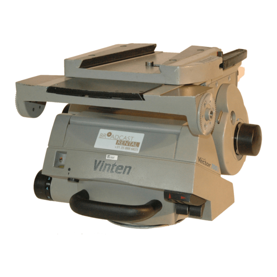
Page 2: Pan And Tilt Head
All rights reserved throughout the world. No part of this document may be stored in a retrieval system, transmitted, copied or reproduced in any way including, but not limited to, photocopy, photograph, magnetic or other record without the prior agreement and permission in writing of Vinten Broadcast Limited. Vinten, Vector and Quickfix are registered trademarks of Vinten Broadcast Limited. -
Page 3: Safety - Read This First
70 kg (154 lb) Payload Centre of Gravity height range Vector 700 80 mm (3 in.) to 200 mm (8 in.) Vector 700H 80 mm (3 in.) to 250 mm (10 in.) Weight (complete with pan bar and wedge adaptor) Vector 700 18.85 kg (41.5 lb) -
Page 4: Further Information
Further information For further information or advice regarding this pan and tilt head, please contact Vinten Broadcast Limited, your local Vinten distributor or visit our website. For details on maintenance and spare parts, please refer to the Vector 700/700H Pan and Tilt Head (Grey) Maintenance Manual and Illustrated Parts List (Publication Part No. -
Page 5: Table Of Contents
Contents Page Safety - Read This First ............3 Technical data . - Page 6 (11) (10) Vector 700/700H Pan and Tilt Head (Left-Hand Side) Wedge adaptor Wedge adaptor operating lever Wedge adaptor screw Pan brake lever Tilt brake lever Carrying handle Level bubble illumination switch Level bubble Pan drag adjustment knob (10) Pan bar clamp (11) Tilt drag adjustment knob...
- Page 7 (18) (17) (12) (16) (13) (15) (14) Vector 700/700H Pan and Tilt Head (Right-Hand Side) (12) Sliding plate (13) Sliding plate adjustment knob (14) Balance adjustment knob (15) Centre lock plunger (16) Centre lock release lever (17) Sliding plate clamp (18) Pan bar mounting...
-
Page 8: Introduction
Introduction The Vector 700/700H pan and tilt head embodies a unique linkage counterbalancing mechanism, thin film (TF) drag assemblies for pan and tilt motions and an adjustable camera mounting plate. The balance system is easily adjusted by a knob (14) on the right-hand side of the head. -
Page 9: Operation
Mounting the head NOTE: When mounted on Vinten ‘Hawk’ or ‘Teal’ pedestals, clearance between the head and the pedestal weight tray prevents the use of 5.5 lb (1.6 kg) and 1.0 lb (0.47 kg) trim weights. Use alternative weights or fit the adaptor plate kit (Part No. -
Page 10: Pan Bars
Vector 700 - up to 70 kg (150 lb) with C of G height from 80 mm (3 in) to 200 mm (8 in). Vector 700H - up to 70 kg (150 lb) with C of G height from 80 mm (3 in) to 250 mm (10 in). -
Page 11: Balancing The Head
Balancing the head NOTE: It is important that the pan bar(s) and all camera accessories (lens, zoom and focus controls, viewfinder, prompter etc.) are fitted in their operational position before balancing the head. Any equipment fitted or adjusted later will unbalance the head. -
Page 12: Locking The Platform
After balancing, release the brakes and exercise the head through both axes to confirm that it op- erates smoothly. Locking the platform The centre lock mechanism is operated by a plunger on the right-hand side of the head. To en- gage the lock, hold the platform in the horizontal position and push the plunger (15) inwards until... -
Page 13: Servicing
Servicing General The Vector 700/700H pan and tilt head is robustly made to high engineering standards and little attention is required to maintain serviceability save regular cleaning. Routine maintenance on the Vector 700/700H pan and tilt head is limited to annual replacement of the level bubble illumination unit battery. - Page 14 Install the platform (20) on the balance mechanism (21) and secure with six screws (19), using Loctite 222E. Using the adjustment knob (13) wind the sliding plate forwards to the central position. Refit the payload (if required) and rebalance the head. (19) (22) (20)
- Page 15 Horizontal tracks No dismantling is necessary to clean the horizontal tracks. Proceed as follow: Remove the payload (if fitted). Set the balance mechanism to its maximum setting by pushing in the knob (14) and turning it clockwise to its stop. Tilt the platform fully backwards and apply the tilt brake (5).
-
Page 16: Routine Maintenance
Routine maintenance Level bubble illumination unit battery replacement The level bubble on the Vector 700/700H pan and tilt head is illuminated by a battery-powered light-emitting diode (LED). A time-delay circuit initiated by a switch controls the LED. The battery should be replaced at yearly intervals or whenever the illumination is considered inadequate. NOTE: Dependent on the type of mounting, it may be necessary to remove the head from the mounting for access to the battery compartment. -
Page 17: Adjustments
Adjustments After considerable use the platform slide clamp may require adjustment. To enable the payload to be correctly balanced, the wedge adaptor may require repositioning. The pan and tilt brakes may require adjustment after considerable use. Platform slide clamp adjustment The platform slide clamp should be set so that, in the up or clamped position it prevents the plat- form slide from being moved, while in the down or released position it allows free adjustment of the slide. -
Page 18: Repositioning The Wedge Adaptor
Repositioning the wedge adaptor The wedge adaptor is secured by four cap head screws which pass through the wedge adaptor into the sliding plate (12). WARNING! Overlong screws will prevent the sliding plate from operating. Always use the screws provided (M6 x 30 mm). To reposition the wedge adaptor: Engage the centre lock (See Locking the platform) -
Page 19: Pan And Tilt Brake Adjustment
Pan and tilt brake adjustment The pan and tilt brakes should be set so that the brakes begin to be applied after approximately one-third of the lever travel. The tilt brake is adjusted by inserting a 2 mm hexagon wrench through the hole (5.2) in the bottom of the tilt unit cover and turning the grub screw (5.1). - Page 20 The pan brake is adjusted by turning the pin (4.1). To gain access to the pin it is necessary to re- move the payload from the head, remove the head from its mounting and remove a cover plate (29) from the underside of the head. To adjust the pan brake, proceed as follows: WARNING! Remove the payload before adjusting the pan brake.
-
Page 21: Parts List
Parts List The following list includes the main assemblies, user-replaceable spare parts and optional acces- sories. For further information regarding repair or spare parts, please contact Vinten Broadcast Limited or your local distributor. For information on-line, visit our website at www.vinten.com... -
Page 22: Optional Accessories
Optional accessories Lightweight Mitchell adaptor 3103-3 Heavy-duty Mitchell adaptor - for Vinten pedestal mounting in conjunction with Hi-hat adaptor Part No. 3055-3 3724-3 Adaptor plate kit - for use on Hawk and Teal pedestals 3354-900SP...
Need help?
Do you have a question about the Vector 700H and is the answer not in the manual?
Questions and answers