Table of Contents
Advertisement
Advertisement
Table of Contents

Related Manuals for Vinten Pro-Ped


Summary of Contents for Vinten Pro-Ped
- Page 1 Pro-Ped Vinten Camera Control Solutions...
- Page 2 All rights reserved throughout the world. No part of this document may be stored in a retrieval system, transmitted, copied or reproduced in any way including, but not limited to, photocopy, photograph, magnetic or other record without the prior agreement and permission in writing of Vinten Broadcast Limited. Vinten is a registered trademarks of Vinten Broadcast Limited.
-
Page 3: Safety - Read This First
Safety - read this first Warning Symbols in this Operators Guide Where there is a risk of personal injury, injury to others, or damage to the ped- estal or associated equipment, comments appear, highlighted by the word WARNING! and supported by the warning triangle symbol. Warning symbols on the pedestal On encountering the warning triangle and open book symbols it is imperative that you consult this operators guide before using this pedestal or attempting... -
Page 4: Technical Data
11.38 bar (165 psi) Usage The Pro-Ped Pedestal is designed for use in television studios and on location to support and bal- ance a pan and tilt head, camera and ancillary equipment weighing up to 55 kg (120 lb). Pedestal is intended for use by television camera operators. -
Page 5: Table Of Contents
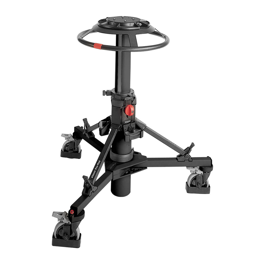
.Fitting and balancing the load..........12 Using the Pro-Ped pedestal Height adjustment. - Page 6 (23) (22) (21) (20) (19) (18) (17) (13) (16) (10) (15) (14) (13) (12) (11) Pro-Ped Pedestal (Studio Version)
- Page 7 Pro-Ped Pedestal (Studio Version) Four-bolt mounting plate Control valve Pressure gauge Top stage Drag control Bottom stage Safety catch Trim weight Long strut (10) Velcro strap (11) Cable guard (12) Track lock pin (13) Short strut (14) Skid clamp (15)
-
Page 8: Introduction
Introduction The Pro-Ped pedestal comprises a central two-stage telescopic column and a skid assembly with castoring wheels. For transport and storage, the column and skid may be separated and the skid folded. The top stage may be pressurized manually, using the self-contained pump, or from an exter- nal pressure source. -
Page 9: Operation
Operation Assembling the pedestal Turn the skid upside-down, depress the leg locking plungers and swing each folding leg out until the plungers lock the legs in the open position. Set the skid on the ground on its wheels and apply the brakes (15). Install the column on the skid as follows: Ensure that the rubber straps on each foot support (16) -
Page 10: Pressurizing The Pedestal
Do not attempt to adjust the pressure relief valve The Pro-Ped may be pressurized manually, by using the self-contained pump, or from an external source. A correctly pressurized pedestal will balance its payload such that it can be moved to any position over the full on-shot stroke of the top stage, with minimum effort, and it will maintain its position when the steering ring is released. - Page 11 Pressurizing manually To pressurize the pedestal manually, proceed as follows: Set the control valve to the PUMP position. WARNING! Bottom stage elevation is assisted by a gas strut. The bottom stage will rise rapidly if released with no payload fitted. Do not lean over the pedestal when releasing the safety catch and/or the bottom clamp Ensure that the bottom stage...
-
Page 12: Fitting And Balancing The Load
When the camera mount has been fitted, the bolts should be tightened se- curely using a spanner of the correct size. A Vinten spanner, Part No. J551-001, is available for this purpose. -
Page 13: Using The Pro-Ped Pedestal
Using the Pro-Ped pedestal Height adjustment Lower stage NOTE: Lower stage pressure-assistance is provided by a gas strut located within the column. The strut is available in four pressure settings and the correct one should be installed according to the pedestal load. - Page 14 pin will only engage with the wheel when the wheel is properly aligned. This arrangement provides castor, track and steer motion. WARNING! To ensure maximum stability, particularly when moving over uneven ground, reduce pedestal height to a minimum. Castor motion For castor motion, disengage all three track locks (12).
-
Page 15: Transportation And Storage
Transportation and storage WARNING! Local, national or international regulations may apply to the transport and storage of pressurized pedestals. NOTE: It is not necessary to reduce the pedestal pressure prior to transportation or storage and the pan and tilt head may be removed with the pedestal in the fully depressed and locked position. -
Page 16: Servicing
Servicing General The Pro-Ped pedestal is robustly made to high engineering standards and little attention is re- quired to maintain serviceability save regular cleaning. Attention to the following points will ensure a long and useful service life with minimum need for repair. - Page 17 Bottom clamp adjustment When applied finger-tight, the ‘V’ notch on the bottom clamp knob should be within the limits shown. To adjust the bottom clamp (19): Tighten the clamp finger-tight. Remove the hole plug (19.1). Remove the screw (19.2) and washer (19.3) securing knob (19)
-
Page 18: Skid Clamp Adjustment
Skid clamp adjustment To adjust the skid clamp: The skid clamp (14) is applied or released by turning the handle clockwise or counter-clock- wise. The handle has a pull-off/push-on ratchet adjustment. To take up wear, pull the han- dle away from the spindle, rotate counter-clockwise and release. Repeat the above procedure, as necessary, until the clamp locks when applied but allows free movement when released. - Page 19 Replacing gas struts Bottom stage elevation assistance is provided by a gas strut located in the telescopic column. To allow for various column loads, four versions of the strut are available, each designed to operate over a particular load range. To replace the bottom stage gas strut: Apply the wheel brakes (15), set the top stage to its maximum height and engage the...
-
Page 20: Elimination Of Radial And Side Play On The Top Stage
Unscrew and remove the centre end plug (24.1) from the base of the telescopic column. Withdraw the gas strut (24.2) from the column. Fit the new gas strut, cylinder end first, carefully guiding it up through the column until it is fully engaged. -
Page 21: Parts List
Parts list The following lists include main assemblies, user-replaceable spare parts and optional accesso- ries. For further information regarding repair or spare parts, please contact Vinten Broadcast Ltd or your local distributor. For information on-line, visit our website at www.vinten.com.
Need help?
Do you have a question about the Pro-Ped and is the answer not in the manual?
Questions and answers