Sign In
Upload
Download
Table of Contents
Contents
Add to my manuals
Delete from my manuals
Share
URL of this page:
HTML Link:
Bookmark this page
Add
Manual will be automatically added to "My Manuals"
Print this page
×
Bookmark added
×
Added to my manuals
Manuals
Brands
Vinten Manuals
Camera Accessories
Fulmar Pedestal
Maintenance manual
Vinten Fulmar Pedestal Maintenance Manual
Hide thumbs
1
2
3
4
5
6
7
8
9
10
11
12
13
14
15
16
17
18
19
20
21
22
23
24
25
26
27
28
29
30
31
32
33
34
35
36
37
38
39
40
41
42
43
44
45
46
47
48
49
50
51
52
53
54
55
56
57
58
59
60
61
62
63
64
65
66
67
68
69
70
71
72
73
74
75
76
77
78
79
80
81
82
83
84
Table Of Contents
85
page
of
85
Go
/
85
Contents
Table of Contents
Bookmarks
Table of Contents
Safety Information
Critical Data
Contents
Technical Specification
Pressure Tank Assembly Diagram
Safety Valve Assembly Diagram
Pressure Gauge Assembly
Introduction and Description
Product View and Parts Identification
Base
Column
Head Mounting Platform
Pneumatic System
Operation
Putting into Service
Unpacking
Steering Mechanism Checks
Attachment of Pan and Tilt Heads
Nitrogen Charging Procedure
Pressurization Graph
Column Locking
Balancing
Manoeuvring the Pedestal
Column Brake
Cable Guard
Tools and Materials
Servicing
Cleaning
Nitrogen Charging
Leak Check
Safety Valve Check
Chain Tension
Lubrication
Wheel Tracking
Steering Chains and Bearings Lubrication
Change-Over Gear Lubrication
Adjustments
Chain Tensioning
Wheel Alignment
Column Guide Roller Adjustment
Steering Ring Adjustment
Repair
Disassembly
Column Bearings
Steering Assembly
Column and Ram
Ram
Safety Valve, Charging Valve and Pressure Gauge
Assembly
Arrangement of Cords and Chains in the Column
To Assemble the Ram
To Install the Ram
To Install the Steering Assembly
To Install Column Bearings
Other Replacements
Illustrated Parts List
Main Assembly Part Numbers
Top Tube View
Centre Tube View
Bottom Tube View
Fixed Tube View
Tank View
Ram Assembly and Ram Plates View
Weight Tray Assembly View
Steering Assembly View
Wheel Housing Assembly (Steering) View
Wheel Housing Assembly (Adjustable Sprocket) View
Wheel Housing Assembly (Fixed) View
Wheel Assembly View
Covers and Cable Guards View
Advertisement
Quick Links
1
Critical Data
2
Technical Specification
3
Pressure Tank Assembly Diagram
4
Pneumatic System
5
Nitrogen Charging Procedure
Download this manual
Contents
Next
Previous
Page
View
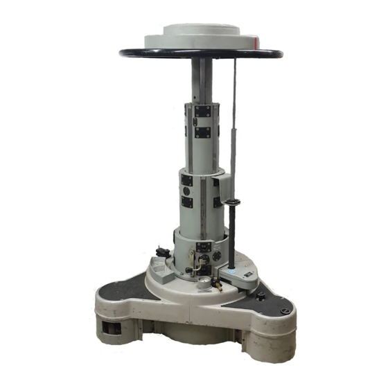
Fulmar
Vinten
Camera Control Solutions
Table of
Contents
Previous
Page
Next
Page
1
2
3
4
5
Advertisement
Table of Contents
Need help?
Do you have a question about the Fulmar Pedestal and is the answer not in the manual?
Ask a question
Questions and answers
Related Manuals for Vinten Fulmar Pedestal
Camera Accessories Vinten FH-145 User Manual
Pan and tilt head (28 pages)
Camera Accessories Vinten FHR-145 User Manual
Pan and tilt head (28 pages)
Camera Accessories Vinten flowtech 75 User Manual
(20 pages)
Camera Accessories Vinten V4160-0001 User Manual
(28 pages)
Camera Accessories Vinten V4150-0004 User Manual
(28 pages)
Camera Accessories Vinten FH155 Manual User Manual
Robotic and manual pan and tilt heads (28 pages)
Camera Accessories Vinten RADAMEC Fusion FH-100 Operator's Manual
Robotic and manual pan & tilt head (38 pages)
Camera Accessories Vinten FHR-35 User Manual
Robotic pan and tilt head (32 pages)
Camera Accessories Vinten FE-55 User Manual
Robotic elevation unit (40 pages)
Camera Accessories Vinten FE-165 Light User Manual
Robotic elevation unit (40 pages)
Camera Accessories Vinten Osprey Light Operator's Manual
Pedestal (31 pages)
Camera Accessories Vinten Osprey Plus Operator's Manual
Single-stage pedestal (19 pages)
Camera Accessories Vinten 3320 Maintenance Manual
Vision pedestal (53 pages)
Camera Accessories Vinten OSPREY plus User Manual
Pedestal (36 pages)
Camera Accessories Vinten V4045-4980 Operator's Manual
Vision as range pan and tilt heads (32 pages)
Camera Accessories Vinten Vision 250 Service Manual
Pan and tilt head (60 pages)
This manual is also suitable for:
3702
Table of Contents
Print
Rename the bookmark
Delete bookmark?
Delete from my manuals?
Login
Sign In
OR
Sign in with Facebook
Sign in with Google
Upload manual
Upload from disk
Upload from URL


Need help?
Do you have a question about the Fulmar Pedestal and is the answer not in the manual?
Questions and answers