Table of Contents
Advertisement
Advertisement
Table of Contents

Related Manuals for Vinten Osprey Light


Summary of Contents for Vinten Osprey Light
- Page 1 Osprey Light Vinten Camera Control Solutions...
- Page 2 Vitec Group plc. Vinten® and Quickfix® are registered trademarks of Vitec Group plc. Printed in Great Britain by DPS, Newmarket, Suffolk...
- Page 3 De originale instruktioner, der præsenteres i denne betjeningsvejledning, er skrevet på engelsk og derefter oversat til andre sprog. Hvis du ikke forstår disse instruktioner bedes du kontakte Vinten eller vor forhandler for at få en oversættelse af de originale instruktioner (EU-lande).
- Page 4 Scríobhadh na treoracha bunaidh don treoirleabhar oibritheora seo as Béarla, agus aistríodh iad go teangacha eile ina dhiaidh sin. Mura bhfuil tú in ann na treoracha seo a thuiscint, téigh i dteagmháil le Vinten nó le do dháileoir, chun aistriúchán de na treoracha bunaidh a fháil (Tíortha an AE).
- Page 5 Instrucţiunile originale prezentate în acest ghid pentru operatori au fost scrise în limba engleză, şi traduse ulterior în alte limbi. În cazul în care nu înţelegeţi aceste instrucţiuni, contactaţi Vinten sau distribuitorul dumneavoastră pentru a obţine o traducere a instrucţiunilor originale (Ţările UE).
-
Page 6: Preface
Features and benefits of your new Osprey Light pedestal The Osprey Light pedestal has been specifically designed to meet the exacting demands of cam- era operators working with lightweight studio cameras. The Osprey Light pedestal offers a high level of control with many unique features. -
Page 7: Safety - Read This First
The original instructions presented in this operators guide were written in English, and subse- quently translated into other languages. If you are unable to understand any of the translated lan- guages, contact Vinten or your distributor to obtain a translation of the original instructions (EU Countries). -
Page 8: Regulatory Information
Back Regulatory information This product conforms to the following European Directives: 2006/42/EC (CE Marking Directive) 98/37/EC (Machinery Directive) (89/392/EC) 97/23/EC (Pressure Equipment Directive - SEP) 2001/95/EC (General Product Safety) This product has been manufactured in accordance with BS EN ISO 9001/2000 Harmonised standards applied: BS EN ISO 12100-2:2003 (Safety of machinery—Basic Concepts, general principles for de- sign, Part 2: Technical principles. -
Page 9: Table Of Contents
Parts List ..............31 Associated Publication Osprey Light Pedestal Maintenance Manual and illustrated Parts List... -
Page 10: Technical Data
-20°C / +60°C (-4°F / +140°F) Usage The Osprey Light pedestal is designed for use in television studios and on location to support and balance a pan and tilt head, camera and ancillary equipment weighing up to 40 kg (88 lb). -
Page 11: Further Information
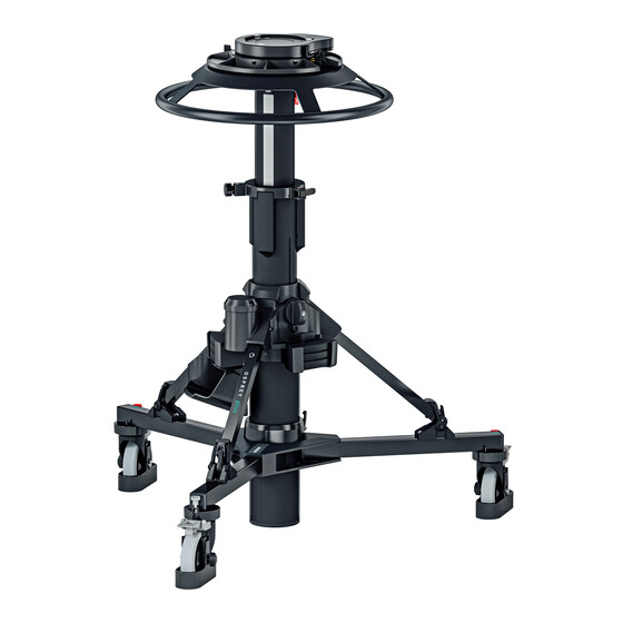
Vinten distributor (see back cover) or visit our website. For details on maintenance and spare parts, please refer to the Osprey Light Pedestal Mainte- nance Manual and Illustrated Parts List (Publication Part No. V3950-4990) This is obtainable from Vinten Broadcast Limited or your local Vinten distributor. - Page 12 Back (28) (27) (26) (25) (24) (23) (22) (21) (20) (19) (18) (17) (16) (10) (11) (11) (15) (14) (13) (12) Fig 1 Osprey Light Pedestal (Studio Version)
- Page 13 Back Osprey Light Pedestal (Studio Version) Schrader valve and cap Pressure gauge viewing window Steering ring Steering indicator Moving column Drag control knob/on-shot clamp Strut Foot support and strap Cable guard adjustment knob (10) Cable guard (11) Folding leg (12)
-
Page 14: Introduction
Back Introduction The Osprey Light pedestal is a fully-portable pneumatic camera mount, designed to support a payload of up to 40 kg (88 lb). It is available in OB and Studio versions. The pedestal has a central single-stage telescopic column, supported on a skid assembly with crabbing wheel steering. -
Page 15: Operation
Back Operation Assembling the pedestal Skid Turn the skid upside-down, depress the leg locking plungers (11.1) and swing each folding leg (11) out until the plungers lock the legs in the fully open position. NOTE: The kick ring can be fitted in only one position, with the shorter strut on the fixed leg. -
Page 16: Setting The Control Valve
Back Column Install the column on the skid as follows: Fully slacken the skid clamp (16) and ensure that the rubber straps on each foot support are to the outside of the ball joint. Ensure the control valve (26) is set to the WORK position. Release the Velcro retaining strap (19). -
Page 17: Pressurizing The Pedestal
WORK. Pressurizing the pedestal The Osprey Light pedestal may be pressurized manually using the self-contained pump, Vinten portable pump (Part No. 3357-3) or an external pressure source. A correctly pressurized pedestal will balance its payload, allowing movement over the full on-shot stroke of the moving column with minimum effort, and will maintain its position when the steering ring is released. - Page 18 Back WARNING! 1. Do NOT pressurize the pedestal beyond the maximum safe working pressure indicated by the leading edge of the red sec- tor on the gauge. 2. Do NOT adjust the pressure relief valve. Personal injury and pedestal damage may occur. ≤...
- Page 19 Back To determine the pedestal pressure, proceed as follows: Ensure that the control valve (26) is set to the WORK position (refer to Setting the control valve on page 16). Rotate the steering ring so that the pressure gauge is visible through the viewing window (2).
- Page 20 (26) to extend under the spring force. The control valve (26) will remain in an extended position. Pressurizing the pedestal using the Vinten portable pump (P.1) (P.5) (P.4) (P.2) (P.3) Fig 4 The Vinten Portable Pump...
- Page 21 Back To pressurize the pedestal using the Vinten portable pump, proceed as follows: Fully collapse the moving column and apply the safety catch (24). Set the control valve (26) to the WORK position (refer to Setting the control valve on page 16 for more detail).
-
Page 22: Fitting And Balancing The Load
The Osprey Light pedestal has the standard four-bolt mounting plate (27) which permits the use of various Vinten camera mounts including pan and tilt heads, Quickfix and Mitchell adapters. Fitting the camera mount To fit the camera mount, proceed as follows:... - Page 23 Attaching these items at a later stage may upset the pedestal balance. Pressurize the pedestal to balance the full payload (refer to either Pressurizing the pedestal using the Vinten portable pump on page 20, or Pressurizing from an external pressure source on page 21).
-
Page 24: Using The Pedestal
Back Place a trim weight (28) onto the weight tray (25). NOTE: To remove a trim weight (28) from the trim weight stowage (22), first rotate the trim weight catch (23) through half a turn anti-clockwise. Replace the trim weight catch (23) afterwards to retain remaining stowed trim weights (22). - Page 25 Back Cable guards The cable guards (10) fitted to the studio version are height-adjustable and should be set as re- quired. Adjustment is carried out by slackening the knobs (9), setting the cable guards at the re- quired height and re-tightening the knobs. Cable clamp A cable clamp (18)
-
Page 26: Transportation And Storage
Back Transportation and storage WARNING! 1. Local, national or international regulations may apply to the transport and storage of pressurized pedestals. 2. The control valve (26) MUST be set to the WORK position when degassing the pedestal, or only the pump volume will be vented and the tank volume will remain. - Page 27 Back WARNING! ALWAYS collapse the moving column and engage the safety catch (24) if wheeling the pedestal across uneven/inclined sur- faces between shots with the full payload fitted, to prevent loss of stability. The pedestal may be dismantled for transportation and storage. Proceed as follows: Apply the brakes (15).
-
Page 28: Servicing
Servicing General The Osprey Light pedestal is robustly made to high engineering standards and little attention is required to maintain serviceability save regular cleaning. Attention to the following points will en- sure a long and useful service life with minimum need for repair. - Page 29 Back Drag control knob adjustment When turned fully clockwise, the ‘V’ notch on the drag control knob should be within the limits shown. To adjust the drag control knob: Turn the drag control knob fully clockwise. Remove the hole plug (6.1). Remove the screw (6.2) and washer (6.3)
- Page 30 Back Elimination of radial and side play in the moving column If excessive radial or side play is apparent in the moving column, refer to the appropriate section in the Maintenance Manual. This adjustment should be carried out by a competent person. Steering adjustments Inaccuracies in steering may be due to slackness in the steering belt or steering chains, or inac- curate tracking.
-
Page 31: Parts List
Back Parts List The following list includes the main assemblies, user replaceable spare parts and optional acces- sories. For further information regarding repair or spare parts, please contact Vinten Broadcast Limited or your local distributor. Main assemblies Osprey Light studio version (10 cm wheels and cable guards) V3950-0001 Osprey Light OB version (12.5 cm wheels)
Need help?
Do you have a question about the Osprey Light and is the answer not in the manual?
Questions and answers