Sign In
Upload
Download
Table of Contents
Contents
Add to my manuals
Delete from my manuals
Share
URL of this page:
HTML Link:
Bookmark this page
Add
Manual will be automatically added to "My Manuals"
Print this page
×
Bookmark added
×
Added to my manuals
Manuals
Brands
Vinten Manuals
Camera Accessories
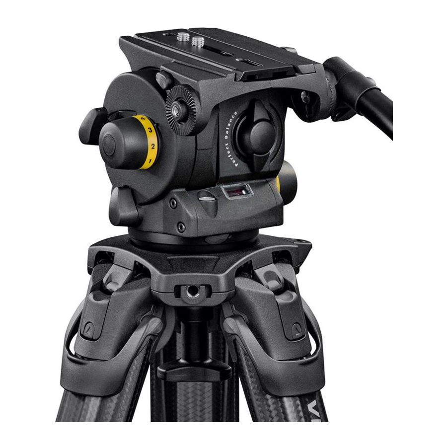
Vision 100
Maintenance manual
Vinten Vision 100 Maintenance Manual
Pan and tilt head
Hide thumbs
Also See for Vision 100
:
Operator's manual
(19 pages)
1
2
3
4
5
6
7
8
9
10
11
12
13
14
15
16
17
18
19
20
21
22
23
24
25
26
27
28
29
30
31
32
33
34
35
36
37
38
39
40
41
42
43
44
45
46
47
48
49
50
51
52
53
54
55
56
57
58
59
60
page
of
60
Go
/
60
Contents
Table of Contents
Bookmarks
Table of Contents
Section 5 Repair
General
Table of Contents
Disassembly
RH Side Plate
Balance Mechanism
Pan Drag Mechanism
Tilt Drag Mechanism
Outrigger
Electrical Installation
Assembly
Electrical Installation
Outrigger and Tilt Drag
Pan Drag Mechanism
Balance Mechanism
RH Side Plate
Final Assembly
Section 6 Illustrated Parts List
Ordering Spare Parts
Introduction
Main Assembly Part Numbers
Fig 6.1 Vision 100 Pan and Tilt Head
Fig 6.2 Vision 100 Pan and Tilt Head - Mechanism Assembly
Fig 6.3 Vision 100 Pan and Tilt Head - Pan Brake and Pan Drag
Fig 6.4 Vision 100 Pan and Tilt Head - Tilt Brake and Tilt Drag
Fig 6.5 Vision 100 Pan and Tilt Head - Balance Mechanism
Fig 6.6 Vision 100 Pan and Tilt Head - Electrical Installation
Fig 6.7 Vision 100 Pan and Tilt Head - Pan Bar
Fig 6.8 Vision 100 Pan and Tilt Head - Composite Spare Parts
Advertisement
Quick Links
1
Table of Contents
2
Rh Side Plate
3
Disassembly
4
Balance Mechanism
5
Tilt Drag Mechanism
6
Fig 6.1 Vision 100 Pan and Tilt Head
7
Fig 6.2 Vision 100 Pan and Tilt Head - Mechanism Assembly
8
Fig 6.3 Vision 100 Pan and Tilt Head - Pan Brake and Pan Drag
Download this manual
Contents
Next
Previous
Page
View
Vision 100
(Black)
Vinten
Camera Control Solutions
Table of
Contents
Previous
Page
Next
Page
1
2
3
4
5
Advertisement
Chapters
Section 5 Repair
29
Section 6 Illustrated Parts List
40
Table of Contents
Need help?
Do you have a question about the Vision 100 and is the answer not in the manual?
Ask a question
Questions and answers
Related Manuals for Vinten Vision 100
Camera Accessories Vinten Vision 100 Operator's Manual
Pan and tilt head (19 pages)
Camera Accessories Vinten Vision 10LF Maintenance Manual
Pan and tilt head (53 pages)
Camera Accessories Vinten V4043-0001 Operating Instructions Manual
Pan & tilt heads (54 pages)
Camera Accessories Vinten Vision 10AS Operator's Manual
Vision as series pan and tilt heads (36 pages)
Camera Accessories Vinten Vision Pozi-Loc 3880-3 Operator's Manual
(19 pages)
Camera Accessories Vinten vector 430 Operator's Manual
Pan and tilt head (26 pages)
Camera Accessories Vinten Vision 8 Maintenance Manual
Pan and tilt head (52 pages)
Camera Accessories Vinten Pro-Ped Operator's Manual
Pedestal (21 pages)
Camera Accessories Vinten V4109-0001 User Manual
Aps scanner (28 pages)
Camera Accessories Vinten Fulmar Pedestal Maintenance Manual
(85 pages)
Camera Accessories Vinten Vision 30 Maintenance Manual
Pan and tilt head (84 pages)
Camera Accessories Vinten Vector 70 Maintenance Manual
Pan and tilt head (94 pages)
Camera Accessories Vinten FH155 Manual User Manual
Robotic and manual pan and tilt heads (28 pages)
Camera Accessories Vinten Vision Pozi-Loc Maintenance Manual
(111 pages)
Camera Accessories Vinten pro-touch Pro-10 System Maintenance Manual
(54 pages)
Camera Accessories Vinten FH-145 User Manual
Pan and tilt head (28 pages)
This manual is also suitable for:
3466
Table of Contents
Save PDF
Print
Rename the bookmark
Delete bookmark?
Delete from my manuals?
Login
Sign In
OR
Sign in with Facebook
Sign in with Google
Upload manual
Upload from disk
Upload from URL


Need help?
Do you have a question about the Vision 100 and is the answer not in the manual?
Questions and answers