Table of Contents
Advertisement
Quick Links
Advertisement
Table of Contents

Related Manuals for Alpha Data ADM-XRC-7Z2


Summary of Contents for Alpha Data ADM-XRC-7Z2
- Page 1 ADM-XRC-7Z2 User Manual Document Revision: 1.2 24th Feb 2020...
- Page 2 ADM-XRC-7Z2 User Manual V1.2 - 24th Feb 2020 © 2020 Copyright Alpha Data Parallel Systems Ltd. All rights reserved. This publication is protected by Copyright Law, with all rights reserved. No part of this publication may be reproduced, in any shape or form, without prior written consent from Alpha Data Parallel Systems Ltd.
-
Page 3: Table Of Contents
ADM-XRC-7Z2 User Manual V1.2 - 24th Feb 2020 Table Of Contents Overview ............................1 Introduction ............................ 1 Key Features ..........................1 Order Code ............................ 1 References & Specifications ......................2 PCB Information ..........................3 Physical Specifications ........................3 Motherboard / Carrier Requirements ..................... 3 Power Requirements ........................ - Page 4 Table 20 XMC Connector P5 .......................... 19 Table 21 XMC Connector P6 .......................... 20 List of Figures Figure 1 ADM-XRC-7Z2 Block Diagram ......................5 Figure 2 DIP Switch Locations ......................... 5 Figure 3 LED Locations ........................... 7 Figure 4 Ethernet Interfaces .......................... 13 Figure 5 Serial COM Ports ..........................
-
Page 5: Overview
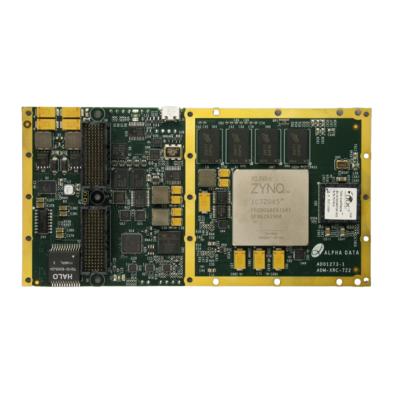
ADM-XRC-7Z2 User Manual V1.2 - 24th Feb 2020 1 Overview 1.1 Introduction The ADM-XRC-7Z2 ("7Z2") is a high-performance Processor XMC for applications using Zynq-7000 SoCs from Xilinx. 1.2 Key Features Key Features • Single-width XMC, compliant to VITA Standard 42.0 and 42.3 •... -
Page 6: References & Specifications
ADM-XRC-7Z2 User Manual V1.2 - 24th Feb 2020 Name Symbol Configurations Kintex-7 Device Z045 , Z100 Kintex-7 Speed 1 , 2 , 3 blank = no 1553 interface MIL-STD-1553 /B = 1553 Bus Interface Fitted blank = air cooled commercial... -
Page 7: Pcb Information
The Secondary XMC connector, P6 has +5V (power) -/+6V (serial port) levels. It is not compatible with XMC.3 or XMC.10 (GPIO). It must not be connected to the Alpha Data ADM-EMC-II or ADM-XMC-II carrier cards. Please contact Alpha Data for carrier card compatibility. -
Page 8: Installation
ADM-XRC-7Z2 User Manual V1.2 - 24th Feb 2020 3 Installation 3.1 Software Installation Please refer to the Software Development Kit (SDK) installation CD. The SDK contains drivers, examples for host control and FPGA design and comprehensive help on application interfacing. -
Page 9: Functional Description
(BU-67301) GPIO (x48) TX-INH MVMRO 1553 A & B Figure 1 : ADM-XRC-7Z2 Block Diagram 4.1.1 Switch Definitions There are two sets of 8-way DIP switches for configuring the board. Their locations are shown in Figure 2 Figure 2 : DIP Switch Locations... - Page 10 ADM-XRC-7Z2 User Manual V1.2 - 24th Feb 2020 Switch 1 Ref. Function OFF State ON State SW1-1 Reserved Flash Boot SW1-2 Allow PS to boot PL from flash Prohibit PS booting PL from flash Inhibit Systom Monitor SW1-3 Normal Operation...
-
Page 11: Led Definitions
ADM-XRC-7Z2 User Manual V1.2 - 24th Feb 2020 4.1.2 LED Definitions There are seven LEDs to provide a visual indication of the board status. Their locations are shown in Figure 3 Figure 3 : LED Locations Comp. Ref. Function ON State... -
Page 12: Primary Xmc Connector P5
ADM-XRC-7Z2 User Manual V1.2 - 24th Feb 2020 A further two sets of three LEDs provide an indication of the status of the two Ethernet interfaces Comp. Ref. Function ON State Off State Ethernet 0 D23 (Green) Table 16 LED0... -
Page 13: Mpresent
The Transmit (Tx) side of all eight lanes are AC coupled by 100nF capacitors, placed at the output from the PL. The Receive (Rx) side of all eight lanes are directly connected from the connector to the PL. Alternative coupling options are available as a special ordering option. Please contact Alpha Data for details. 4.3 Secondary XMC Connector P6... -
Page 14: Pcie Reference Clock (Pcierefclk)
ADM-XRC-7Z2 User Manual V1.2 - 24th Feb 2020 Note: Clock Termination The LVDS clocks do not have termination resistors on the circuit board. On-die terminations in the FPGA must be enabled by setting the attribute "DIFF_TERM = TRUE". This can either be set in the source code when instantiating the buffer, or in the User Constraints File (UCF). -
Page 15: Refclk200M
ADM-XRC-7Z2 User Manual V1.2 - 24th Feb 2020 4.5.4 REFCLK200M The fixed 200MHz reference clock, REFCLK200M, is a differential clock signal using LVDS. Three phase-matched copies are distributed to Global Clock inputs on the Zynq PL. This clock can be used to generate application-specific clock frequencies using the PLLs within the Virtex-6 FPGA. -
Page 16: Bu_Host_Clk
ADM-XRC-7Z2 User Manual V1.2 - 24th Feb 2020 Signal Target FPGA Input IO Standard "P" pin "N" pin BU_REFCLK40M IO_L13_MRCC_12 LVCMOS33 AE28 Table 14 : BU_REFCLK40M Connections 4.5.10 BU_HOST_CLK In addition to the reference clocks, there is an additional clock, BU_HOST_CLK, used for the local bus interface between the Zynq PL and the BU-67301. -
Page 17: Zynq Ps Block
ADM-XRC-7Z2 User Manual V1.2 - 24th Feb 2020 4.7 Zynq PS Block 4.7.1 Boot Modes BootSel1 BootSel0 Boot Mode (SW2-2) (SW2-1) JTAG Quad SPI SD Flash Reserved Table 15 : Boot Mode Selection 4.7.2 PS Memory Interfaces 4.7.2.1 Quad SPI Flash Memory 512Mb of QSPI flash memory (Micron N25Q256A11E1240E/MT41K128M16JT) is attached to the PS, and is used to store Zynq boot images, FPGA bitstreams and data. -
Page 18: Table 16 Ethernet Status Leds
ADM-XRC-7Z2 User Manual V1.2 - 24th Feb 2020 Colour Function Green Green Amber Table 16 : Ethernet Status LEDs Page 14 Functional Description ad-ug-1273_v1_2.pdf... -
Page 19: Serial Com Ports
ADM-XRC-7Z2 User Manual V1.2 - 24th Feb 2020 4.7.4 Serial COM Ports COM0 Platform Mgr RS-232 COM1 COM1 RS-232 COM2 COM2 Figure 5 : Serial COM Ports 4.7.5 USB Interfaces USB1 ULPI USB2 4 port Micro ExtHostSel Figure 6 : USB Interfaces 4.8 Zynq PL Block... -
Page 20: Automatic Temperature Monitoring
ADM-XRC-7Z2 User Manual V1.2 - 24th Feb 2020 The following voltage rails and temperatures are monitored by the microcontroller: Monitor Purpose VPWR Board Input Supply (either 5.0V or 12.0V) 12V0 12V Board Input Supply 5V Board Input Supply Board Input Supply... -
Page 21: Table 19 System Monitor Status Leds
ADM-XRC-7Z2 User Manual V1.2 - 24th Feb 2020 LEDs Status Flashing Green + Flashing Red (alternate) Service Mode Missing application firmware or invalid firmware Red + Green Standby (Powered off) Green Running and no alarms Flashing Green + Red Attention - alarm active... - Page 22 ADM-XRC-7Z2 User Manual V1.2 - 24th Feb 2020 Page Intentionally left blank Page 18 Functional Description ad-ug-1273_v1_2.pdf...
-
Page 23: Appendix A Rear Connector Pinouts
ADM-XRC-7Z2 User Manual V1.2 - 24th Feb 2020 Appendix A: Rear Connector Pinouts Appendix A.1: Primary XMC Connector, P5 1: PET0p0 PET0n0 3.3V PET0p1 PET0n1 VPWR 2: GND XMC_TRST# MRSTI# 3: PET0p2 PET0n2 3.3V PET0p3 PET0n3 VPWR 4: GND XMC_TCK... -
Page 24: Secondary Xmc Connector, P6
ADM-XRC-7Z2 User Manual V1.2 - 24th Feb 2020 Appendix A.2: Secondary XMC Connector, P6 1: ETH0_DB- ETH0_DB+ GPIO_SE15 ETH0_DA- ETH0_DA+ GPIO_SE14 2: GND GPIO_13N GPIO_12N 3: ETH0_DD- ETH0_DD+ GPIO_13P ETH0_DC- ETH0_DC+ GPIO_12P 4: GND GPIO_11N GPIO_10N 5: GPIO_14N_CC GPIO_14P_CC GPIO_11P... - Page 25 ADM-XRC-7Z2 User Manual V1.2 - 24th Feb 2020 Rear Connector Pinouts Page 21 ad-ug-1273_v1_2.pdf...
- Page 26 ADM-XRC-7Z2 User Manual V1.2 - 24th Feb 2020 Revision History Date Revision Nature of Change First Draft 4/03/14 First Release 16/12/15 Updated to fill in some blank sections 06/12/18 Updated LED definitions with a diagram 24/02/20 Address: Suite L4A, 160 Dundee Street,...
Need help?
Do you have a question about the ADM-XRC-7Z2 and is the answer not in the manual?
Questions and answers