Table of Contents
Advertisement
Instructions
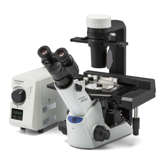
CKX53
Culture Microscope
Notes
Optical microscope and accessory
This instruction manual is for the Olympus culture microscope model CKX53.
To ensure the safety, obtain optimum performance and to familiarize yourself fully with the use of the
microscope, we recommend that you study this manual thoroughly before operating the microscope,
and always keep this manual at hand when operating the microscope.
Retain this instruction manual in an easily accessible place near the work desk for future reference.
For details of products included in the configuration of this system, see page 7.
A X 8 6 6 0
Advertisement
Table of Contents

Related Manuals for Olympus CKX53


Summary of Contents for Olympus CKX53
- Page 1 Notes Optical microscope and accessory This instruction manual is for the Olympus culture microscope model CKX53. To ensure the safety, obtain optimum performance and to familiarize yourself fully with the use of the microscope, we recommend that you study this manual thoroughly before operating the microscope, and always keep this manual at hand when operating the microscope.
- Page 2 Refer to your local Olympus distributor in EU for return and/or collection systems available in your country. NOTE: This product has been tested and found to comply with the limits for a Class A digital device, pursuant to Part 15 of the FCC Rules.
-
Page 3: Table Of Contents
Contents Introduction ............................... 1 Safety precautions ............................2 1 Nomenclature of units ........................7 2 Nomenclature of main operating portions ............... 8 2-1 Bright field set / Phase contrast entry set / Phase contrast standard set ..8 2-2 Fluorescence set ............................... 9 3 Observation procedures .........................10 3-1 Preparation of observation ........................10 Moving the microscope ................................ - Page 4 3-4 Observation method (Fluorescence observation)..............15 Inserting the shutter for reflected light illumination (Fluorescence set) ........15 Inserting the umbra shield (ambient light shielding plate) (Fluorescence set) ....15 Turning ON the light source (mercury burner) (Fluorescence set) ..........15 Inserting the fluorescence mirror unit (Fluorescence set) ..............16 Changing between the visual light path and the camera light path ...........
- Page 5 5-1 Bright field observation / Phase contrast observation ..........25 5-2 Fluorescence observation ........................26 5-3 Common in all observation methods................... 27 6 Specifications ............................28 6-1 Sets with CKX53 ............................. 28 6-2 Objective ................................30 6-3 Optional units ..............................30 6-4 Operating environment ..........................31 7 Assembly ..............................
- Page 6 7-3 Assembly of the fluorescence illuminator CKX3-RFA (Fluorescence set) ..34 7-4 Assembling the stage (Phase contrast standard set / Fluorescence set) ..38 7-5 Attaching the objectives ........................... 39 7-6 Attaching the phase contrast slider (Phase contrast entry set / Phase contrast standard set) .......... 40 7-7 Attaching the filter slider for transmitted light illumination ........
-
Page 7: Introduction
Read all the instruction manuals supplied with the units you purchased. The following instruction manuals are prepared for this product. Instruction manuals Main contents CKX53 (this document) Operation procedures of the microscope, etc. Mercury power supply unit Power supply unit of mercury lamp housing... -
Page 8: Safety Precautions
Safety precautions If the product is used in a manner not specified by this manual, the safety of the user may be imperiled. In addition, the product may also be damaged. Always use this product according to the instruction manual. The following symbols are used in this instruction manual. - Page 9 CKX53 CAUTION - Electric safety - Always use the AC adapter, the power cord and other cables provided by Olympus. If other AC adapters, power cords, or cables are used, the electric safety and the EMC (Electro-Magnetic Compatibility) performance of the product can not be assured. If no power cord is provided, please select the proper power cord by referring to the section “Proper selection of the power cord”...
- Page 10 • Mercury lamp housing [ High voltage ] [ High temperature ] U-LH100HG Caution display position • Power supply unit [ High voltage ] U-RFL-T When caution labels are dirty or peeled off, contact Olympus for replacement or inquiries.
- Page 11 Units of this product For units attachable to this product, see page 7. · Do not use a light source other than those recommended by Olympus. NOTE · The product in combination with other separately available camera may become unstable. Take the measures to prevent the product from tipping over.
- Page 12 U-RFL-T or light guide illumination system U-HGLGPS, wait until the lamp housing is cooled down sufficiently, and keep it covered with a dust cover during storage. Before disposing of this product, be sure to follow the regulations and rules of your local government. Contact Olympus for any questions.
-
Page 13: Nomenclature Of Units
· Units described below are units composing the CKX53 system including options. · There are other combinable units available. Please see latest brochures or ask Olympus. For the units marked with *, refer to a separate set of instruction manuals. -
Page 14: Nomenclature Of Main Operating Portions
Nomenclature of main operating portions 2-1 Bright field set / Phase contrast entry set / Phase contrast standard set ‡ Filter holder for transmitted light illumination Aperture iris diaphragm lever Condenser fixing knob Pre-centered phase contrast slider Revolving nosepiece Camera Adapter fixing knob Stage center plate Diopter adjustment... -
Page 15: Fluorescence Set
CKX53 2-2 Fluorescence set Umbra shield (ambient light shieldingplate) Field iris diaphragm centering knob Revolving nosepiece Camera Adapter fixing knob Main switch (back of light source) For details, see the instruction manual provided with U-HGLGPS. Collector lens focusing knob Mirror focusing screw... -
Page 16: Observation Procedures
Observation procedures 3-1 Preparation of observation Moving the microscope When carrying this microscope to a different location, remove all cables and units in advance. When using the Fluorescence set, remove the mercury lamp housing U-LH100HG or the liquid light guide adapter U-LLGAD from the fluorescence illuminator CKX3-RFA. -
Page 17: Cleaning And Sterilizing Around The Stage
CKX53 Useful information The AC adapter e can be hung on the hook f on the back of the microscope frame CKX53SF. Bundling the AC adapter cord g with the provided tie wrap clears the space on the back of the microscope frame. -
Page 18: When Using The High Container (Procedures To Attach / Detach The Condenser Portion)
When using the high container (Procedures to attach / detach the condenser portion) Hold the condenser portion with one hand. Loosen the condenser fixing knob with the other hand to remove it. Place the removed condenser portion on the level surface NOTE or place it with the lens surface facing up in order not to scratch the lens. -
Page 19: Adjusting The Aperture Iris Diaphragm
CKX53 Adjusting the aperture iris diaphragm Rotate the aperture iris diaphragm lever to adjust the aperture iris diaphragm. : indicates the opening direction : indicates the closing direction · For the phase contrast observation, set the aperture iris diaphragm lever to the open side ( ). -
Page 20: Focusing On The Specimen
Focusing on the specimen Rotate the coarse focusing knob a or the fine focusing knob b to bring the specimen into focus. Rotation direction of coarse focusing knob and fine focusing knob Rotating either knob in the front direction (arrow direction) raises the objective and rotating it in the opposite direction lowers the objective. -
Page 21: Observation Method (Fluorescence Observation)
CKX53 3-4 Observation method (Fluorescence observation) For safety when performing the fluorescence observation, be sure to follow cautions described in CAUTION "CAUTION - Illumination light for fluorescence observation -"(page 3) and "CAUTION - Mercury lamp housing -"(page 4). Inserting the shutter for reflected light illumination (Fluorescence set) Hold and slide the knob of the filter slider for reflected light illumination and engage the shutter of the slider in the light path. -
Page 22: Inserting The Fluorescence Mirror Unit (Fluorescence Set)
Inserting the fluorescence mirror unit (Fluorescence set) Hold and slide the fluorescence mirror unit selection lever a of the fluorescence illuminator CKX3-RFA and engage the fluorescence mirror unit to be used for observation in the light path. · When adjusting the field iris diaphragm (see page 21), engage the B-excitation fluorescence mirror unit in the light path. -
Page 23: Recording With The Camera
CKX53 3-5 Recording with the camera The observed image can be acquired by attaching the camera adapter and the camera to the camera port of the microscope frame CKX53SF. Changing between the visual light path and the camera light path... -
Page 24: Cleaning Up
3-6 Cleaning up Cleaning up the fluorescence illuminator (Fluorescence set) Hold and slide the knob of the filter slider for reflected light illumination and engage the shutter of the slider in the light path. Hold and slide the selection lever of the fluorescence mirror unit slider and engage the fluorescence mirror unit placed at the center of the slider in the light path. -
Page 25: For Advanced Observation
CKX53 For advanced observation 4-1 Adjusting the binocular portion ・When operating the binocular portion, adjust the operation force level so that the microscope frame NOTE CKX53SF does not move. Adjusting the interpupillary distance While looking through the eyepieces, move the binocular portion until the left and right fields of view coincide completely. -
Page 26: Adjusting The Tension Of The Coarse Focusing Knob
4-2 Adjusting the tension of the coarse focusing knob The tension of the coarse focusing knob can be adjusted. Insert the tip of a large flat-blade screwdriver into the groove b on the tension adjustment ring a and rotate the ring. Rotating the coarse focusing knob in the arrow direction shown in the picture increases the tension and rotating it in the opposite direction decreases the tension respectively. -
Page 27: Adjusting The Field Iris Diaphragm In Fluorescence Observation (Fluorescence Set)
CKX53 4-5 Adjusting the field iris diaphragm in fluorescence observation (Fluorescence set) Hold and slide the selection lever of the fluorescence mirror unit slider and engage the B-excitation fluorescence mirror unit in the light path. Hold and slide the knob of the filter slider for reflected light illumination and engage the empty hole of the slider in the light path. -
Page 28: Centering Of The Centering Phase Contrast Sider Ix2-Sl (Option)
4-7 Centering of the centering phase contrast sider IX2-SL (option) When performing the phase contrast observation using the PHL phase contrast ring of the centering phase contrast slider IX2-SL or the PH1 phase contrast ring IX2-SLPH1, the centering of the phase contrast ring must be performed. -
Page 29: Operating Procedures Of Ckx3-Slpic (Option)
CKX53 4-9 Operating procedures of CKX3-SLPIC (option) Combining the IC ring slit CKX3-SLPIC with the objective (PLCN10X or CACHN10XIPC) enables to perform the IC observation. The IC observation is featured that the contrast of the observed image is reversed depending on the focal point of the specimen. -
Page 30: Selecting Procedures Of The Fluorescence Mirror Unit (Including Options)
4-11 Selecting procedures of the fluorescence mirror unit (including options) Selecting the fluorescence mirror unit (Fluorescence set) Referring to the followings, select the fluorescence mirror unit to be used for observation. · The fluorescence illuminator CKX3-RFA contains the B-excitation fluorescence mirror unit and the G-excitation fluorescence mirror unit as a standard mirror unit. -
Page 31: Troubleshooting
Depending on how you use, the performance of the microscope may not be exhibited properly. If problems occur, please review the following list and take remedial action as needed. If you cannot solve the problem after checking the entire list, please contact Olympus for assistance. 5-1 Bright field observation / Phase contrast observation... -
Page 32: Fluorescence Observation
5-2 Fluorescence observation Problem Cause Remedy Page 1. Even though the The power cord or connectors are not Connect the power cord or connectors main switch is set to connected firmly. firmly. " " (ON), the mercury The mercury burner is not attached. Attach a mercury burner. -
Page 33: Common In All Observation Methods
If you cannot solve the problems even though taking actions described in "5 Troubleshooting ", please contact Olympus for assistance. At that time, please tell them the following information as well. · Product name and abbreviation (Ex. : microscope frame CKX53SF) ·... -
Page 34: Specifications
Specifications 6-1 Sets with CKX53 Item Specifications Bright Field Set Phase Contrast Phase Contrast Fluorescence Set Entry Set Standard Set Optical system UIS2 optical system Applicable observation method Bright field Bright field, Phase contrast Bright field, Phase contrast, Fluorescence Dimensions (D x W x H) - Page 35 CKX53 Item Specifications Bright Field Set Phase Contrast Phase Contrast Fluorescence Set Entry Set Standard Set Others AC adapter holder (on the back of microscope frame) Transport hand grip (on the back of microscope frame) Desktop sliding pad Accessories Cable holder : 2 pieces...
-
Page 36: Objective
6-2 Objective W.D. Phase contrast IC (Inversion Fluorescence Objective (applicable ring) contrast) B-excitation G-excitation U-excitation PLN2X 0.06 PLCN4X 18.5 PLCN10X 0.25 10.6 ¦ UPLFLN4XIPC 0.13 16.4 Provided with ¦ ¦ ¦ CKX3-SLP CACHN10XIPC 0.25 Provided with ¦ ¦ ¦ CKX3-SLP LCACHN20XIPC Provided with ¦... -
Page 37: Operating Environment
CKX53 Item Specifications 76.6x26.6 mm (Ø48 mm) b Slide glass holder Ø54 (Ø48 mm) IX-HOS 81.5x56 mm (88x46 mm) c Terasaki plate holder Ø65 mm (Ø58 mm) IX-HOT 77x35 mm (Ø58 mm) d Blood cell test plate Ø65 mm (Ø58 mm) holder IX2-BCTP Ø38.5 (Ø30 mm) -
Page 38: Assembly
Assembly 7-1 Assembly diagram The following diagram shows the units before assembly. The chapters describing the procedure to attach each unit are shown in frames with dotted lines. Before assembly, remove dust and dirt from the attaching portions of each unit and assemble carefully NOTE so as not to scratch units. -
Page 39: Assembly Of The Microscope Frame Ckx53Sf
CKX53 7-2 Assembly of the microscope frame CKX53SF Attaching the condenser portion Loosen the condenser fixing knob a to the extent that it does not fall off. Hold the condenser diagonally, contact the attaching portion on the top surface b of the condenser to the round dovetail portion on the bottom of the column and fit it. -
Page 40: Assembly Of The Fluorescence Illuminator Ckx3-Rfa (Fluorescence Set)
7-3 Assembly of the fluorescence illuminator CKX3-RFA (Fluorescence set) Attaching the fluorescence mirror unit ・When attaching or detaching the fluorescence mirror unit, CAUTION set the main switch of the light source for reflected light illumination to (OFF) in advance. ・Be sure to attach the empty mirror unit for bright field ob- servation. - Page 41 CKX53 Attaching the fluorescence illuminator CKX3-RFA Remove the objective from the revolving nosepiece. Rotate the coarse focusing knob and place the revolving nosepiece at the upper limit position. Peel off the stickers (2 positions) from the dust cover surface of the microscope frame CKX53SF.
- Page 42 Insert the screws a which secured the dust cover into the holes (2 positions) g of the frame side part, and tighten them with the Allen wrench to secure to the microscope frame. Detach the the filter slider for reflected light illumination from the light source side part e .
- Page 43 At this time, face the surface where "ND25 " is printed up. ・· Do not use attenuator filters other than those provided and those (option) recommended by Olympus. Attaching the filter slider for reflected light illumination Remove the stopper d fixed to the filter slider for reflected light illumination using the Allen screwdriver.
-
Page 44: Assembling The Stage (Phase Contrast Standard Set / Fluorescence Set)
Attaching the umbra shield (ambient light shielding plate) Remove the condenser portion from the microscope frame CKX53SF. For procedures to remove the condenser portion, see page 33. Loosen the umbra shield knob a . Insert the tip of the umbra shield column into the screw hole of the condenser portion, and insert the Allen screwdriver in the hole of the column b to tighten it and secure the column. -
Page 45: Attaching The Objectives
CKX53 Attaching the mechanical stage CKX3-MVR When using the mechanical stage CKX3-MVR, we recommend you to use it in combination with the sub stage CK2-SS to exhibit its full performance Attaching the frame portion Attaching the mechanical stage CKX3-MVR to the plain stage allows you to move the container on the stage using the knob of the mechanical stage. -
Page 46: Attaching The Phase Contrast Slider (Phase Contrast Entry Set / Phase Contrast Standard Set)
7-6 Attaching the phase contrast slider (Phase contrast entry set / Phase contrast standard set) Attaching the pre-centered phase contrast slider CKX3-SLP Set the pre-centered phase contrast slider CKX3-SLP a with the surface where the texts are described facing up, and insert it in the pre-centered phase contrast slider hole b of the condenser portion. -
Page 47: Attaching The Filter Slider For Transmitted Light Illumination
CKX53 7-7 Attaching the filter slider for transmitted light illumination Take out the filter holder for transmittedlight illumination a , and insert the necessary filter b . 7-8 Attaching the light source for reflected light illumination (Fluorescence set) Attaching the mercury burner... - Page 48 ・Align the external edges of the lamp housing with those CAUTION on the socket part, and push the lamp housing straight downward. ・Attach the lamp housing on the lamp housing attaching position of the microscope so that the heat radiating fins face upward, and secure the sufficient space around the top surface, lower surface and the back surface.
- Page 49 CKX53 Centering the mercury burner (only when combined with the mercury lamp housing U-LH100HG ) The mercury burner emits the light by means of discharge produced when a current is supplied across the poles. If the positions of the poles were moved for example during replacement of the burner, the brightness of the light would be uneven.
- Page 50 Turn the collector lens focusing knob to project the arc image on the white paper placed on the stage. (A in the picture) If the arc image is not projected, turn the burner centering knobs. Turn the burner centering knobs to bring the arc image on the center of the right (left) half of the field.
-
Page 51: Attaching The Camera
CKX53 7-9 Attaching the camera Attaching the camera adapter Refer to the instruction manual for the camera adapter in use. Attaching the camera Refer to the instruction manual for the camera adapter in use. Wiring the camera cable The cable wiring needs the clamping screw (2 pcs.) a provided with the microscope frame CKX53SF and the cable holder (2 pcs.) b... -
Page 52: Preventive Inspection Sheet For Illumination Devices
· If there are any check marks ( ) noted, immediately stop use of the product and seek service or replacement for the illumination device(s) for prevention. · If you detect an abnormality other than that listed below with your illumination device or other Olympus product, request inspection from Olympus. -
Page 53: Appendix
CKX53 Appendix 9-1 Summary of procedures of bright field observation / phase contrast observation Preparation • Attach the objectives suitable for observation methods. • Attach the pre-centered phase contrast slider CKX3-SLP (for phase contrast observation). (Operation portion) (Page) Observation Procedures... -
Page 54: Summary Of Fluorescence Observation Procedures
9-2 Summary of fluorescence observation procedures Preparation • Attach the objectives suitable for observation methods. • Centering of the mercury burner (when using the mercury lamp housing U-LH100HG) Observation Procedures (Operation portion) (Page) Turn ON the main switch of the power supply unit and Main switch (page 15) wait until the arc image is stabilized (5 to 10 minutes). - Page 55 If no power cord is provided, please select the proper power cord for the product by referring to “Specifications” and “Certified Cord” below: Caution : In case you use a non-approved power cord for Olympus products, Olympus can no longer warrant the electrical safety of the product.
- Page 56 Table 2 HAR flexible cord Approval organizations and cordage harmonization marking methods Alternative marking utilizing Printed or embossed black-red-yellow thread (Length harmonization marking (May be of color section in mm) Approval organization located on jacket or insulation of internal wiring) Black Yellow Comite Electrotechnique Belge...
- Page 57 Memo...
- Page 58 Memo...
- Page 60 Manufactured by Shinjuku Monolith, 2-3-1 Nishi-Shinjuku, Shinjuku-ku, Tokyo 163-0914, Japan Distributed by 48 Woerd Avenue Waltham, MA 02453, U.S.A. 8F Olympus Tower, 446 Bongeunsa-ro, Gangnam-gu, Seoul, 06153 Korea AX8660 06...
Need help?
Do you have a question about the CKX53 and is the answer not in the manual?
Questions and answers