Table of Contents
Advertisement
INSTRUCTIONS
BXFM
FOCUSING UNIT
This instruction manual is for the Olympus Focusing Unit model BXFM and associated modules.
To ensure safety, optimum performance and familiarize yourself fully with the use of the assembled
microscope, we recommend that you study this manual thoroughly before operating the unit. Re-
tain this instruction manual in an easily accessible place near the work desk for future reference.
A X 7 6 1 3
This publication is printed on 100% recycled paper
Advertisement
Table of Contents

Subscribe to Our Youtube Channel
Related Manuals for Olympus BXFM Series


Summary of Contents for Olympus BXFM Series
- Page 1 BXFM FOCUSING UNIT This instruction manual is for the Olympus Focusing Unit model BXFM and associated modules. To ensure safety, optimum performance and familiarize yourself fully with the use of the assembled microscope, we recommend that you study this manual thoroughly before operating the unit. Re- tain this instruction manual in an easily accessible place near the work desk for future reference.
-
Page 3: Table Of Contents
BXFM CONTENTS Correct assembly and adjustments are critical for the microscope to exhibit its full performance. If you are going to assemble the microscope yourself, please read chapter 10, “ASSEMBLY” (pages 24 to 27) carefully. IMPORTANT — Be sure to read this section for safe use of the equipment. — SYSTEM DIAGRAM NOMENCLATURE REFLECTED LIGHT BRIGHTFIELD OBSERVATION PROCEDURE... - Page 4 ” (OFF) and unplug the power cord before replacing the light source bulb. (P. 26) 7. Always use the power cord provided by Olympus. If no power cord is provided, please select the proper power cord by referring to the chapter Fig.
- Page 5 BXFM 9. When using a photographic unit or TV camera, be sure to observe the total weight limit of the modules added to the standard combination as shown below. Illuminator BXFM-ILH BXFM-ILHS Mounting Holder 5.2 kg 7.5 kg Standard Combination U-KMAS, U-TR30-2, BX-RLA2, U-TR30-2, Weight (Module...
- Page 6 Getting Ready 1. A microscope is a precision instrument. Handle it with care and avoid subjecting it to sudden or severe impact. 2. Do not use the microscope system where it is subjected to direct sunlight, high temperature and humidity, dust or vibrations.
- Page 7 BXFM SYSTEM DIAGRAM }This instruction manual gives description the modules which are connected in thick and broken lines in the following diagram. For other modules, please refer to their instruction manuals. ** For the modules without the model names, consult your dealer or the latest catalogues. * Reflected Light Lamp Housing Halogen bulb: U-LH100-3...
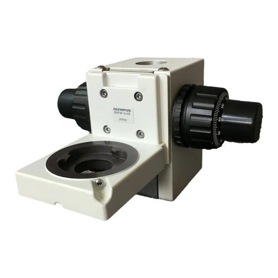
- Page 8 NOMENCLATURE Focusing Unit BXFM-F Coarse adjustment knob Pillar mounting hole Fine adjustment knob ( 32 mm) Rubber fine adjustment knob cap Fine adjustment knob Coarse adjustment knob Coarse adjustment knob tension adjustment ring BXFM-ILHSPU counter spring mounting screw hole Auxiliary centering screws* * Used when the BX-RLA2 or BX-URA2 illuminator is combined with the focusing unit.
- Page 9 BXFM Illuminator Holder BXFM-ILH, Counter Spring BXFM-ILHSPU }The BX-URA2 or BX-RLA2 reflected light illuminator can be installed. The BXFM-ILHSPU is used to reduce the load on focusing due to the weight of the reflected light illuminator and its accessories. Mounting holes x 4 Illuminator mount screw holes Stand U-ST Power Supply TH4...
- Page 10 REFLECTED LIGHT BRIGHTFIELD OBSERVATION PROCEDURE }The following flow chart pertains only to the reflected light brightfield observation which is the most basic operation. The procedures for the polarized light and Nomarski DIC operations will be described in their respective sections. (Controls Used) (Page) @Main switch...
- Page 11 BXFM Trinocular Tube U-TR30-2 Halogen Lamp Housing † U-LH100-3 Compact Reflected Light Brightfield Illuminator U-KMAS … Š ³ ‡ ³ Power Supply Focusing Unit BXFM-F ² Hand Switch ƒ TH4-HS Stand U-ST } Make a photocopy of the observation procedure pages and post it near your microscope.
-
Page 12: Using The Controls
USING THE CONTROLS 4-1 Base and Power Supply Voltage Indication (Figs. 3 & 4) 1. Ensure that the brightness control knob @ is set to MIN (lowest voltage) then set the main switch ² to “ I ” (ON). (The POWER LED ³ lights.) 2. -
Page 13: Focusing Unit
BXFM 4-2 Focusing Unit Adjusting the Coarse Adjustment Knob Tension (Fig. 6) ² }The rotation tension of the coarse adjustment knob should be adjusted using the tension adjustment ring. The coarse adjustment knob tension is preadjusted for easy use. However, if desired, you can change the tension using the tension adjustment ring @. -
Page 14: Observation Tube
4-3 Observation Tube Adjusting the Interpupillar Distance (Fig. 8) While looking through the eyepieces, adjust for binocular vision until the left and right fields of view coincide completely. The index dot · indicates the interpupillary distance. }Note your interpupillary distance so that it can be quickly duplicated. Fig. -
Page 15: Using Eyepiece Micrometer Disks
BXFM Using Eyepiece Micrometer Disks (Fig. 12) Eyepiece micrometer disks can be inserted into WHN10X-H (or WHN10X) eyepieces. However, if the eyepiece does not have the helicoid adjustment facility and your eyesight is poor, you may have difficulties in focusing on the ²... -
Page 16: Reflected Light Illuminator (U-Kmas)
4-4 Reflected Light Illuminator (U-KMAS) Using the Filters (Fig. 15) }Engage the optimum filter sliders for the purpose of observation in the two filter insertion slots @. Be sure to insert them in the direction shown in Fig. 15. The first click position is the idle position and the second click engages the filter in the light path. -
Page 17: Observation Methods (Using U-Kmas)
BXFM OBSERVATION METHODS (Using U-KMAS) }For the observation methods of the BX-URA2 and BX-RLA2 reflected light illuminators, refer to their instruction manuals. 5-1 Reflected Light Brightfield Observation See “REFLECTED LIGHT BRIGHTFIELD OBSERVATION PROCEDURE” on page 7. 5-2 Reflected Light Nomarski DIC (Differential Interference Contrast) Observation # The performance of polarizer may deteriorate when it has been exposed to light for a long period (about continu- ous 2000 hours). - Page 18 Setting the DIC Slider (Fig. 18) ² 1. Loosen the mounting knob @ on the front of the DIC revolving nosepiece, insert the DIC slider ² so that the surface with indication faces up, and clamp by tightening the mounting knob. 2.
-
Page 19: Reflected Light Simplified Polarized Light Observation
BXFM U-DICRH 1. Adjust the background contrast by turning the prism movement knob | on the DIC slider as described below. (Fig. 18) 2. When the prism movement knob on the U-DICRH DIC slider is turned, the interference color in the background varies from -100 to 100 nm. Set the retardation which can provide best contrast. -
Page 20: Troubleshooting Guide
Under certain conditions, performance of the unit may be adversely affected by factors other than defects. If problems occur, please review the following list and take remedial action as needed. If you cannot solve the problem after checking the entire list, please contact your local Olympus representative for assistance. Problem... - Page 21 BXFM Problem Cause Remedy Page 4. Electrical System a) Bulb intermittently lights and goes Bulb is near the end of service life. Replace bulb. out. A cord or connector is not properly con- Connect cords and plugs securely. nected. b) LED lights but lamp bulb does not. Bulb is burnt out. Replace bulb.
-
Page 22: Specifications
SPECIFICATIONS Item Specification Optical system UIS2 (UIS) (Universal Infinity System) optical system Reflected light illumination Tube magnification 1X, super widefield (FN 26.5) compatible. (U-KMAS illuminator) Available observations: @ Reflected light brightfield ² Reflected light Nomarski DIC ³ Reflected light simplified polarized light Electrical system 12V, 100W long-life halogen bulb (pre-centered) 12V100WHAL-L (PHILIPS 7724) (U-LH100-3 lamp housing, TH4... -
Page 23: Main Dimension Diagram
BXFM MAIN DIMENSION DIAGRAM Focusing Unit BXFM-F Provided with Illuminator Mounting Holder S BXFM-F + BXFM-ILHS... - Page 24 Provided with Illuminator Mounting Holder/Counter Spring BXFM-F + BXFM-ILH + BXFM-ILHSPU...
-
Page 25: Optical Characteristics "Uis2 (Uis) Series
(as shown in the diagram on the right). UIS marking NA (Numerical Aperture) NOTE Brightfield/darkfield Refer to the latest catalogue or consult Olympus for the updated infor- application mation on the eyepieces and objectives that can be combined with this unit. Cover glass thickness FN (Field Number) —: May be used with our with-... - Page 26 Significance of Objective Name (Examples) (Plan) None : Brightfield : Darkfield BDP : Brightfield or polarized : IR light Figure : Magnification None : UIS : UIS 2 None : Achromat, or aberration correction with 2 wavelengths (red and bleu). : Semi-Apochromat, or color aberration correction with visual wave- lengths (bluish purple to red).
-
Page 27: Assembly
· The module numbers shown in the following diagram are merely the typical examples. For the modules with which the module numbers are not given, please consult your Olympus representative or the catalogues. # When assembling the microscope, make sure that all parts are free of dust and dirt, and avoid scratching any parts or touching glass surfaces. - Page 28 10-2 Detailed Assembly Procedures Attaching the Illuminator Holder (Fig. 19) Attach the illuminator holder @ on the focusing unit ² securing by using the 4 screws provided with the holder and the Allen screwdriver. }To obtain the reference position, clamp the illuminator holder by applying it against the bottom and right side.
- Page 29 BXFM Attaching the Eyepiece (Fig. 23) Gently insert the eyepiece all the way into each eyepiece sleeve. # When using the U-BI30-2 binocular tube, eyepieces with built-in mi- crometer disk cannot be attached. # When using a finder eyepiece or an eyepiece with micrometer disk, attach it to the right-hand eyepiece sleeve.
- Page 30 1. Insert the hand switch plug @ into the connector ². 2. Insert the lamp housing plug ³ into the connector |. Always use the power cord provided by Olympus. IF no power cord ³ is provided with the microscope, please select the proper power cord by referring to chapter “PROPER SELECTION OF THE POWER...
-
Page 31: Proper Selection Of The Power Supply Cord
If no power supply cord is provided, please select the proper power supply cord for the equipment by referring to “ Specifications ” and “ Certified Cord ” below: CAUTION: In case you use a non-approved power supply cord for Olympus products, Olympus can no longer warrant the electrical safety of the equipment. - Page 32 Table 2 HAR Flexible Cord APPROVAL ORGANIZATIONS AND CORDAGE HARMONIZATION MARKING METHODS Alternative Marking Utilizing Printed or Embossed Harmoniza- Black-Red-Yellow Thread (Length tion Marking (May be located on Approval Organization of color section in mm) jacket or insulation of internal wir- ing) Black Yellow...
- Page 33 MEMO...
- Page 34 MEMO...
- Page 36 Shinjuku Monolith, 3-1, Nishi Shinjuku 2-chome, Shinjuku-ku, Tokyo, Japan Wendenstraße 14-18, 20097 Hamburg, Germany 3500 Corporate Parkway, P.O. Box 610, Center Valley, PA 18034-0610, U.S.A. One Corporate Drive, Orangeburg, NY 10962, U.S.A. 491B River Valley Road, #12-01/04 Valley Point Office Tower, Singapore 248373 31 Gilby Road, Mount Waverley, VIC., 3149, Australia 5301 Blue Lagoon Drive, Suite 290 Miami, FL 33126, U.S.A.
Need help?
Do you have a question about the BXFM Series and is the answer not in the manual?
Questions and answers