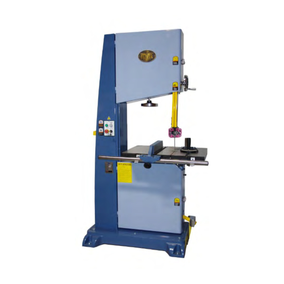
Summary of Contents for Oliver 4650
- Page 1 4650 22” Bandsaw Owner’s Manual Oliver Machinery M-4650 10/2011 Seattle, WA Copyright 2003 info@olivermachinery.net www.olivermachinery.net...
-
Page 2: Warranty
Oliver makes every effort possible to assure that its equipment meets the highest possible standards of quality and durability. All products sold by Oliver are warranted to the original customer to be free from defects for a period of 2 (two) years on all parts, excluding electronics and motors, which are warranted for 1 year. - Page 3 WARNING Read this manual completely and observe all warning labels on the machine. Oliver Machinery has made every attempt to provide a safe, reliable, easy-to-use piece of machinery. Safety, however, is ultimately the responsibility of the individual machine operator. As with any piece of machinery, the operator must exercise caution, patience, and common sense to safely run the machine.
- Page 4 15. Misuse: Do not use this Oliver bandsaw for other than its intended use. If used for other purposes, Oliver disclaims any real or implied warranty and holds itself harmless for any injury or damage which may result from that use.
-
Page 5: Table Of Contents
Maintenance ..............................13 Lubrication ..............................13 Troubleshooting ............................14 Specifications Model No.............. 4650 Stock No............... 4650.001 (5HP, 1Ph) ................4650.002 (5HP, 3Ph) Blade Speed (SFPM) ........... 4,000 Wheel Diameter (in.) ..........20 Table Dim. (WxL/in.) ..........26-3/4 x 20-1/2 Throat Distance (in.) .......... -
Page 6: Warnings
Contents of the Shipping Containers Picture 2 1. Fence 2. Rail 3. Miter guage 4. Rail brackets 5. Speed handle 6. Wrenches 7. Allen keys 8. Rail mounting hardware 9. Measuring tape for rail 10. Eye bolts 11. Tray Uncrating the Machine Your bandsaw should arrive crated as shown in Picture 1. -
Page 7: Dust Chute Assembly
Fence Assembly 1. Disconnect machine from power source. 2. Install rail brackets (A, Figure 1) to the table as shown using the supplied hardware. See inset B and notice the elongated hole of the bracket mates with the edge of the table Do not fully tighten at this time. -
Page 8: Installing Blade
Installing Blade WARNING Bandsaw blades are sharp so be very careful while handling. Failure to comply may cause serious injury! 1. Disconnect machine from power source. 2. Open upper and lower doors. 3. Remove fence and fence rail. 4. Remove table pin (A, Figure 5). 5. -
Page 9: Blade Tracking
Blade Tracking require you to perform Adjustment 3 before Adjustment 2. Blade tracking has been adjusted at the factory Adjustment 1 and shouldn’t need any adjustment. If you are experiencing a problem follow the below listed 1. Blade tension and tracking must be properly steps. -
Page 10: Adjusting Lower Blade Guides
Adjusting the Blade Guides (cont.) Adjusting the Lower Blade Guide The lower blade guide adjusts in the same way Adjustment 2 as the upper however Adjustment 2 is achieved by loosening the set screw (Figure 10). 1. Blade guides ‘B’ and ‘C’ of Figure 8 need to be positioned to just behind the blade gullet as The rear blade support bearing Adjustment 3 is shown by ‘D’... - Page 11 Squaring Table to the Blade 1. Disconnect machine from power source. 2. Blade tension, tracking and guide setup must be properly adjusted prior to squaring the table to the blade, see “Tensioning Blade” page 8, “Blade Tracking” page 9, “Adjusting Upper Blade Guides” page 9 and “Adjusting Lower Blade Guides”...
-
Page 12: Electrical Connections
Electrical Connections Electrical Connections for a 1-Phase Unit This bandsaw is 1-Phase, 220V only. Oliver WARNING Machinery recommends using a dedicated Electrical connections and wiring must be circuit. done by a qualified electrician. The machine must be properly grounded. Failure to... -
Page 13: Maintenance
Maintenance If tilting the table frequently, clean off the table tilt trunions and apply a white lithium grease to the friction points. WARNING Disconnect the machine from power source before proceeding with any maintenance! Failure to comply may cause serious injury! Periodically clean the inside of the machine for dust control. -
Page 14: Troubleshooting
Troubleshooting WARNING Disconnect the machine from power source before proceeding with any troubleshooting! Failure to comply may cause serious injury! Description of Symptoms Possible Cause Corrective Action 1. Fuse blown or circuit breaker 1. Replace fuse or reset circuit tripped breaker 2.


Need help?
Do you have a question about the 4650 and is the answer not in the manual?
Questions and answers