Table of Contents

Related Manuals for Oliver 4035


Summary of Contents for Oliver 4035
- Page 1 4035 12” Professional Tablesaw Owner’s Manual Oliver Machinery M-4035 03/2007 1210 Andover Park East © Copyright 2003 Tukwila, WA 98188 Fax: 1-206-575-2723 www.olivermachinery.net Phone: 1-206-575-2722 email: info@olivermachinery.net...
-
Page 2: Warranty
Oliver makes every effort possible to assure that its equipment meets the highest possible standards of quality and durability. All products sold by Oliver are warranted to the original customer to be free from defects for a period of 2 (two) years on all parts, excluding electronics and motors, which are warranted for 1 year. -
Page 3: Warnings
WARNING Read this manual completely and observe all warning labels on the machine. Oliver Machinery has made every attempt to provide a safe, reliable, easy-to-use piece of machinery. Safety, however, is ultimately the responsibility of the individual machine operator. As with any piece of machinery, the operator must exercise caution, patience, and common sense to safely run the machine. -
Page 4: Dust Port Diameter (In)
Misuse: Do not use this Oliver tablesaw for other than its intended use. If used for other purposes, Oliver disclaims any real or implied warranty and holds itself harmless for any injury or damage which may result from that use. -
Page 5: Table Of Contents
Replacing the Blade...........................15 Replacing and Tensioning the Drive Belt....................16 Maintenance..............................16 Troubleshooting............................17-18 Specifications Model Number............................4035 Blade Diameter (In)............................12 Arbor Diameter (In)........................5/8" OR 1” Maximum Depth of Cut at 90 Degrees (In)....................4" Maximum Depth of Cut at 45 Degrees (In)...................2-2/3" Maximum Cut to the Right of Blade......................36”... -
Page 6: Contents Of The Shipping Containers
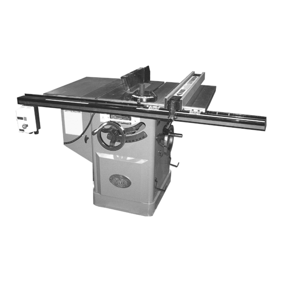
Contents of the Shipping Containers Oliver 4035, 12” Professional Tablesaw Once the top is removed the saw will be as shown with the left extension wing already attached. Inspect for freight damage and call the freight carrier if any. Contents Blade guard 2. -
Page 7: Machine Preparation And Setup
Machine Preparation and Setup WARNING! The equipment used to lift this machine must have a rated capacity at, or above the weight of the tablesaw. Failure to comply may cause serious injury! The tablesaw must be positioned on a smooth, level surface. -
Page 8: Rail Assembly
Rail Assembly 1. Rest the front guide support bracket on the switch box as shown in Figure 4 and secure into place using the chamfered bolts, nuts and washers provided in hardware packet 7. Note that the two outside holes require a nut and washer as well as a bolt while the four inside holes require the bolts only. -
Page 9: Fence Assembly And Adjustment
Fence Assembly and Adjustment 1. Place the fence on the guides as shown in Figure 7. Look for the rubber nib on the underside of the fence as shown and make sure it lines up with the back support rail. 2. -
Page 10: Adjusting The Scale Reader
Adjusting 45° and 90° Stops The stops have been adjusted at the factory and should not need any adjustment. If you need to adjust the stops: 1. Disconnect saw from power source. 2. Raise the saw blade to its maximum height by turning the blade raising handwheel clockwise as far as it will go. - Page 11 Adjusting 45° and 90° Stops (cont.) Set the blade 45° to the table by turning the blade tilting handwheel counter-clockwise as far as it will go. Place a combination square on the table and check to see that the blade is at a 45°...
-
Page 12: Leveling Table Insert
Leveling Table Insert Adjust the table insert flush with the table by turning the four leveling screws (C, Figure 16). Place a straight edge across the table and insert. Raise the insert until it just touches the straight edge. Check both the front and rear section of the insert. - Page 13 Splitter and Blade Guard Assembly (cont.) 9. Place a straight edge against the splitter and blade to make sure they align, as shown in Figure 20. If adjustment is necessary use the provided wrench to loosen the jam nut (E, Figure 21) on the rear fork.
-
Page 14: Miter Gauge
Miter Gauge 1. Slide the miter gauge bar into the miter gauge slot in table. Loosen the handle (A, Figure 23) and pull out indexing rod (B, Figure 23) to pivot the miter gauge body. 2. Push the indexing rod in to engage the preset stops (C, Figure 23). -
Page 15: Electrical Connections
220V. If you need to switch the tablesaw from 220V to 440V have a qualified electrician make the changes. Oliver Machinery recommends using a dedicated circuit. Make sure the voltage of your power supply matches the specifications on the motor plate of the machine. -
Page 16: Replacing And Tensioning The Drive Belt
Replacing and Tensioning V-Belt 1. Disconnect saw from power source. 2. Lower the blade to its lowest position and open the motor cover door. 3. Loosen the hex nut (B, Figure 26). 4. Take tension off of the belt (A, Figure 26) by lifting up on the motor. -
Page 17: Troubleshooting
Troubleshooting Description of Symptoms Possible Cause Corrective Action 1. Fuse blown or circuit breaker 1. Replace fuse or reset circuit tripped breaker 2. Cord Damaged 2. Have cord replaced 3. Faulty switch 3. Replace switch 4. Not connected to power 4. - Page 18 1. Reposition on flat, level 1. Stand on uneven floor surface 2. Damaged saw blade 2. Replace saw blade 3. Bad V-belts 3. Replace V-belts Saw vibrates excessively 4. Bent pulley 4. Replace pulley 5. Improper motor mounting 5. Check and adjust motor 6.
- Page 20 4035 Key Part # Descriptions Specifications Qty Cross Index 920660-000 Spreader Ass'y TJ0106 1.1 170584-904 Spreader Plate TJ010001 1.2 310018-909 Supporting Slot TJ010003 1.3 310019-909 Aluminium Support Plate TJ010005 1.4 160023-901 Spacer TJ010002 1.5 310020-909 TJ010006 Blade Side Guard 1.6 170586-904...
- Page 21 4035 Key Part # Descriptions Specifications Qty Cross Index .18 250483-615 Connecting Board Cap RTH160203 .19 310083-909 Fence Connecting Board RTH160202 .20 171423-308 Fence RTH160201 .21 048701-101 Square Screw M8*1.25P*20 TH050023 .22 006001-054 Flat Washer 8.5*20*2t HE014500 .23 008015-100 M8*1.25P(12B*6.5H)
- Page 22 4035 Key Part # Descriptions Specifications Qty Cross Index 19 240049-000 Hand Wheel TH120065 20 000002-101 M6*1.0P*12 HA010405 Hex Screw 21 000103-108 CAP Screw M6*1.0P*25 HA020413 22 011004-102 Spring Pin 6*20 HG011111 23 000104-108 CAP Screw M8*1.25P*25 12 HA020513 24 360476-901...
- Page 23 4035 Key Part # Descriptions Specifications Qty Cross Index 62 006001-001 Flat Washer 4.3*10*1.0t HE010600 63 390011-000 Saw Blade TJ010063 64 380480-901 Flange TJ010064 65 380479-902 Main Shaft Pulley TJ020003 66 050347-000 Lifting Support TJ010061 67 360471-000 Support Arbor TJ010067...
- Page 24 4035 Key Part # Descriptions Specifications Qty Cross Index 105 011002-106 Spring Pin 4*25 HG010914 106 000102-103 CAP Screw M5*0.8P*10 HA020304 107 021801-000 Retaining Ring Bolt NB-1722 HP200100 108 006502-100 BW-5 Lock Washer 5.3*10(BW-5) HE040800 109 000303-103 M5*0.8P*10 HA040604 Rounf HD Phil. Screw...
Need help?
Do you have a question about the 4035 and is the answer not in the manual?
Questions and answers