
Related Manuals for Oliver 4685


Summary of Contents for Oliver 4685
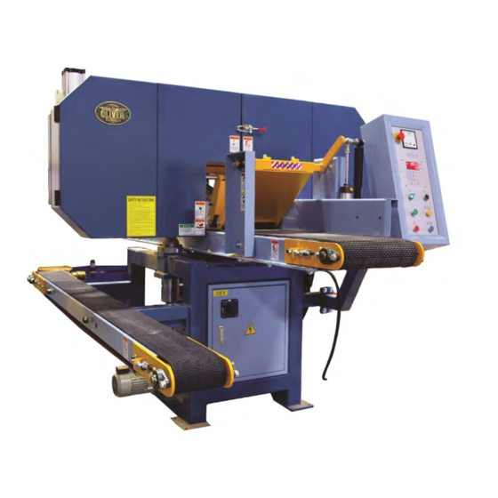
- Page 1 4685 Horizontal Band Resaw Owner’s Manual Oliver Machinery M-4685 10/2013 Seattle, WA Copyright 2013-2017 info@olivermachinery.net www.olivermachinery.net...
- Page 2 Oliver makes every effort possible to assure that its equipment meets the highest possible standards of quality and durability. All products sold by Oliver are warranted to the original customer to be free from defects for a period of 2 (two) years on all parts, excluding electronics and motors, which are warranted for 1 year.
- Page 3 WARNING Some dust created by power sanding, sawing, and grinding, drilling, and other construction activities contains chemicals known to the State of California to cause cancer, birth defects or other reproductive harm. Some examples of these chemicals are: • Lead from lead-based paints. •...
- Page 4 Specifications Model HP-400P HORIZONTAL RE-SAW BAND SAW Max. Workpiece Size 250mm(W) x 250mm(H)(10"x10") 400mm(W) x 250mm(H)(12"x10") Conveyor Belt Size 235mm(W)x 5480mm(L) 385mm(W)x 5480mm(L) Saw Wheel Diameter 28" Saw Wheel Width 1" Saw Blade Size 180" (L) x 1"(W) Dust Hood Diameter 4"...
-
Page 5: Table Of Contents
Table Of Contents SECTION 1:SAFETY SECTION 2:CIRCUIT REQUIREMENTS SECTION 3:GENERAL INFORMATION 10~29 SECTION 4:MACHINE FEATURES 30~37 SECTION 5:SET UP 38~41 SECTION 6:OPERATIONS SECTION 7:MAINTENANCE 42~47 48~53 SECTION 8:SERVICE ADJUSTMENTS SECTION 9:OPTIONAL 55~58 SECTION 10:REFERENCE INFO HP-400P HORIZONTAL BAND RESAW -3-... -
Page 6: Section 1:Safety
SECTION 1:SAFETY --------------------------------------------------------------------------------------- WARNING: For Your Own Safety, Read Instruction Manual before Operating this Equipment The purpose of safety symbols is to attract your attention to possible hazardous conditions. This manual uses a series of symbols and signal words which are intended to convey the level of importance of the safety messages. - Page 7 7. Do not force tool. It will do the job better and safer at the rate for which it was designed. 8. Use right tool. Do not force tool or attachment to do a job for which it was not designed. 9.
- Page 8 WARNING: Additional Safety Instructions for Bandsaw 1. Do not operate with dull or badly worn blades. Dull blades require more demand on the motor and are less likely to cut precisely. Inspect blades before each use. 2. Never position fingers or thumbs in line with the cut. Serious personal injury could occur. 3.
- Page 9 WARNING: Additional Safety Instructions for Hydraulics 1. Be familiar with the hazards of hydraulic injection injuries. Leaking hydraulic fluid may have enough pressure to penetrate skin. Never use your hands to check for suspected hydraulic leaks. Hydraulic fluid that is injected into skin is a medical emergency that may cause infection, disability, amputation or death.
-
Page 10: Section 2:Circuit Requirements
SECTION 2:CIRCUIT REQUIREMENTS --------------------------------------------------------------------------------------- WARNING: Serious personal injury could occur if you connect your machine to the power source before you have completed the setup process. Do not connect the machine to the power source until instructed to do so. The Model HP-400P is rewiring for 3-phase operation. -
Page 11: Section 3:General Information
SECTION 3:GENERAL INFORMATION --------------------------------------------------------------------------------------- WARNING: If you do not read this entire manual before operating the machine, you will greatly increase your chances of serious personal injury. To protect yourself, read and understand this entire manual. Commentary BLUE STEEL MACHINERY CO. is proud to offer the Model HP-400P Horizontal Band resaw. This band resaw is part of BLUE STEEL’s growing family of fine woodworking machinery. -
Page 12: Section 4:Machine Features
SECTION 4:MACHINE FEATURES --------------------------------------------------------------------------------------- Main Features 1. Infeed Pressure Rollers:Maintain downward pressure on the board to keep it sturdy whiles the blade cuts through it. 2. Blade Tensional:Provides a mechanical means for properly tightening the blade. HP-400P HORIZONTAL BAND RESAW -10-... - Page 13 3. Head Elevation Motor:Responsible for moving the head (the part of the saw that contains the wheels and blade) up or down as needed. 4. Electrical Control Box:Main area for wiring, rewiring, and changing the fuses. Should never be opened when the machine is connected to the power source! 5.
- Page 14 7. Infeed Conveyor Speed Dial:Controls the speed that the infeed conveyor belt moves. 8. Infeed Conveyor Engagement Lever:Allows the operator to stop and start the infeed conveyor while the blade is moving. 9. Control Panel:The part of the resaw where the operator can control the starting and stopping of the motor, the various height changes, and the calibration of the blade height to the conveyor.
- Page 15 movement. 11. Hydraulic Pump:Creates hydraulic oil flow which drives the conveyor motors. 12. Hydraulic Tank:Holds the hydraulic fluid for the hydraulic system. 13. Blade Tension Gauge:Shows the current blade tension. HP-400P HORIZONTAL BAND RESAW -13-...
- Page 16 Function Description on Control Pane 2. AMP.METER 1. MEMORY 3. MM/INCH indicator light 8. 4 digits preset display 4. Running indicator light 9. 4 digits gauge display 10. Start button 5. Number 0-9 11. Setting preset button 12. Setting gauge button 6.
- Page 17 MEMERY This button is used for constant thickness setting. It provides convenient repetitive thickness setting without need to set the sizes again. AMP.METER This meter indicates the load condition of the saw wheel drive motor. Once overload occurs, the thermal relay pin on the magnetic switch will trip, Iocated in the control box.
- Page 18 1.SPECIFICATIONS: PLEASE OBEY THIS REGULATION! 1. Power Input:AC (380V) 5OHZ +20% 2. Signal Input:Standard Encoder A,B Phase Signal (DC12V). 3. Signal Output:Relay Panel point output . Down / Back movement ==>R 1 Up / Forward movement ==>R2 4. The with Standing Pressure of The Output Panel of the Relay:AC (250v - 1A). 5.
- Page 19 3. PANEL DISPLAY AND DESCRIPTION OF BUTTON FUNCTIONS Diagram 2: 1. 4 Digits Preset display 7. MM/INCHl Indicator light 2. 4 Digits Gauge display 8. Running indlcator Light 3. Start Button 4. Setting Press Button 5. Setting Gauge Button 9. Number 0-9 6.
- Page 20 4. OPERATING INSTRUCTION FOR CORRECTING CURRENT DIMENSION: 1. Using vernier gages or surveying instruments to measure the thickness of workpiece after sanding, e,g.18.5mm. 2. Press button 3. GAUGE Digital flash . 4. Press Number button 5. Press button 6. 18.5mm is appear on the screen. 7.
- Page 21 5. JOG AND MANUAL JOG 1. JOG Press button several times and inching will be completed. The function is especially suitable for little size adjustment. A. The original size is 18.5mm. If work size will be adjusted to 18.7mm, press button two times thus 18.7mm will be got.
- Page 22 6. DESCRIPTION OF AUTOMACTIC START OPERATING 1. Workpiece size is 18.7mm , after sanding the workpiece is 12.3mm. Please follow as below: 2. Press .then figure button. 3. Press ,The working table start move, running indicator light is on, the screen stop to flash and shows current data.(size) 4.
- Page 23 7. SAVING THE WORKING PIECES DIMENSION Is (PRESET) memory button. 4 buttons are same the function and operation. 2. TO change the memory: For example: the Preset size is 123.4,change to 032.1 The step to operate are as the following diagrams 6 demonstrated. STEP 1:Press button.
- Page 24 STEP 3: STEP 6: Press button Press button 3 sec. (PRESET) (PRESET) display display shows 340.3 shows 000.0 and stop to and flash. flash. Diagram:7 This display STEP 2: shows 18.5mm Press button working (Gauge) table start move to the preset dimension.
- Page 25 8. SETTING WORKING PIECES CUTTING DIMENSION For example: The working piece cut dimension is 20mm change to 30.0mm. 1. Press button, then press figure button, and then press button until the display stop to flash and shows 030.0 2. If input the wrong figure, please press button or button.
- Page 26 9. DIMENSION UNIT SELECTING The user can choose MM or INCH inaccordance with their common use. To turn off the power and Press button, then turn on the power to change the dimension unit. DIAGRAM 9: The current dimension unit shown is (MM) To turn off the power.
- Page 27 11. FAULT SITUATION AND TROUBLE-OBVIATING FAULT SEARCH FOR FAILURE TROUBLE-OBVIATING SITUATION 1. Check if the voltage of the power is Please re-input correct voltage. normal. 2. Check if the fuse is burnt out and 1.The display fails to Replace a new 1A fuse fused to be broken.
- Page 28 FAULT SITUATION AND TROUBLE OBVIATING FAULT SITUATION FAULT SEARCH FOR TROUBLE SITUATION FAILURE OBVIATING The display fails Check if the Voltage of power AC 220V Please make sure to show figures. or AC 11 OV is normal. power voltage. PS. Please input correct power voltage user have to make sure this controller if the power voltage of the power AC.11 OV or AC 220V.
- Page 29 3. Please ask machine consignee about sensor setting and sensor style. A. Proximity Switch B. ENCODER. A. The proximity switch is used and under normal induction B. lf ENCODER is used the red LED will be the red LED will be illuminated or put out in accordance illuminated or put out in accordance with the with the table moves up or down if red LED fail to be table moves up or down, if red LED fail to be...
- Page 30 12. DESCRIPTION OF THE FUNCTION OF THE TERMINAL PLATE & RELAY DIAGRAM 6: Terminal 8, 9, ENCODER or Proximity Switch input 10 are slow terminal Terminal5,6 are terminals of figure choice. AB phase andtermina l4,7 are output of DC voltage, DC 12V. Terminal 11 , 12 is Terminal 1,2&...
- Page 31 5. R1 (terminal 13, 14 & 15) is the junction of figure increasing control relay. It can be made by connecting in parallel terminal 14 & 15 to the control switch of mechanical figure increasing. PS:R1 & R2 must be locked each other. 6.
-
Page 32: Section 5:Set Up
SECTION 5:SET UP --------------------------------------------------------------------------------------- About this Section The purpose of this section is to guide you through the required steps to get your machine out of its packaging and into operating condition. WARNING: This machine presents serious injury hazards to untrained users. Read through this entire manual to become familiar with the controls and operations before starting the machine! WARNING:... - Page 33 Clean Up The unpainted surfaces are coated with a waxy oil to protect them from corrosion during shipment. Remove this protective coating with a solvent cleaner or citrus-based degreaser such as the degreaser. To clean thoroughly, some parts may need to be removed. For optimum performance from your machine, make sure you clean all moving parts or sliding contact surfaces that are coated.
- Page 34 Removing Resaw from Iron Pallet WARNING: The Model HP-400P is a heavy machine that weighs approximately 1350 kgs. Serious personal injury may occur if safe moving methods are not followed. To be safe, you will need assistance and power equipment when moving the shipping crate and removing the machine from the iron pallet.
- Page 35 Installing Blade WARNING: These instructions present a serious injury hazard if done while machine is connected to power. Do not connect to power until instructed. Blade installation can be done by one person but is easiest if done with two people. To install the blade:...
- Page 36 Adjusting Blade Guides Each blade guide assembly consists of Guide Blocks and a Support Bearing. The blade guides keep the blade stable during operation, so make sure they are properly adjusted before starting the bandsaw. WARNING: These instructions present a serious injury hazard if done while machine is connected to power. Do not connect to power until instructed.
- Page 37 2. Slide the upper guide block up, place a dollar bill underneath the upper guide block, then let the upper guide block slide down to sandwich the dollar between the blade and the upper guide block. Dollar bill upper guide block and blade. 3.
- Page 38 Connecting to Dust Collector To be effective, the dust collection system that you connect to the resaw must be able draw at least 1000 CFM at the point where you connect your hose to the machine. Note—This number is an approximation and has been provided for estimation purposes only. To connect the resaw to a dust collector:...
- Page 39 Test Run WARNING: Before starting the resaw, make sure you have performed the preceding assembly and adjustment instructions, and you have read through the rest of the manual and are familiar with the various functions and safety issues associated with this machine. Failure to follow this warning could result in serious personal injury or even death.
-
Page 40: Section 6:Operations
SECTION 6:OPERATIONS --------------------------------------------------------------------------------------- Operation Safety Your safety is important! Please follow the warnings below: WARNING: Damage to your eyes, lungs, and ears could result from failure to wear safety glasses, a dust mask, and hearing protection while using this machine. WARNING:... - Page 41 Resawing To perform a resawing operation: 1. Make sure the blade is installed and tensioned correctly. 2. Make sure the blade is tracking correctly. See “Adjusting Blade Guides”. 3. Turn the control panel POWER ON switch clockwise to supply power to the machine. 4.
- Page 42 9. Begin feeding the workpiece under the front pressure rollers with the jointed edge against the guide rollers. 10. Receive the workpiece on the outfeed side of the machine. Note—If a second person is receiving the workpieces, use the return conveyor to send them back to the person on the infeed side.
- Page 43 Blade Information Blade choices are limited due to the specialized nature of the Model HP-400P. The only variables when selecting a blade are the type of cutting tooth and the number of teeth-per-inch (Tooth Pitch). Blade Tooth Type Carbon Steel—The least expensive type, carbon steel blades are adequate for most cutting applications; however, they dull quickly and for economical reasons they are usually replaced rather than resharpened.
-
Page 44: Section 7:Maintenance
SECTION 7:MAINTENANCE --------------------------------------------------------------------------------------- WARNING: Always disconnect power to the machine before performing maintenance. Failure to do this may result in serious personal injury. Cleaning Inside Wheel Cover To keep the bandsaw working properly, regularly open the wheel cover and vacuum any sawdust from the machine that did not make it into the dust collector. - Page 45 Miscellaneous Always be aware of the condition of your machine. Routinely check the condition of the following items and repair or replace as necessary: • Loose mounting bolts • Worn switch • Worn or damaged blade • Worn or damaged support bearings or guide bearings V-Belts To ensure optimum power transmission from the motor to the blade and to the hydraulic pump, the V-belts must be in good condition (free from cracks, fraying and wear) and operate under proper tension.
- Page 46 Hydraulic Fluid Schedule Check the hydraulic fluid level daily. The hydraulic system controls the movement of the conveyor belts. In order for this system to function properly and operate at the correct temperature, the hydraulic fluid level in the tank should be 2/3 full between the fill lines on the fluid sight window, which is located on the front of the tank.
- Page 47 To change the filter: 1. Read the hydraulic safety instructions on page 6 before continuing. 2. Disconnect the two hydraulic lines that are over the filter cap and remove the pipe fitting so there is clear access directly over the filter cap. 3.
- Page 48 Hydraulic System Major Service The hydraulic system major service consists of performing a complete “Minor Service,” draining the old hydraulic fluid, cleaning the tank screen, cleaning the tank, and filling the tank with new fluid. WARNING: The hydraulic system on this machine creates very high pressure and the hydraulic fluid gets hot. Always stop the resaw, open the conveyor speed valves, make sure the pressure gauge reads 0 psi, and make sure the fluid cools down before removing any lines or servicing the hydraulic system.
- Page 49 Maintenance Log Date Approximate Hours Of Use Maintenance Performed HP-400P HORIZONTAL BAND RESAW -47-...
-
Page 50: Section 8:Service Adjustments
SECTION 8:SERVICE ADJUSTMENTS --------------------------------------------------------------------------------------- WARNING: Always disconnect power to the machine before performing service adjustments. Failure to do this may result in serious personal injury. Adjusting Lower Blade Guides The instructions on adjusting the upper guide blocks and support bearing are given in Section 5:Set Up. This section focuses on adjusting the lower blade guides, which is a non-routine adjustment that would typically be done before the upper blade guide and support bearing would be adjusted. - Page 51 Adjusting V-Belt Tension Properly tensioned V-belts help the Model HP-400P operate at its best. However, adjusting the V-belts is not an exact science and does require personal judgement. Adjusting the belts too loose will decrease the performance of the machine and adjusting the belts too tight may cause premature wear of the bearings and other components attached to the belts.
- Page 52 Replacing V-Belts If the belts deteriorate or break, they will need to be replaced. When replacing one of the belts that connect the motor to the wheel pulley, you should replace all three at the same time to ensure optimum performance. To replace the belts that connects the motor to the wheel pulley:...
- Page 53 Adjusting Main Conveyor Table The main conveyor table can be adjusted left-to right and front-to-back to make the table parallel to the blade in both directions. This is an involved procedure that requires you to cut up a piece of test stock and make many repeat adjustments.
- Page 54 Tracking Conveyors “Tracking” the conveyor belts means balancing the way they ride on the end rollers. The conveyors are tracking correctly when they are centered between the roller brackets on each side of the conveyor. If the conveyor belts start rubbing against the roller brackets, then you need to track them as described. To set the conveyor tracking:...
- Page 55 Replacing Conveyors Although the conveyor belts have slight differences in size and access, the replacement instructions are the same. To replace the conveyor belts: 1. Start the conveyor belt that you want to replace. 2. Stop the conveyor belt when the conveyor belt seam is accessible. 3.
-
Page 56: Section 9:Optional
SECTION 9:OPTIONTAL --------------------------------------------------------------------------------------- Mist coolant system Use For Band saw blade lubricant “Mist coolant system ” Concentrate is a synthetic fluid, compounded especially for spray mist applications as mentioned above. It is fortified with high-tech rust inhibitors for complete protection of parts and machines. -
Page 57: Section 10:Reference Info
SECTION 10:REFERENCE INFO --------------------------------------------------------------------------------------- The following pages contain aftermarket accessories information, the machine data sheet, parts diagrams, parts lists, wiring diagrams, troubleshooting information and Warranty/Return information for your Model HP-400P. If you have any comments regarding this manual, please e-mail to bsm168@ms62.hinet.net. We recommend you keep a copy of our current catalog for complete information. - Page 58 Troubleshooting Motor will not start. 1. Low voltage. 1. Check power line for proper 2. Open circuit in motor or loose voltage. connections. 2. Inspect all lead connections on motor for loose or open connections. Motor will not start; fuses or 1.
- Page 59 BLUE STEEL MACHINERY CO. warrants every product it sells for a period of 1 year to the original purchaser from the date of purchase. This warranty does not apply to defects due directly or indirectly to misuse, abuse, negligence, accidents, repairs or alterations or lack of maintenance. This is BLUE STEEL’s sole written warranty and any and all warranties that may be implied by law, including any merchantability or fitness, for any particular purpose, are hereby limited to the duration of this written warranty.
Need help?
Do you have a question about the 4685 and is the answer not in the manual?
Questions and answers