Table of Contents

Related Manuals for Oliver 4015


Summary of Contents for Oliver 4015
- Page 1 4015 10” Professional Tablesaw Owner’s Manual Oliver Machinery M-4015 10/2005 1210 Andover Park East © Copyright 2003 Tukwila, WA 98188 Fax: 1-206-575-2723 www.olivermachinery.net Phone: 1-206-575-2722 email: info@olivermachinery.net...
-
Page 2: Warranty
Oliver makes every effort possible to assure that its equipment meets the highest possible standards of quality and durability. All products sold by Oliver are warranted to the original customer to be free from defects for a period of 2 (two) years on all parts, excluding electronics and motors, which are warranted for 1 year. -
Page 3: Warnings
WARNING Read this manual completely and observe all warning labels on the machine. Oliver Machinery has made every attempt to provide a safe, reliable, easy-to-use piece of machinery. Safety, however, is ultimately the responsibility of the individual machine operator. As with any piece of machinery, the operator must exercise caution, patience, and common sense to safely run the machine. -
Page 4: Dust Port Diameter (In)
Misuse: Do not use this Oliver tablesaw for other than its intended use. If used for other purposes, Oliver disclaims any real or implied warranty and holds itself harmless for any injury or damage which may result from that use. -
Page 5: Table Of Contents
Replacing the Blade...........................15 Replacing and Tensioning the Drive Belt....................16 Maintenance..............................16 Troubleshooting............................17-18 Specifications Model Number............................4015 Blade Diameter (In)............................10 Arbor Diameter (In)..........................5/8" Maximum Depth of Cut at 90 Degrees (In)....................3" Maximum Depth of Cut at 45 Degrees (In)...................2-1/8" Maximum Cut to the Right of Blade......................36”... -
Page 6: Contents Of The Shipping Containers
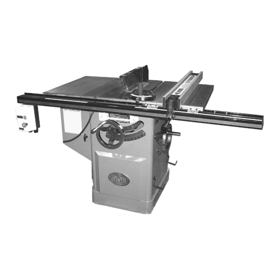
Contents of the Shipping Containers Oliver 4015, 10” Professional Tablesaw Once the top is removed the saw will be as shown with the left extension wing already attached. Inspect for freight damage and call the freight carrier if any. Contents Blade guard 2. -
Page 7: Machine Preparation And Setup
Machine Preparation and Setup WARNING! The equipment used to lift this machine must have a rated capacity at, or above the weight of the tablesaw. Failure to comply may cause serious injury! The tablesaw must be positioned on a smooth, level surface. -
Page 8: Rail Assembly
Rail Assembly 1. Rest the front guide support bracket on the switch box as shown in Figure 4 and secure into place using the chamfered bolts, nuts and washers provided in hardware packet 7. Note that the two outside holes require a nut and washer as well as a bolt while the four inside holes require the bolts only. -
Page 9: Fence Assembly And Adjustment
Fence Assembly and Adjustment 1. Place the fence on the guides as shown in Figure 7. Look for the rubber nib on the underside of the fence as shown and make sure it lines up with the back support rail. 2. -
Page 10: Adjusting The Scale Reader
Adjusting 45° and 90° Stops The stops have been adjusted at the factory and should not need any adjustment. If you need to adjust the stops: 90° Stop 1. Disconnect saw from power source. 2. Raise the saw blade to its maximum height by turning the blade raising handwheel clockwise as far as it will go. -
Page 11: Leveling Table Insert
45° Stop Loosen the 45° stop (C, Figure 14) and then tilt the blade until it mates up with the guage as shown in Figure 14. Make sure the guage is between the saw teeth. Tighten the 45° stop. Push and hold the 45° set button as shown in Figure 15 until the display stops blinking. -
Page 12: Splitter And Blade Guard Assembly
Splitter and Blade Guard Assembly 1. Disconnect saw from power source. 2. Remove table insert by loosening the screw at the front of insert. Pull up and towards you to release the rear clip. 3. Insert the blade guard shaft (D, Figure 17) into rear trunion through opening at rear of saw. - Page 13 Splitter and Blade Guard Assembly (cont.) 9. Place a straight edge against the splitter and blade to make sure they align, as shown in Figure 20. If adjustment is necessary use the provided wrench to loosen the jam nut (E, Figure 21) on the rear fork.
-
Page 14: Miter Gauge
Miter Gauge 1. Slide the miter gauge bar into the miter gauge slot in table. Loosen the handle (A, Figure 23) and pull out indexing rod (B, Figure 23) to pivot the miter gauge body. 2. Push the indexing rod in to engage the preset stops (C, Figure 23). -
Page 15: Electrical Connections
220V. If you need to switch the tablesaw from 220V to 440V have a qualified electrician make the changes. Oliver Machinery recommends using a dedicated circuit. Make sure the voltage of your power supply matches the specifications on the motor plate of the machine. -
Page 16: Replacing And Tensioning The Drive Belt
Replacing and Tensioning V-Belt 1. Disconnect saw from power source. 2. Lower the blade to its lowest position and open the motor cover door. 3. Loosen the hex nut (B, Figure 26). 4. Take tension off of the belt (A, Figure 26) by lifting up on the motor. -
Page 17: Troubleshooting
Troubleshooting Description of Symptoms Possible Cause Corrective Action 1. Fuse blown or circuit breaker 1. Replace fuse or reset circuit tripped breaker 2. Have cord replaced Cord Damaged 3. Replace switch 3. Faulty switch 4. Check connection 4. Not connected to power Machine will not start source 5. - Page 18 1. Reposition on flat, level 1. Stand on uneven floor surface 2. Damaged saw blade 2. Replace saw blade 3. Bad V-belts 3. Replace V-belts Saw vibrates excessively 4. Bent pulley 4. Replace pulley 5. Improper motor mounting 5. Check and adjust motor 6.
- Page 19 Main 230297-615 Fixing Rope 006001-009 Flat Washer 5.2*10*1.0t 000303-101 Round Head Screw M5*0.8P*6 000203-101 Set Screw M6*1.0P*6 000302-101 Round Head Screw M4*0.7P*6 TH17-01 Motor Ass’y...
- Page 20 012003-007 5*5*20 380383-902 Motor Pulley 014314-000 Belt 180J-9 006001-090 Flat Washer 12.2*22*2.0t 009017-100 Hex Nut 1/2”-13NC 006001-096 Flat Washer 13.5*32*3t 050584-008 Motor Bracket 000004-103 Hex Screw M10*1.5P*30 360284-901 Bolt 380384-902 Blade Pulley 490318-000 Sensor Ass’y 030208-000 Ball Bearing 6204-2NSE 000301-201 Round HD Phil.
- Page 21 011003-104 Spring Pin 5*25 360272-901 Elevating Worm Shaft 130061-000 021801-000 Retaining Ring NB-1722 171749-901 Bushing 006006-106 Flat Washer 19.1*25.4*1.6 003202-107 Set Screw 5/16”-18NC*5/16” 360376-901 Fixed Ring 000203-105 Set Screw M6*1.0P*14 240049-000 Hand Wheel 920662-000 Lock Bolt Ass’y 360036-000 Lock Bolt 250433-615 Lock Handle 230114-906...
- Page 22 4015 Part # Description Specifi cation Quantity Acc. 921152-000 Fence Ass’y 000304-202 Round HD Phil. Screw M6*1.0P*10 006002-023 Flat Washer 6.3*13*2.0t 250470-620 Indicator 250472-621 Plastic Set Screw M12*1.75P 000004-306 Hex Screw M10*1.5P*50 250505-615 Rear Fence Friction Pulley 000103-108 CAP Screw M6*1.0P*25...
- Page 23 006001-054 Flat Washer 8.5*20*2t 008015-100 Hex Nut M8*1.25P(12B*6.5H) 921153-000 Spreader Guard Ass’y 010302-000 Push Nut SPN-6 250180-627 Blade Guard 360442-901 171769-904 Connecting Plate 170522-901 Anti-Kick Pawl 130072-000 Fix Collar 011002-105 Spring Pin 4*20 360681-901 171420-904 Spreader 280061-000 Spring 571157-000 Warning Plate RYOBI 000302-101 Round HD Phil.
- Page 24 Table 000203-102 Set Screw M6*1.0P*8 250551-000 Table Insert 000402-104 Flat Head Screw M5*0.8P*12 000104-108 CAP Screw M8*1.25P*25 171422-422 Rear Rail 006305-100 Spring Washer 8.2*15.4 008006-100 Hex Nut M8*1.25P(13B*6.5H) 050330-000 Extension Table 000003-104 Hex Screw M8*1.25P*20 050581-000 Table 001903-103 Set Screw M8*1.25P*20 001903-106 Set Screw...
- Page 26 Extended Rails with Side Table Descriptions Right Extension Table Ass’y Bagged Hardware Kits Connecting Plate Socket HD Bolt M8*1.25P*25 Phillips Head Screw M6*1.0P*12 Flat Washer 6.6*13*1.0t Flat Washer 8.5*23*2.0t Hex HD Bolt M8*1.25P*12 Hex Nut M6*1.0P(10B*5H) Hex Nut 3/8”-16NC(12.4B*8.33H) Table Leg Ends Bolt Hex HD Bolt M6*1.0P*12 Polybag...
- Page 28 Rear Extension Table Ass’y Bagged Hardware Kits Phillips Head Screw M6*1.0P*12 Flat Washer 6.6*13*1.0t Tap Bolt Hex HD Bolt w/Washer M8*1.25P*16/(13B*6.5H) Hex Nut M8*1.25P(13B*6.5H) Hex HD Bolt M6*1.0P*12 Hex Nut 3/8”-16NC(12.4B*8.33H) Table Leg Ends Bolt Hex Nut M6*1.0P(10B*5H) Polybag 200*133()*0.1t Table Top Board Extension Table Support Rear Extension Table Support Bracket...
Need help?
Do you have a question about the 4015 and is the answer not in the manual?
Questions and answers