Table of Contents
Advertisement
Quick Links
Advertisement
Table of Contents

Related Manuals for Oliver M-5018.002


Summary of Contents for Oliver M-5018.002
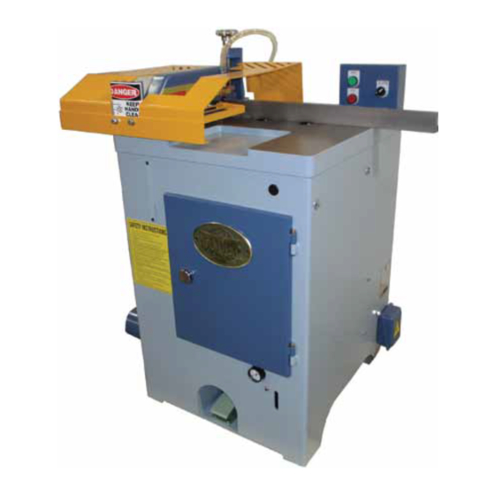
- Page 1 M-5018.002 Cut-Off Saw...
-
Page 3: Table Of Contents
TABLE OF CONTENTS WARNING LABEL LOCATIONS ............01 WARNING LABEL (1 )~(3) ............... 02~04 GENERAL SAFETY RULES FOR WOODWORKING MACHINERY ......05~06 ADDITIONAL SAFETY RULES FOR WOODWORKING MACHINERY ....07 UNPACKING AND CHECKING CONTENTS ......... 08 OPTIONAL EQUIPMENT ..............09 CLEANING THE MACHINE .............. - Page 4 TABLE OF CONTENTS CONNECT DUST COLLECTION SYSTEM ........... 24 MOUTING INFEED AND OUTFEED CONVEYOR TABLE (OPTIONAL)(1)""(3) ....25~27 LEVELING CONVEYOR TABLE TO MACHINE TABLE ....28~29 ADJUSTING WORKING HEIGHT ............30 ADJUSTING BLADE RAISING HEIGHT ..........31 ADJUSTING FENCE SQUARENESS TO SAWBLADE (1 )~(5) ....... 32~36 SAW BLADE (OPTIONAL) ..............
-
Page 5: Warning Label Locations
WARNING LABEL LOCATIONS 1, ll"ad and undcrst�nd i11'1 O, Jl"'r�lion Manual and •II "'1f@lf labels w(Qfl1 opel'llllllfl tl!IS mtlCl'\1111, I"'"'"" 2, On ly a tmlnad i1' 11> I><! p ,lf111illl!d lo orw n!<! 1111< m1<:hkl e , Trainin g $ 1\o�ld IIIClU® IM!n.teUon in o p e tl\l lan unde:r rn:nnmf o:ondffi o t¥•... -
Page 6: Warning Label (1 )~(3)
WARNING LABEL (1) KEEP HANDS CLEAR The warning label "KEEP HANDS CLEAR", shown as above, is attached to the sawblade front guard. It warns the operator to keep hands out of this area. - Page 7 WARNING LABEL (2) The warning label "Rotating blade hazard". Do not operate with guard removed. Lockout/ tagout before servicing", shown as above, is attached to side guard. It warns the operator do not operate the machine when the sawblade guard is opened.
- Page 8 SAFETY INSTRUCTIONS LABEL (3) 1. Read and understand the Operation Manual and all safety labels before operating this machine. 2. Only a trained person is to be permitted to operate this machine. Training should include instruction in operation under normal conditions and emergency situations. 3.
-
Page 9: General Safety Rules For Woodworking Machinery
GENERAL SAFETY RULES FOR WOODWORKING MACHINERY (1) Know your machine. For your own safety, read the operation manual carefully. Learn its applications and limitations, as well as specific potential hazards pertinent to this machine. Make sure the machine is properly grounded. Keep guards in place and in working order. - Page 10 GENERAL SAFETY RULES FOR WOODWORKING MACHINERY (2) 15. Maintain machine in top conditions. Keep machine clean for best and safest performance. Follow instructions or lubricating and changing accessories. 16. Disconnect machine form power source. Before servicing and when changing accessories, or when mounting and remounting motor. 17.
-
Page 11: Additional Safety Rules For Woodworking Machinery
ADDITIONAL SAFETY RULES FOR WOODWORKING MACHINERY 1. Read and understand the operation manual before operation. 2. Keep hands away the cutting area. 3. Always disconnect the power source before making any adjustments. 4. Do not operate the machine in case air pressure does not reach the normal working pressure. -
Page 12: Unpacking And Checking Contents
UNPACKING AND CHECKING CONTENTS The cut-off saw is shipped complete in one wooden crate in addition to infeed and outfeed conveyor tables. Carefully unpack the machine and ensure that all parts are present and free of damaged. If any parts are missing or damaged, contact your local dealer immediately. -
Page 13: Optional Equipment
OPTIONAL EQUIPMENT • Sawblade • lnfeed and outfeed roller conveyor, length as required. • Safety guard. -
Page 14: Cleaning The Machine
CLEANING THE MACHINE After the machine is unpacked, remove the rust preventative oil that coats the machine with a cloth soaked in kerosene. Do not use gasoline or lacquer thinner, as this can damage the painted parts of the machine. -
Page 15: Machine Specifications
MACHINE SPECIFICATIONS S PECIFICATIONS 18" CUT-OFF SAW ITEM Cutting capacity (thickness x width) 2" 12", 3" 11", 4" 10" Cycle speed 45 strokes/min Cycle operation Saw blade size ( optional) 18" Saw arbor diameter 1" Saw blade speed 3600 RPM Dust exhaust diameter 0 4"... -
Page 16: Cutting Capacity Diagram
CUTTING CAPACITY DIAGRAM HOLDDOWN [LAMP ----..__ SAwBlADE --..5" � ..� 4" "- ::i 3 " " ..2 2 " � � � r· � 10'' 11" 12" 1 3 ' ' 5· · g· · 3' ' WOOD THICKNESS(1 nch) -
Page 17: Legend Of Cut-Off Saw
LEGEND OF CUT-OF! F SAW ..:to. 9"�· ·. ��' 1. Infeed COrw'e)'Of {O ptioMi} Foot Pedall 6. Hold-down damp 2. CQntn::>I pane, l 7. Sawblade(opti�) 12. C,anbine-t 3. fein<e 8. Outf ttd conveyor (optkmal) 13. Junction box· 4. Emergency stop switch 9, Dust. -
Page 18: Electric Control Switches
ELECTRIC CONTROL SWITCHS 1. SAWBLADE START SWITCH: Press this switch for starting the sawblade running. 2. SAWBLADE STOP SWITCH: Press this switch for stopping the sawblade. 3. AIR POWER SWITCH: Turn this switch to ON position, and then air enters into the air circuit. Turn this switch to OFF position for shutting off air pressure. -
Page 19: Emergency Stop Switch
EMERGENCY STOP SWITCH This is an emergency stop switch for air system. When this switch is pressed, the clamp raises immediately to release the workpiece. - - EMERGENCY STOP SWITCH & . CAUTION This emergency stop switch only shut off air power. -
Page 20: Foot Switch (1 )(2)
FOOT SWITCH (1) The machine operation is controlled by a foot switch. When operator treadles on the foot switch one time then release it, motion sequences are performed as below: The clamp comes down to hold the workpiece. 2. The sawblade rises up to cut off the workpiece. 3. - Page 21 FOOT SWITCH (2) When the operator keeps on pressing the foot switch about over 1 minute, motion sequences are performed as below: 1. The clamp come down to bold the workpiece. 2. The sawblade rises up to cut off the workpiece. 3.
-
Page 22: Installing Machine
INSTALLING MACHINE The cut-off saw does not need to be bolted into the concrete floor, however a solid and plan enough concrete floor is requested. Leave proper space around the machine for conveniently handling the material to be cut. Make leveling adjustment after the machine has been located at the work site. -
Page 23: Adjust Machine Leveling
ADJUST MACHINE LEVELING To perform the machine leveling adjustment, place a precision level gauge on the table. Turn the leveling screw by using an open and wrench, located under the 4 corners of the cabinet. LEVELING SCREW (INSIDE OF THE CABINET) -
Page 24: Connect Power Wires (1 )(2)
CONNECT POWER WIRES (1) This machine has been factory test by using the proper voltage before shipment. Before the machine is connected with the factory power, be sure the power supply is the proper voltage, hertz and phase as the machine prewired. - Page 25 CONNECT POWER WIRES (2) If the saw blade runs to the direction as the arrow sign instructed, then the power wires are correctly connected, otherwise you should change any two of the three power wires to obtain a correct running direction of the sawblade.
-
Page 26: Air Circuit Connection
AIR CIRCUIT CONNECTION The quick air connector is provided on the Filter/Regulator/ Lubricator unit; simply connect the air source to the air connector. The Filter/Regulator/Lubricator unit (F.R.L. UNIT) is mounted at the front right side in the cabinet. Open the right side door you can find it. The working pressure is indicated on pressure gauge of F.R. -
Page 27: Filter/Regulator/Lubricator Unit
FILTER/REGULATOR/LUBRICATOR UNIT 1. PRESSURE GAUGE The pressure for the air system is shown on this pressure gauge. Working air pressure can be adjusted by turning the pressure regulator located on the filter bowl. Turn it clock-wisely for increasing pressure. Turn counter clock-wisely for decreasing pressure. -
Page 28: Connect Dust Collection System
CONNECT DUST COLLECTION SYSTEM The cut off saw is equipped with a dust exhaust outlet, located at the left side of the machine. The dust exhaust outlet diameter is 04". Use a proper diameter of flexible hose to connect the exhaust outlet to a dust collector. DUST EXHAUST OUTLET(04") -
Page 29: Mouting Infeed And Outfeed Conveyor Table (Optional)(1)""(3)
MOUNTING INFEED AND OUTFEED CONVEYOR TABLE (OPTIONAL) (1) 1. The instructions below are for mounting the infeed and outfeed conveyor table. Mounting procedures for infeed and outfeed conveyor table are the same. 2. When mounting the infeed and outfeed conveyor, ask another one to help you for moving the conveyor table. - Page 30 MOUNTING INFEED AND OUTFEED CONVEYOR TABLE (OPTIONAL) (2) Place the infeed conveyor table on the support plate. Align the two holes on the end of the infeed conveyor table with the two horizontal slots on the support plate. And slightly tighten the infeed conveyor table. CONVEYOR TABLE SUPPORT PLATE After the infeed conveyor table has been mounted, be sure to make...
- Page 31 MOUNTING INFEED AND OUTFEED CONVEYOR TABLE (OPTIONAL) (3) Place a straight edge on the table surface across the conveyor roller; raise the conveyor table until the roller just touches the straight edge. Then tighten the lock screws. CONVEYOR TABLE CONVEYOR TABLE SUPPORT PLATE SUPPORT PLATE SUPPORT PL ATE...
-
Page 32: Leveling Conveyor Table To Machine Table
LEVELING CONVEYOR TABLE TO MACHINE TABLE (1) Leveling adjustment for the infeed and outfeed conveyor table are the same. Place a straight edge across the machine table and infeed conveyor roller. 3. Raise the infeed conveyor table until the conveyor roller just touches the straight edge. - Page 33 LEVELING CONVEYOR TABLE TO MACHINE TABLE (2) 4. Tighten the two screws securely that fasten the infeed conveyor table to the cut-off saw. LOCK SCREW 5. Repeat above procedures to level the outfeed conveyor table.
-
Page 34: Adjusting Working Height
ADJUSTING WORKING HEIGHT 1. Raise the hold-down clamp by pushing in the AIR ON/OFF control collar on the quick air connector. Place a workpiece to be cut under the hold down clamp. 3. Turn the height adjustment knob to raise or lower the hold down clamp. If you feel heavy to turn this knob, pull back the AIR ON/OFF CONTROL COLLAR (air off) for effortless turning of the knob. -
Page 35: Adjusting Blade Raising Height
ADJUSTING BLADE RAISING HEIGHT The sawblade raising height is controlled by a limit switch built in the machine cabinet. When the blade is raising and its bracket touches the limit switch, then the sawblade will lower to its original position. The two knobs, located at the left front side of machine cabinet, are used to adjust the limit switch position. -
Page 36: Adjusting Fence Squareness To Sawblade (1 )~(5)
ADJUSTING FENCE SQUARENESS TO SAWBLADE (1) Disconnect the machine from the power source. Raise the hold-down clamp by pushing in the AIR ON/OFF control collar on the quick air connector. PRESSURE ADJUST KNOB QUICK AIR CONNECTOR AIR ON/OFF CONTROL COLLAR PRESSURE GAUGE LLBACK◄... - Page 37 ADJUSTING FENCE SQUARENESS TO SAWBLADE (2) Fix the hold down clamp by placing a wood block under it. Note the wood block position should not interfere with the sawblade raising path. WOOD BLOCK...
- Page 38 ADJUSTING FENCE SQUARENESS TO SAWBLADE (3) Turn air power switch to on position on the control panel. Treadle on the foot switch to raise the sawblade. When your foot releases the foot switch, the sawblade will lower. At this time you can turn air power switch to off position to fix the sawblade at the raising position.
- Page 39 ADJUSTING FENCE SQUARENESS TO SAWBLADE (4) Check squareness between the fence and the sawblade by using a combination square. Keep the combination square against the flat part of the blade. Do not have the combination square touch the blade teeth. COMBINATION FENCE SQUARE...
- Page 40 ADJUSTING FENCE SQUARENESS TO SAWBLADE (5) 7. If the fence is not square to the sawblade, loosen the two lock screws that tighten the fence. 8. Move the fence until it is correctly square to the sawblade. Then tighten the two lock screws securely.
-
Page 41: Saw Blade (Optional)
SAW BLADE (OPTIONAL) NOTE: This cut-off saw accommodates an 18" diameter sawblade. The suitable sawblade is a 18" diameter carbide tipped blade. Teeth numbers 120. Blade bore size is 1" diameter. Use only sawblade for maximum safe operating speeds of 3600 RPM or greater. -
Page 42: Replacing The Sawblade
REPLACING THE SAWBLADE (1) & WARNING Disconnect the machine from power source before replacing the saw blade. Disconnect the machine from the power source. Open the left side door. Use the supplied door handle to turn the door latch for opening the door. Loosen the sawblade lock screw by using the supplied "T"... - Page 43 REPLACING THE SAWBLADE (2) Remove sawblade lock screw and flange. Take out the old sawblade. SAWBLADE FLANGE Fit a sawblade onto the arbor. Ensure that the arbor and flange are clean of dust and debris before fitting the saw blade. Be sure the saw blade teeth point toward its running direction.
-
Page 44: Adjusting V-Belt Tension
ADJUSTING V-BEL T TENSION After the machine has been operated for a long period, the V-belt tension may loosen gradually. At this time you need to adjust the V-belt tension. Inadequate tension in the V-belt will cause the belt to slip from the pulley. To adjust V-belt tension: Disconnect the machine from the power source. - Page 45 ADJUSTING V-BEL T TENSION Open the front door by using the supplied door handle. Move the motor forward to increase the belt tension. After V-belt tension is adjusted tighten the 4 lock screws on the table.
-
Page 46: Replcing V-Bel T
REPLCING V-BEL T If the saw arbor s p eed decreases or an abnormal sound when startin g the sawblade , then it is su gg ested to re p lace the V-belt. V\/hen re p lacin g the V-belt , re p lace the com p lete three belts to ensure a consistent tension on each belt. -
Page 47: Identification Before Operation
IDENTIFICATION BEFORE OPERATION 1. Make sure all function of switches is normal. 2. Make sure the sawblade running direction is correct. 3. Remove all adjustment tools or any other object from the machine. 4. Check to see if air pressure is proper or not. 5. -
Page 48: Operation Procedures
OPERATION PROCEDURES 1. Properly adjust the hold-down clamp according to the workpiece thickness. 2. To adjust hold-down clamp position, place a workpiece to be cut under the hold-down clamp, and adjust the hold-down clamp position by turning the adjustment knob. Normally the hold-down clamp position is adjusted to s"... -
Page 49: Lubrication
LUBRICATION 1. The saw arbor bearings are sealed and need no lubrication. 2. Lubricate the saw head bracket pivot with oil. 3. Periodically check the oil amount in lubricator bowl on F.R.L. combination unit. -
Page 50: Maintenance
MAINTENANCE Buildup of saw dust and other debris can cause the machine to cut inaccurately. Periodic cleaning is not only recommended, but mandatory for accurate-cutting. Periodically check the oil in the lubrication cup of the filter/ regulator/lubricator combination unit. Periodically check the water accumulated in the filter cup of the filter/regulator/lubricator combination unit. -
Page 51: Trouble Shooting
TROUBLE SHOOTING TROUBLE SHOOTING TROUBLE PROBABLE CAUSES CORRECTION 1 . Factory power abnormal 1. Check SAWBLADE STARTING 2. Power wire damaged 2. Replace FAILED 3. Overload thermal pin kick out 3. Press it down POOR 1. Sawblade dulled 1. Sharpen sawblade CUTTING 2. -
Page 52: Electric Wiring Diagram
18" CUT-OFF 3 8 , . _ , , , , _ 3 6 \ � , � 39"' ' � 1!' · • · · 1 · · , : � �- - � .._ 2 , 4 2 <... -
Page 53: Air Circuit Diagram
PART LIST 18" CUT-OFF SAW DESCRIPTION Q'TY DESCRIPTION Q'TY Cabinet Cushion Emergency stop Connecting Link Dust Port Air Cylinder Side Door Pressure Regulating Valve Door Lock Toggle Coupling Pin 1 /2" x2" Lock Handle Front Door T-clamp Pedal Gasket Magnetic Switch Socket Wrench 19mm Wire Connecting Plate Electrical Box... -
Page 54: Parts List
PARTS LIST 18" CUT-OFF SAW... - Page 55 PART LIST 18" CUT-OFF SAW DESCRIPTION Q'TY DESCRIPTION Q'TY Danger Label Tapper Flange Safety Appurtenance Drive Pulley Lobe Knob Lower Bracket Lock Nut Lower Damper Rubber Ring Limit Switch Bracket Adjustable Seat Limit Switch Guide Screw Switch Box Button Stop Button Air Inlet Switch Fence Table...
- Page 56 ELE T IC (") 'S-l ,r-1 □...
- Page 57 Air Valve Logical valve Air T-Fitting Air T-Fitting Safety Switch Air Filter··Pressure Regulator-Oil Feeder Air Switch(on/off) "" ;" '"' � Foot Switch "' "' ::;· "' "'I .."' ::,:, � :::, '"' $" ::;. s· < "" I»...
Need help?
Do you have a question about the M-5018.002 and is the answer not in the manual?
Questions and answers