
Related Manuals for Oliver 5015


Summary of Contents for Oliver 5015
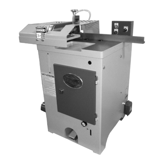
- Page 1 5015 14” Cut Off Saw Owner’s Manual Oliver Machinery M-5015 5/2014 Copyright 2003-2015 Seattle, WA info@olivermachinery.net www.olivermachinery.net...
-
Page 2: Table Of Contents
TABLE OF CONTENTS I. GENERAL DESCRIPTIONS ..............01 II. SPECIFICATIONS.................. 02 III. CUTTING CAPACITY DIAGRAM ............02 IV. CAUTIONS BEFORE OPERATING ............03 V. OPERATING PROCEDURES ..............04 VI. MAINTENANCE & SETVICE ..............04 VII. REMARKS ..................... 05 VIII. ADDITIONAL SAFETY RULES FOR THIS MACHINE (1) (2) .... 06-07 IX. -
Page 3: General Descriptions
I. GENERAL DESCRIPTIONS Much thanks for our honorable customers whom to select our products, 14” Auto Hi-speed Cut-Off Saw. We deep believe your intelligent selection which will make you feel easy and satisfactory. In order to assist you realize the machinery character and how to operate, maintain the machinery etc., affairs. -
Page 4: Specifications
II. SPECIFICATIONS 14” CUT-OFF SAW Cutting capacity (thickness x width) 1" x 10", 2" x 9", 3" x 8" Cycle speed 95 strokes/min Cycle operation Saw blade size (optional) 14" Saw arbor diameter 1" Saw blade speed 4100 RPM Dust exhaust diameter Ø4"... -
Page 5: Cautions Before Operating
IV. CAUTIONS BEFORE OPERATING 1. After the machine is transported to the installed site which must be cared to take off the exporting case and the install site must be flatten and rugged. If there are not flatten which can be inserted the shim at the bottom of the machine, so that there are not swung. -
Page 6: Operating Procedures
V. OPERATING PROCEDURES: 1. Adjust the angle between guide fence and circular saw which s corresponded to the being cutting angle. 2. Turn selecting switch of air inlet to the ON position. 3. Start the electric power on. 4. Pedaling on the foot pedal switch and then, the cutting process can be processed. -
Page 7: Remarks
VII. REMARKS 1. When operating, if the workpiece is clogged or any portion of the machine must be adjusted, beware: turn off the electric power and then handle again. 2. During operating, the operator must be far from the range of circular saw processing which can avoid the breakage fly out. -
Page 8: Additional Safety Rules For This Machine (1) (2)
VIII. ADDITIONAL SAFETY RULES FOR THIS MACHINE (1) 1. As with all machine, there is a certain amount of hazard involved with the use of this machine. Use the machine with the respect and caution demanded where safety precautions are concerned. When normal safety precautions are overlooked or ignored, personal injury to the operator can result. - Page 9 VIII. ADDITIONAL SAFETY RULES FOR THIS MACHINE (2) 8. NEVER LEAVE TOOL RUNNING UNATTENDED. TURN POWER OFF. DO NOT leave tool until it comes to a complete stop. 9. MAKE SURE wiring codes and recommended electrical connection instructions are followed, and that the machine is properly grounded. 10.
-
Page 10: Replacing The Sawblade (1)(2)
IX. REPLACING THE SAWBLADE (1) 1. Disconnect the machine from the power source. 2. Open the left side door. Use the supplied door handle to turn the door latch for opening the door. 3. Loosen the sawblade lock screw by using the supplied "T" wrench. - Page 11 IX. REPLACING THE SAWBLADE (2) 4. Remove sawblade lock screw and flange. Take out the old sawblade. SAWBLADE FLANGE 5. Fit a sawblade onto the arbor. Ensure that the arbor and flange are clean of dust and debris before fitting the saw blade. 6.
-
Page 12: Adjusting V-Belt Tension (1)(2)
X. ADJUSTING V-BELT TENSION (1) After the machine has been operated for a long period, the V-belt tension may loosen gradually. At this time you need to adjust the V-belt tension. Inadequate tension in the V-belt will cause the belt to slip from the pulley. - Page 13 X. ADJUSTING V-BELT TENSION (2) 3. Open the front door by using the supplied door handle. 4. Move the motor forward to increase the belt tension. MOTOR V-BELT 5. After V-belt tension is adjusted tighten the 4 lock screws on the table.
-
Page 14: Diagrams And Part Lists
DIAGRAMS AND PART LISTS 14〞 〞 〞 〞 CUT-OFF SAW... - Page 16 PART LIST 14” CUT-OFF SAW DESCRIPTION Q’TY DESCRIPTION Q’TY Cabinet Limit Switch Stop Emergency stop S.W. Limit Switch Lobe knob with 3/8” threaded stud Metal Pad Side Door Stud Bolt Door Lock Support Frame Lock Handle Split Pin Dust Port Coupling Pin Front Door Support Angle Steel...
- Page 18 PART LIST 14” CUT-OFF SAW DESCRIPTION Q’TY DESCRIPTION Q’TY T-clamp C-Ring Gasket Bearing 6205zz Socket Wrench 19mm Bracket Danger Label Shaft Safety Appurtenance Suspension Bran Lobe Knob Flange Washer Lock Nut Saw Blade Rubber Ring Inside Flange Adjustable Seat Locknut Guide Screw Bearing 6206zz Switch Box...
Need help?
Do you have a question about the 5015 and is the answer not in the manual?
Questions and answers