
Related Manuals for Oliver 4680


Summary of Contents for Oliver 4680
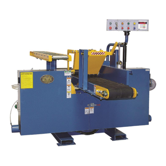
- Page 1 4680 Band Resaw Owner’s Manual Oliver Machinery M-4680 10/2013 Copyright 2013 Seattle, WA info@olivermachinery.net www.olivermachinery.net...
- Page 2 Oliver makes every effort possible to assure that its equipment meets the highest possible standards of quality and durability. All products sold by Oliver are warranted to the original customer to be free from defects for a period of 2 (two) years on all parts, excluding electronics and motors, which are warranted for 1 year.
-
Page 3: Table Of Contents
SECTION 1:SPECIFICATION SECTION 2:SAFETY SECTION 3:CIRCUIT REQUIREMENTS SECTION 4:GENERAL INFORMATION 11~12 SECTION 5:MACHINE FEATURES 13~15 SECTION 6:INSTALLATION 16~17 SECTION 7:CONTROL PANEL SYSTEM 18~24 SECTION 8:ADJUSTMENT INSTRUCTION 24~29 SECTION 9:MAINTENANCE 30~31 SECTION 10:OPTIONAL-MIST COOLANT SYSTEM... -
Page 4: Section 1:Specification
SECTION 1:SPECIFICATIONS ---------------------------------------------------------------------------------- Model SINGLE HEAD BAND SAW 300mm(W) x 250mm(H)(12"x10") Max. Workpiece Size Conveyor Belt Size 285mm(W) x 5470mm(L) 28" Saw Wheel Diameter 1" Saw Wheel Width 168"( L )x1"( W ) Saw Blade Size 4"x4 Dust Hood Diameter Main Specifications:Digital Readout Type CH-525 In-feed Speed... -
Page 5: Section 2:Safety 5~8
SECTION 2:SAFETY ---------------------------------------------------------------------------------- WARNING: For Your Own Safety, Read Instruction Manual before Operating this Equipment The purpose of safety symbols is to attract your attention to possible hazardous conditions. This manual uses a series of symbols and signal words which are intended to convey the level of importance of the safety messages. - Page 6 nameplate. An undersized cord will cause a drop in line voltage resulting in loss of power and overheating. Your extension cord must also contain a ground wire and plug pin. Always repair or replace extension cords if they become damaged. Minimum gauge for extension cords LENGTH AMP RATING...
-
Page 7: Section 2:Safety
you give in regards to the operation of the machine are approved, correct, safe, and clearly understood. WARNING: Additional Safety Instructions for Bandsaw 1. Do not operate with dull or badly worn blades. Dull blades require more demand on the motor and are less likely to cut precisely. -
Page 8: Additional Safety Instructions For Hydraulics
WARNING: Additional Safety Instructions for Hydraulics 1. Be familiar with the hazards of hydraulic injection injuries. Leaking hydraulic fluid may have enough pressure to penetrate skin. Never use your hands to check for suspected hydraulic leaks. Hydraulic fluid that is injected into skin is a medical emergency that may cause infection, disability, amputation or death. -
Page 9: Section 3:Circuit Requirements
SECTION 3:CIRCUIT REQUIREMENTS ------------------------------------------------------------------------------------- WARNING: Serious personal injury could occur if you connect your machine to the power source before you have completed the setup process. Do not connect the machine to the power source until instructed to do so. The Model is wir for 3-phase operation. -
Page 10: Section 5:Machine Features 11~12
SECTION 5:MACHINE FEATURES ------------------------------------------------------------------------------------- Main Features A. Control Panel – Digital Readout B. Shock Absorber For front pressure roller go down. C. Air Cylinder For front pressure roller go down. D. 4" Dust Port Allows the resaw to be connected to a dust collection system. - Page 11 E. Control Panel Controls power to the main motor and the hydraulic motor. F. Front Pressure Rollers Maintain downward pressure on the board to keep it steady during cutting. G. Back Pressure Rollers Maintain downward pressure on the board to keep it steady during cutting. H.
-
Page 12: Section 6:Installation
SECTION 6:INSTALLATION ------------------------------------------------------------------------------------ Mounting resaw to the floor We recommend that you bolt your new resaw to the floor. Because this is optional and floor materials may vary, floor mounting hardware is not included. It may be necessary to level the floor before installing this machine. - Page 13 Mounting the conveyor belt To install the conveyor belt onto the re-saw: 1. Remove the lag bolts that secure the conveyor belt assembly to the crate pallet. 2. Remove the blade guide from the wheel housing. 3. Lift the conveyor belt onto the resaw body as shown in the right. 4.
- Page 14 Check power wire connection After the power source wires have been connected, check if the power wires are connected to the correct points or not. This can be identified by checking the running direction of the conveyor. If the conveyor belt runs to the connect direction, this means the power wires are connected to the correct points.
-
Page 15: Section 7:Control Panel System
SECTION 7:CONTROL PANEL SYSTEM ------------------------------------------------------------------------------------ Safety rules for control system Do not alter or bypass any protective interlocking systems. All electrical/electronic trouble shooting and repairs should be undertaken only by personnel who are properly trained and skilled. Do not alter the electrical circuits unless authorized to do so by the machine manufacturer. Be fore starting the machine, read and observe all warning labels and markings such as the name plates and indication plated. - Page 16 Switch function control panel A. POWER ON Before pressing this power switch, remember to turn on the master power switch located at left side of the control box. When this switch is pressed and it’s indication lamp lights on, it means the machine is underpowered. B.
-
Page 17: Section 8 : Adjustment Instruction
SECTION 8 : ADJUSTMENT INSTRUCTION ------------------------------------------------------------------------------------- Adjust conveyor table To adjust the conveyor table left to right: 1. Disconnect the resaw from the power source! 2. Use your test board to determine which direction the conveyor table needs to be moved. For example, if the right side of the board was thicker than the left side —you will need to move either the right side of the conveyor up or move the left side of the conveyor down. - Page 18 8. The adjusting nut shown in raises, or lowers, the non-drive side of the bandsaw blade (the side opposite the motor). Insert the pry tool into the adjusting nut. —Rotate the adjusting nut to the right to raise the bandsaw blade. —Rotate the adjusting nut to the left to lower the bandsaw blade.
- Page 19 Adjust conveyor belt 1. Lossen the two roller bracket cap screws on the both side of the conveyor about 3/4 of a turn. 2. Loosen the rear adjustment nuts on both side of the conveyor. 3. Start conveyor belt. 4. Adjust the roller bracket that the belt is hitting by turning the front adjustment nut counter-clockwide half of a turn, and watch the belt tracking.
- Page 20 NOTICE: These instruction are for rough tensioning only. The only way to accurately tension the blade is with a blade tension. Premature blade breakage is often caused by improper blade tensioning. Replacing conveyor To replace the conveyor belts: 1. Start the conveyor belt and stop it when the conveyor belt seam is accessible. 2.
- Page 21 Adjust saw wheel for leveling All the saw wheel have been adjusted properly before shipment, please do not do any adjustment until you change the saw wheel! There are two adjusting screws. To adjust the screws will make the saw wheel surface slide. The purpose is to fix the position of ○...
- Page 22 Saw blade guide adjustment To align the guide blocks: 1. Rotate the wheels by hand and watch how the blade feeds through the blade guides. If the blade feeds through the blade guide without touching the guide block or rotating the support wheel, no adjustment is necessary.
-
Page 23: Section 9:Maintenance
2. Rotate the adjustment shaft until the support wheel is approximately 0.016" behind the back of the blade. Check with a feeler gauge or four thicknesses of a dollar bill. 3. Tighten the lock bolt. 4. Spin the wheels clockwise by hand. If the support wheels turn, increase the spacing between the blade and the bearing (the bearings should only turn when cutting). - Page 24 Note—This page was designed to be copied and used as a check-off chart to help maintain a regular lubrication schedule. □ Check white boxes after lubricating fittings. Date Started: 4680 GREASE SCHEDULE/CHECK-OFF CHART HOURS OF USE MACHINE AREA FITTINGS Main Wheels...
-
Page 25: Hydraulic System Minor Service
Hydraulic reservoir components. Inspect and clean the breather cap and filler screen every 40 hours of regular use. The breather cap is vented to allow the hydraulic system to breathe during operation. Below the breather cap is a plastic filler screen. Visually inspect both the breather cap and the plastic filler screen. -
Page 26: Hydraulic System Major Service
6. Separate the filter from the filter housing by pulling them apart. Note—If you only removed a bare filter, then the housing is still mounted in the tank. Remove it for cleaning. 7. Remove the O-ring from the shoulder of the filter housing and clean the filter housing in a solvent tank. Note—Do not gets solvent on O-rings or they will be damaged. - Page 27 To drain the hydraulic fluid: 1. Read the hydraulic safety instructions on page 6 before continuing. 2. With your drain pan in place, remove the drain plug. 3. Replace the drain plug after the hydraulic tank is completely drained. To clean the tank screen: 1.
-
Page 28: Maintenance Log
Maintenance Log Date Approximate Hours Of Use Maintenance Performed... -
Page 29: Section 10:Optional-Mist Coolant System
SECTION 10:OPTIONAL – MIST COOLANT SYSTEM -------------------------------------------------------------------------------------... - Page 30 OIL TYPE: ESTOL 1545...
Need help?
Do you have a question about the 4680 and is the answer not in the manual?
Questions and answers