
Related Manuals for Oliver 4060


Summary of Contents for Oliver 4060
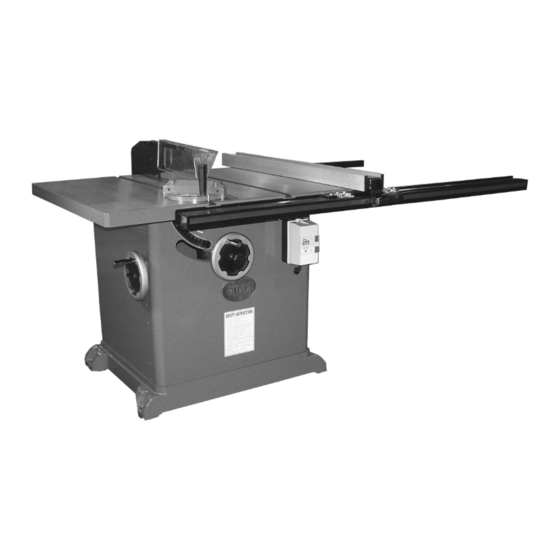
- Page 1 4060 16” Professional Tablesaw Owner’s Manual Oliver Machinery M-4060 09/2008 © Copyright 2003 Seattle, WA info@olivermachinery.net www.olivermachinery.net...
-
Page 2: Warranty
Oliver makes every effort possible to assure that its equipment meets the highest possible standards of quality and durability. All products sold by Oliver are warranted to the original customer to be free from defects for a period of 2 (two) years on all parts, excluding electronics and motors, which are warranted for 1 year. -
Page 3: Warnings
WARNING Read this manual completely and observe all warning labels on the machine. Oliver Machinery has made every attempt to provide a safe, reliable, easy-to-use piece of machinery. Safety, however, is ultimately the responsibility of the individual machine operator. As with any piece of machinery, the operator must exercise caution, patience, and common sense to safely run the machine. -
Page 4: Warnings
Misuse: Do not use this Oliver tablesaw for other than its intended use. If used for other purposes, Oliver disclaims any real or implied warranty and holds itself harmless for any injury or damage which may result from that use. -
Page 5: Table Of Contents
Dust Collection............................12 Electrical Connections..........................13 Replacing the Blade...........................13 Maintenance..............................14 Troubleshooting............................15-16 Specifications Model Number............................4060 Blade Diameter (In)...........................16” Arbor Diameter (In)............................1" Maximum Depth of Cut at 90 Degrees (In)...................5-1/2" Maximum Depth of Cut at 45 Degrees (In)...................4-1/4" Maximum Cut to the Right of Blade......................52”... -
Page 6: Contents Of The Shipping Containers
Contents of the Shipping Containers Oliver 4060, 16” Professional Tablesaw Once the top is removed the saw will be as shown. Inspect for freight damage and call the freight carrier if any. Contents Speed handles 2. Angle height lock 3. Hardware packet (wings) 4. -
Page 7: Machine Preparation And Setup
Machine Preparation and Setup WARNING! The equipment used to lift this machine must have a rated capacity at, or above the weight of the tablesaw. Failure to comply may cause serious injury! The tablesaw must be positioned on a smooth, level surface. -
Page 8: Rail Assembly
Rail Assembly 1. Install the front rail support to the saw using the four supplied chamfered bolts found in the hardware packet of the rails. It is easiest to start with the first hole as shown in figure 4, using the floor to rest the end of the rail on. -
Page 9: Fence Assembly And Adjustment
Fence Assembly and Adjustment 1. Place the fence on the rails and check for alignment with the mitre guage slot as shown in Figure 7. 2. If the fence is not parallel to the mitre guage slot, lift the fence off the guides and place it on the table as shown in figure 8. -
Page 10: Adjusting 45° And 90° Stops
Adjusting 45° and 90° Stops The stops have been adjusted at the factory and should not need any adjustment. If you need to adjust the stops: 90° Stop 1. Disconnect saw from power source. Raise the saw blade to its maximum height by turning the blade raising handwheel clockwise as far as it will go. -
Page 11: Splitter And Blade Guard Assembly
Splitter and Blade Guard Assembly 1. Disconnect saw from power source. 2. Insert the blade guard support rod into hole A as shown in figure 17. Figure 17 3. Remove the table insert then secure the blade guard support rod with lock washer (1) and nut (2) as shown in figure 18. -
Page 12: Miter Gauge
Miter Gauge 1. The miter guage comes pre-assembled. Unpack miter guage clean thoroughly. 2. Be certain the miter guage ‘T’ slots in the table are also thoroughly cleaned. Figure 23 3. The miter guage is guided through the ‘T’ slot with a roller guide at the front of the guide bar. -
Page 13: Electrical Connections
This saw is 3-Phase, 220V/440V pre-wired 220V. If you need to switch the tablesaw from 220V to 440V have a qualified electrician make the changes. Oliver Machinery recommends using a dedicated circuit. Figure 26 Make sure the voltage of your power supply matches the specifications on the motor plate of the machine. -
Page 14: Maintenance
Maintenance WARNING! Disconnect the machine from power source before proceeding with any maintenance, or troubleshooting! Failure to comply may cause serious injury! Periodically clean the inside of the machine for dust control. Use an air hose to blow out dust from motor fan and motor cover. -
Page 15: Troubleshooting
Troubleshooting Description of Symptoms Possible Cause Corrective Action 1. Fuse blown or circuit breaker 1. Replace fuse or reset circuit tripped breaker 2. Cord Damaged 2. Have cord replaced 3. Faulty switch 3. Replace switch 4. Not connected to power 4. - Page 16 1. Reposition on flat, level 1. Stand on uneven floor surface 2. Damaged saw blade 2. Replace saw blade 3. Bad V-belts 3. Replace V-belts Saw vibrates excessively 4. Bent pulley 4. Replace pulley 5. Improper motor mounting 5. Check and adjust motor 6.
- Page 22 4060 Parts List Replacement Parts List for Main Mechanism REF. PART DESCRIPTION QTY. Bushing 3055.00 Bushing 0951.00 Arbor Nut (1" I.D.) 0952.00 Blade Flange (1" I.D.) 0953.00 Arbor Extension (for 1" O.D. blade) 0954.00 Arbor 3008.00 Bearing 3009.00 Socket Head Bolt, 8mm - 1.25 x 25 0957.00...
- Page 23 Round Head Screw, 5mm - 80 x 8 0969.00 Hex Head Bolt, 8mm - 1.25 x 12 0996.00 Wsher, 8mm 0997.00 Front Support Bracket 3024.00 Socket Head Bolt, 8mm - 1.25 x 25 3025.00 Lockwasher, 12mm 1000.00 Hex Nut, 12mm - 1.75 1001.00 Socket Head Bolt, 12mm - 1.75 x 30 3026.00...
- Page 24 Replacement Parts List for Table and Base Assembly REF. PART DESCRIPTION QTY. Extension Table 3040.00 Hex Head Bolt, 12mm - 1.75 x 35 3041.00 Lockwasher, 12mm 1000.00 Blade Insert 3042.00 Setscrew, 6m - 1.0 x 8 1043.00 Table 3043.00 Base 3044.00 Indicator Plate 3045.00...
- Page 25 Replacement Parts List for Rip Fence REF. PART DESCRIPTION QTY. Front Rail 4004.00 Rear Rail 4005.00 Guide Rail 4001.00 Measure Scale 2004.00 Hex Head Screw M8 X 16mm 2219.00 Lock Washer 0978.00 Pan Head Screw M8 x 16mm 2005.00 Fence 4002.00 Fence Bracket Body 4003.00...
Need help?
Do you have a question about the 4060 and is the answer not in the manual?
Questions and answers