WEIGL ProCommander LTC Instruction Manual
Hide thumbs
Also See for ProCommander LTC:
- Instruction manual (87 pages) ,
- Instructions manual (8 pages)
Table of Contents
Advertisement
Quick Links
Advertisement
Table of Contents

Related Manuals for WEIGL ProCommander LTC


Summary of Contents for WEIGL ProCommander LTC
- Page 1 Weigl ProCommander ® Instruction Manual...
- Page 2 Weigl GmbH & Co KG +43 650 84 333 48 www.WeiglControl.com Info@WeiglControl.com Weigl Control (except Americas) Weigl Works, LLC +1 440 941 5849 www.WeiglControls.com Info@WeiglControls.com Weigl Control Americas ProCommander ® Version 1.10 © 2012 – 2019 – Weigl GmbH & Co KG...
-
Page 3: Table Of Contents
Table of Contents 1 Important Information and Safety Tips 7 FCC and CE Compliance ......10 FCC Instruction to User ......10 FCC DECLARATION OF CONFORMITY... 12 CE DECLARATION OF CONFORMITY ..13 2 Warranty ..........15 3 ProCommander LTC pin assignment 17 ®... - Page 4 8 Variable ..........67 9 Control.ini ..........69 Structure of the Control.ini file ....70 9.1.1 !i: Input events ........70 9.1.2 !t: Time events ........ 70 9.1.3 !rc: Real time clock events ....71 9.1.4 !v: Variable events ......73 9.1.5 !d: DMX events ........
- Page 5 12 Programming the ProCommander ® LTC ............97 13 Network connection between ProCommander LTC and Pro I/O ..99 ® 14 Interface protocols ......105 15 Videoplayer Configuration ....107 15.1 Videoplayer Setup ........107 15.1.1 Search for Videoplayer ....107 15.1.2 Videos (Tab) ........
-
Page 7: Important Information And Safety Tips
Weigl covering or relating to any combination, machine or process in which Weigl products or services might be or are used. ATTENTION! - Page 8 ProCommander ® LTC. Failure to do so will void the warranty and Weigl GmbH & Co KG or Weigl Works, LLC will not be liable for any resulting damages. When connecting solenoids, a freewheeling diode for each solenoid is required.
- Page 9 ATTENTION! Damages caused by improper handling, improper wiring or improper use will void warranty and Weigl GmbH & Co KG or Weigl Works, LLC cannot be held liable. ATTENTION! With the removal of the label of a ProCommander ®...
-
Page 10: Fcc And Ce Compliance
Important Information and Safety Tips FCC and CE Compliance Weigl ProCommander LTC have been tested to comply with ® FCC and CE requirements. The ProCommander LTC is low voltage DC devices ® and therefore, neither UL nor CE require safety testing. For... - Page 11 Important Information and Safety Tips • Consult the dealer or an experienced radio/TV technician for help. This equipment has been verified to comply with the limits for a class B computing device, pursuant to FCC Rules. In order to maintain compliance with FCC regulations, shielded cables must be used with this equipment.
-
Page 12: Fcc Declaration Of Conformity
FCC DECLARATION OF CONFORMITY This device complies with Part 15 of the FCC Rules Class B. Application of Council Directives: EMC Directive, 89/336/EEC Manufacturer’s Name: Weigl GmbH & Co KG Manufacturer’s Address: Limberg 3, 4201 Gramastetten, Austria US Importer’s Name: Weigl Works, LLC Importer’s Address:... -
Page 13: Ce Declaration Of Conformity
Weigl ProCommander LTC have been tested to comply with ® CE requirements. Model: Weigl ProCommander ® This product herewith confirmed to comply with the requirements set out in the Council Directive on the approximation of the laws of the Member States relating to Electromagnetic Compatibility Directive 2004/108/EG. - Page 14 This device complies with Part 15 of the FCC Rules Class B. I the undersigned, hereby declare that the equipment specified above conforms to the above directive(s) and standard(s). Place: Gramastetten Date: December 12 , 2012 Full Name: Manfred Weigl...
-
Page 15: Warranty
The customer shall pay all shipping costs to and from Weigl GmbH & Co KG or Weigl Works, LLC should there be a need for parts be repaired or replaced in the ProCommander LTC. The ®... - Page 16 Damage caused by errors in installation. • Damage caused by tampering with the device by persons not expressly authorized by Weigl GmbH & Co KG or Weigl Works, LLC to do so. • Failure to follow the instructions (i.e. connection to the wrong voltage or incorrect input or output circuit).
-
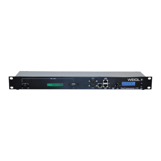
Page 17: Ltc Front
Pin assignment ProCommander LTC 3 ProCommander LTC pin assignment ® ProCommander LTC FRONT ® FRONT WIRING DIAGRAM FOR ProCommander ® Device address 3 (!ssi3#) CAT5 RS232-1/NET-IN RS232-2/NET-OUT Device address 2 (!ssi2#) 1: RS485-2 + 1: RS485-2 + 2: RS485-2 –... - Page 18 The WEM-NET/RS-232 ports are for use of either the proprietary WEM-NET Pro I/O protocol used for the interconnect of various Weigl devices, or the use of external RS-232 input and output devices (adapter required, sold separately). Through the USB port...
- Page 19 Pin assignment ProCommander LTC ATTENTION! Weigl highly recommends to use SLC NAND industrial grade instead of microSD cards. We also offer SLC industrial grade memory cards, which we have tested with our devices. Other cards need to be tested in terms of speed.
- Page 20 Pin assignment ProCommander LTC out by pressing the joystick. Without confirmation, the change is rejected. The menu mode will be automatically exited, when the joystick is not moved for a period of 20 seconds. ATTENTION! Modification in the menu can only be made if no show is running.
-
Page 21: Ltc Rear
Pin assignment ProCommander LTC Starting from LEVEL 3 you will be redirected one LEVEL back or up by moving the joystick to the left. By moving the joystick up and down you can move between the different functions. Enter (the center press of the joystick) confirms your selection. - Page 22 Pin assignment ProCommander LTC ATTENTION! For a higher resolution, please download the wiring diagram from Weigl Support and Solutions Center. POWER The ProCommander LTC can be operated with voltages of ® 12V/ 3A. ATTENTION! The 12V may not be exceeded in any case. Thus, if the power supply has a ripple in the voltage, the peak voltage must not exceed 12V.
- Page 23 Pin assignment ProCommander LTC settings and each respective software manual for additional information. REMOTE 1-8 / 9-16 The ProCommander LTC has 16 remote inputs for connecting ® external dry contacts for the purpose of logic evaluations or show starts. Inputs 9-16 are analog inputs, which can evaluate voltages from 0-14V with a 10-bit resolution.
- Page 24 Conductor). During show programming, this information is routed into the software via the UDP connection used for all other Weigl show communications. This SMPTE "read-in" function can be toggled using the pre-scripted drop down menu commands, as well as the related...
- Page 25 Pin assignment ProCommander LTC The SMPTE timecode can also be used to "jamsync", microSD exported show data during stand-alone playback via the use of ASCII commands such as !rtc1# and !rtc0#. Complete SMPTE operational commands are found pre- scripted in the drop down menu structure of VenueMagic ®...
- Page 26 Pin assignment ProCommander LTC The output is a balanced audio signal, whereby Pin 2,3 are assigned to the left channel and Pin 4,5 to the right channel. Pin 1 is common ground. Supply- and GND-Pins Schematic for output connection: At each Pin 5 of the 6-pole connector block the supply voltage of the power supply is brought out, if the Jumper K 14 is closed.
- Page 27 Pin assignment ProCommander LTC Jumper open Jumper closed...
- Page 28 Pin assignment ProCommander LTC ATTENTION! If the Jumper is closed and the power supply of the ProCommander LTC is used for the operation ® of the connected components, it is important to make sure, that the maximum total current must not exceed 500mA.
-
Page 29: Usb - Driver Installation
USB - driver installation 4 USB – driver installation As soon as the ProCommander LTC is connected to your ® computer, Windows automatically search for the appropriate driver software. When you see this dialog box, select "Browse my computer for driver software". Click on "Browse"... - Page 30 USB - driver installation If you receive the following security warning, confirm with "Install this driver software anyway". Microsoft Windows 8 may require that you turn off during signing in the setup configuration for your computer. Please refer to documentation included with your operating system.
- Page 31 USB - driver installation...
- Page 32 USB - driver installation If you later want to elicit the COM-port, you will find this under "Control Panel" -> "Device Manager" -> "Ports (COM&LPT)".
-
Page 33: Modification Of The Menu Of Procommander ® Ltc
Modification of the menu of ProCommander LTC 5 Modification of the menu of ProCommander ® The functions of the menu are displayed on the display of the ProCommander LTC. This is directly controlled using ® the "Joystick" on the front panel. Therefore, the functions are divided into different LEVELS. -
Page 34: Procommander ® Series
Modification of the menu of ProCommander LTC ProCommander Series ® MENU ProCommander Series – LEVEL 1 & 2 LEVEL 1 LEVEL 2 ProCom Volume All channels will store the same value 0 - 31 Start Show? Menu Main Setup Configure... -
Page 35: Menu
Modification of the menu of ProCommander LTC is running. Therefore you have to move the joystick to the left or right, to decrease or increase volume, now you are on LEVEL 2. As soon as the requested value is displayed, confirm with Enter within 2 seconds. -
Page 36: Mainsetup
Modification of the menu of ProCommander LTC 5.2.1 MainSetup MENU ProCommander LTC – MainSetup – LEVEL 2 Menu LEVEL 3 LEVEL 4 LEVEL 5 MainSetup Set IP-Adrs IP-Adrs 000.000.000.000 Set Port Port 1 – 4 Value 00000 SetFactory Set Factory? - Page 37 Modification of the menu of ProCommander LTC Move the joystick to the right or left to change the requested digit. The underscore below a digit indicates which digit can be changed. You have to move the joystick up or down to adjust a value between 0-9.
- Page 38 Modification of the menu of ProCommander LTC Set Factory With the function "Set Factory" you can restore to factory settings of the ProCommander LTC. Therefore you have to ® activate "Set Factory" by pressing Enter. You will be automatically forwarded to LEVEL 4 of the menu plan.
-
Page 39: Configure
Modification of the menu of ProCommander LTC 5.2.2 Configure MENU ProCommander LTC – Configure – LEVEL 2 Menu LEVEL 3 LEVEL 4 LEVEL 5 Configure LTC-TimeOut Set TimeOut 0 - 250 EaseIn Time Set Ease-In 0 - 250 StrtPlaylst Set StPlyL... - Page 40 Modification of the menu of ProCommander LTC Based on LEVEL 2 you will be forwarded on LEVEL 3 by confirmation with Enter. LEVEL 3 locate under "Configure" following functions: "LTC-TimeOut", "EaseIn Time", "StrtPlaylst", "RS485-2 Drv" and "IgnStartClr". LTC-TimeOut With the function "LTC-TimeOut" you can define the timespan after which the intern time base will be activated, once the external timecode is completed or not sent properly.
- Page 41 Modification of the menu of ProCommander LTC by an abrupt jump within the show, as well as a change from one show to another. Press Enter to activate the menu item "EaseIn Time". In the first line of the display "Set EaseIn:" appears, this corresponds to the LEVEL 4 of the menu plan.
- Page 42 Modification of the menu of ProCommander LTC Move the joystick up or down. If the desired function appears on the display confirm the value by pressing Enter. Once the value is saved, an * asterisk will be displayed. By moving the joystick to the left, you can return to a parent LEVEL.
- Page 43 Modification of the menu of ProCommander LTC corresponds to the LEVEL 4 of the menu plan. The second line of the display shows the current value and corresponds to LEVEL 5 of the menu plan. The * asterisk next to the value indicates that it is currently active.
-
Page 44: Audio
Modification of the menu of ProCommander LTC 5.2.3 Audio MENU ProCommander LTC – Audio – LEVEL 2 Menu LEVEL 3 LEVEL 4 LEVEL 5 Audio Volume Set Volume: 0 - 31 Bass Set Bass: 0 - 15 Treble Set Treble:... - Page 45 Modification of the menu of ProCommander LTC indicates that it is currently active. You can choose between the values of 0 to 31, the value "0" zero corresponds with the minimum and "31" with the maximum volume. You must move the joystick either up or down to set the requested value.
- Page 46 Modification of the menu of ProCommander LTC Treble With the function "Treble" you can change the treble intensity of the left and right channel. For this purpose you have to activate "Treble" with Enter. In the first line of the display "Set Treble:" appears, this corresponds to the LEVEL 4 of the menu plan.
-
Page 47: Realtimeclk
Modification of the menu of ProCommander LTC 5.2.4 RealTimeClk MENU ProCommander LTC – RealTimeClk – LEVEL 2 Menu LEVEL 3 LEVEL 4 LEVEL 5 RealTimeClk Hour Set Hour 0 - 23 Minute Set Minute 0 - 59 Day-Of-Week Set DayOfWk... - Page 48 Modification of the menu of ProCommander LTC Hour With the function "Hour" you can define the hour of the intern real time clock of the ProCommander LTC. You have to ® activate "Hour" by pressing Enter. In the first line of the display "Set Hour:" appears, this corresponds to the LEVEL 4 of the menu plan.
- Page 49 Modification of the menu of ProCommander LTC By moving the joystick to the left, you can return to a parent LEVEL. Minute With the function "Minute" you can define the minute of the intern real time clock of the ProCommander LTC.
- Page 50 Modification of the menu of ProCommander LTC You can choose between the values "Monday (1) – Sunday (7)". You must move the joystick either up or down to set the requested weekday. If the value appears on the display, confirm it by pressing Enter.
- Page 51 Modification of the menu of ProCommander LTC In the first line of the display "Set Month:" appears, this corresponds to the LEVEL 4 of the menu plan. The second line of the display shows the current value and corresponds to LEVEL 5 of the menu plan. The * asterisk next to the value indicates that it is currently active.
-
Page 52: Info
Modification of the menu of ProCommander LTC 5.2.5 Info MENU ProCommander LTC – Info – LEVEL 2 Menu LEVEL 3 LEVEL 4 LEVEL 5 Info Firmware Ver. Firmware Version V0.00 SerialNumber Serial Number 00.00.00.00 MAC-Address MAC-Address 00-00-00-00-00-00 IP-Address IP-Address 000.000.000.000... - Page 53 Modification of the menu of ProCommander LTC IP-Address Here the current IP address of the device will be displayed. Port Here the current values of the ports can be controlled.
- Page 54 Modification of the menu of ProCommander LTC...
-
Page 55: Procommander ® Ltc Configuration
Configuration ProCommander LTC 6 ProCommander LTC configuration ® In addition to the settings of the menu you can program the ProCommander LTC via ASCII commands. This is very useful, ® if you want to change settings via network, USB or commands... - Page 56 Configuration ProCommander LTC exe with double-click. After starting this window appears: Press the button "Scan Devices" and the connected device will be found automatically. By clicking on the listed device, the current settings will be listed. Now you can change the...
- Page 57 Configuration ProCommander LTC subnet mask and save it on the device. With the button "Save Changes" the new parameter are stored permanently in ProCommander LTC. ® If the configuration is made through network you have to be aware, that the...
-
Page 58: Firmware Update
Configuration ProCommander LTC Choose the internet protocol version 4 and press the button "properties". In the following dialog you justify the IP address as 10.0.0.X. The data X has to be unequal 101. The settings for the standard gateway and DNS-server address are not relevant. - Page 59 Configuration ProCommander LTC button "Scan Devices" for the connected ProCommander ® and afterwards click on "Firmware Update" button. In the following dialog choose the new "ProComLTC_Vxxx. hex" file. The data "Vxxx" corresponds to the latest version of the ProComLTC.hex-file. This will be transferred to the ProCommander LTC.
- Page 60 Configuration ProCommander LTC ATTENTION! This operation is ONLY available over network and not via USB or serial connection. Please turn of Wi-Fi and any other connections during the update process to avoid potentially crippling errors to the unit.
- Page 61 Configuration ProCommander LTC ATTENTION! A USB advanced system restore is available using DFU batch files and extended operations through the command line. There is NO USB or serial visual method of updating the firmware at this time. Please see additional information regarding the USB firmware restore process for additional information.
-
Page 62: Firmware Update Via Batch-File
Configuration ProCommander LTC Firmware update via batch-file In the case that you have not installed the driver, follow these steps: • Unzip all files of the ProComLTC_Vxxx.zip file, which you can download from our website, in an empty folder. xxx stands for the latest version of the software. - Page 63 Configuration ProCommander LTC • The device firmware upgrade driver (DFU-driver) is not installed at this moment, if you run the update for the first time. So you will get a DOS-window like this: • If the request for the driver installation is not shown automatically, please power cycle the device.
- Page 64 Configuration ProCommander LTC the number, probably you get an error message, that port cannot be opened, but after a few seconds you should get this window: Once both drivers are installed, all further ProCommander ® updates can be done immediately through the USB interface.
-
Page 65: Dmx-Read In
DMX-Read in 7 DMX-Read in Via the pins 4 and 5 can be read in. As a result, the external DMX-universe can be merged into the internal generated DMX-signal. Furthermore, the integrated map function can be used to control the onboard I/O functions of the ProCommander LTC via the external DMX-signal. - Page 66 DMX-Read in Both values will be compared and the highest value will be transferred into the output-signal. • Merge Change: The value which had been changed as latest will be taken. • Merge Add: Both values will be added and the sum will be transferred into the output-signal.
-
Page 67: Variable
Variable 8 Variable With variables decisions can be made, conditional show starts or counter can be realized. Variables can be manipulated inside a show or through external events. Possible actions are setting a value of a variable or executing mathematical operations like add, subtract, multiply or divide. - Page 68 Variable...
-
Page 69: Control.ini
Control.ini 9 Control.ini The Control.ini file is a new and easy way to assign different input events to any of the available ASCII-commands without any special show programming. It is even possible to assign an input event to several successive commands. An input event may be a change of the remote inputs, a time event or a variable change. -
Page 70: Structure Of The Control.ini File
Control.ini Structure of the Control.ini file It must always start with the definition of a trigger event. As a start condition either an "!i: Input events", "!t: Time events", "!rc: Real time clock events", "!v: Variable events" or "!d: DMX events"... -
Page 71: Rc: Real Time Clock Events
Control.ini also set to "0" zero. Each time value must entered format minutes:seconds. Hours must be converted to minutes. A time of 2 hours, 15 minutes and 20 seconds should be formatted as 135:20. The character after the "t" determines the way the time should be interpreted. - Page 72 Control.ini Every time you power up your device or plug in the card the internal clock will be set to the default values, if you don't insert a battery. And the commands will be executed with a delay. Example: !rc(w=1;d=1;o=1;y=12;h=8;m=10;s=4)!…# w = weekday (value range: 1-7;...
-
Page 73: V: Variable Events
Control.ini !rc(s&10)!…# -> all 10 seconds the downstream command will be executed. !rc(w>2;w<7;h=8)!…# -> from Tuesday till Saturday the downstream command will be executed precisely at 8 a.m. !rc(m&15)!...# -> at every quarter (0, 15, 30, 45) the downstream command will be executed. A real-time command will be executed, as soon as all conditions within the round bracket are true. -
Page 74: D: Dmx Events
Control.ini With the combination of the input event, it looks like this: !i1c!ess1001# You can assign several commands to an input event. In this case, attach the additional commands. The total number of characters of a command line must not exceed 150 characters. For example with the line !i1c!ess1001!edv10:255# If input 1 is closed, the... - Page 75 Control.ini ATTENTION! AFTER EACH #-CHARACTER A NEW COMMAND LINE HAVE TO BE BEGUN. The following command combination cannot be interpreted properly and therefore it will not be executed correctly: !i1c!rsn1#!i2c!rsn2# The correct Control.ini looks like this: !i1c!rsn1# !i2c!rsn2# The content of the Control.ini file can look like this: !i1c!ess1001# !i6c!edv10:255# !i2c!esd3:"Hello World"#...
- Page 76 Control.ini will be set to 255 (!edv10:255). line: If input 2 is activated (!i2c), then "Hello World" at RS232-3 will be send (!esd3:"Hello World"). line: If input 3 is open (!i3o), then PWM output 1 fades within 2.5 seconds to 20% (!epf1%20<2.5). line: With every level change of input 4 (!i4t), the PWM value of outputs 1 to 4 are set to 50% (!epl1_4%50).
-
Page 77: Case Studies
Control.ini Case studies 9.2.1 Project 1 – The first show runs in a loop and is interrupted by the second show every 45 minutes The project consists of two show files. The first show (001_ SHOW.WM1) runs in a loop and is interrupted every 45 minutes by the second show (002_SHOW.WM1). -
Page 78: Project 2 - Three Switches Trigger Three Shows
Control.ini 9.2.2 Project 2 – Three switches trigger three shows ATTENTION! The limit is one trigger event per line. Only variable conditions can be combined in one line. If you need a combination of several trigger events you have to do this via variables. This project consists of three shows and is triggered with three switches. - Page 79 Control.ini line: If input 1 is closed (!i1c), then the value of variable 1 will attain 1 (!vmc1=1). line: If input 1 is open (!i1o), then the value of variable 1 will attain 0 (!vmc1=0). line: If input 2 is closed (!i2c), then the value of variable 2 will attain 1 (!vmc2=1).
-
Page 80: Project 3 - Three Shows Alternate In An Interval Of 90 Minutes Between 8 A.m. In The Morning Till 2 A.m. In The Night
Control.ini 9.2.3 Project 3 – Three shows alternate in an interval of 90 minutes between 8 a.m. in the morning till 2 a.m. in the night The project consists of three different show files, which are played in an interval of 90 minutes between 8 a.m. in the morning till 2 a.m. - Page 81 Control.ini line: At the top of every hour which is greater than 7 a.m. (!rc(h>7;m=0)), variable 2 will be incremented by one (!vmc2+1). (This covers the time span from 8:00 a.m. till 12:00 p.m.) line: At every half hour, if the hour is greater than 7 a.m.
- Page 82 Control.ini line: As soon as the value of variable 2 attains 3 (!vcc2=3), the variable 2 will be cleared to zero (!vmc2=0) and the cycle 1-2-3 for variable 2 starts again.
-
Page 83: Project 4 - One Area Has To Be Filled With Four Different Recorded Voice Sounds
Control.ini 9.2.4 Project 4 – One area has to be filled with four different recorded voice sounds The project has one area. The area can be filled with four different recorded voice sounds, which are German, Spanish, French and English. The languages can be changed with a rotary switch. - Page 84 Control.ini line: If input 1 is activated (!i1c) and the value of variable 1 is equal 1 (!vcc1=1), then the first show (001_SHOW.WM1) will start (!rsn1). In this case the show for the first area is in German. line: If input 1 is activated (!i1c) and the value of variable 1 is equal 2 (!vcc1=2), then the seventh show (002_SHOW.
-
Page 85: Project 5 - Three Shows Are Controlled Via Three Dmx Channels
Control.ini 9.2.5 Project 5 – Three shows are controlled via three DMX channels This project consists of three shows and is controlled via three DMX channels. The first DMX channel starts the second show, the second DMX channel starts the first show and the third show is started via the third DMX channel. -
Page 86: Project 6 - External Control Of A Vu-Meter Display
Control.ini 9.2.6 Project 6 – External control of a VU-meter display The project consists of one show, which is triggered by each contact closure via input 1. Therefore the restart mode is required. In show 1 there are six variable decrement commands (!vmc- 1#) with a time gap of one second. - Page 87 Control.ini line: If the value of variable 1 is equal 0 (!vcc1=0), then the output 1 to 6 will be cleared (!ess000000). line: If the value of variable 1 is equal 1 (!vcc1=1), then the output 1 will be activated and output 2 to 6 will be cleared (!ess100000).
-
Page 88: Project 7 - The First Show Should Fade Out, If The Second Switch Is Triggered
Control.ini 9.2.7 Project 7 – The first show should fade out, if the second switch is triggered The project consists of two shows. The first show consists of an audio file and controls eight PWM and 512 DMX channels. The show should fade out smoothly, if the second switch is triggered. - Page 89 Control.ini line: If input 1 is closed (!i1c), then show 1 (001_SHOW. WM1) will start in normal mode (!rsn1#). line: If input 2 is closed (!i2c), then show 2 (002_SHOW. WM1) will start in add mode (!rsa2). Because of the commands within the show the first show will be faded out smoothly.
-
Page 90: Project 8 - One Pushbutton Controls Five Shows
Control.ini 9.2.8 Project 8 – One pushbutton controls five shows This project consists of five shows, which are controlled by one pushbutton. After each actuation of the pushbutton a new show is started. Therefore the command !vmc1=X# has to be inserted at the end of each show, whereby the character X has to be incremented in each show by one. - Page 91 1 will attain the value zero (!vmc1=0). If the pushbutton is activated again the whole process will start from the beginning. ATTENTION! If you want to learn more about how to write a correct control.ini, please check also other case studies on Weigl Support and Solutions Center.
- Page 92 Control.ini...
-
Page 93: Playlist Functions
ATTENTION! Weigl devices support the following audio formats OGG Vorbis and AAC. We recommend to use A AC files. - Page 94 Playlist functions With the ASCII command !pplXXX# individual playlists may be selected. The numerical value xxx corresponds to the designated folder PLAYLxxx. To avoid an abrupt termination of the currently playing track, the ProCommander LTC waits ® until the current track is finished playing. Then the new playlist begins.
-
Page 95: Folder Structure Of The Flash Card
The file name has to begin with a number between 001 and 999 followed by any 5 other characters. The file extension must be "OGG" or "AAC" audio format. ATTENTION! Weigl devices support the following audio formats OGG Vorbis and AAC. We recommend to use A AC files. - Page 96 Folder structure of the Flash Card Playlists, particularly a group of audio files, have to be stored in directories named PLAYLxxx, where xxx is a number between 000 and 999. The number 000 has a special function. This playlist is played automatically after powering on the ProCommander ®...
-
Page 97: Programming The Procommander Ltc
Programming the ProCommander LTC 12 Programming the ProCommander ® Due to the open interface protocol, there are various software programs that support the ProCommander LTC. ® Please refer to the manual of the respective software to learn how to program the ProCommander LTC. - Page 98 Programming the ProCommander LTC...
-
Page 99: Network Connection Between
Network connection between ProCommander LTC and Pro I/O 13 Network connection between ProCommander LTC and Pro I/O ® The ProCommander LTC commands an intern chart, which ® associate each "Sub-Device-ID" of a Pro I/O module with an address. By default for all modules broadcast addresses are adjusted,... - Page 100 Network connection between ProCommander LTC and Pro I/O Example: For the "Sub-Device-ID" address 1 the IP address 192.168.10.150# is chosen. The command reads as followed !swi192.168.10.150#. It assigns automatically IP addresses in ascending order for all 32 possible modules on the ProCommander LTC.
- Page 101 Network connection between ProCommander LTC and Pro I/O In this case the result looks like this: Now, all IP addresses of the Pro I/O modules have to be modified in accordance with the chart above. So, module with A1 on the display gets 192.168.10.150, with A2 on the display...
- Page 102 Network connection between ProCommander LTC and Pro I/O ATTENTION! same network multiple ProCommander are in use, different IP addresses ® for all devices have to be assigned for their Pro I/O modules. Example: For the second ProCommander the first Pro I/O module ®...
- Page 103 Network connection between ProCommander LTC and Pro I/O IP addresses of the Pro I/O modules which are connected with the second ProCommander have to begin with ® 192.168.10.182. ATTENTION! More detailed information to configure a Pro I/O module can be found in the manual for the Pro I/O modules.
- Page 104 Network connection between ProCommander LTC and Pro I/O...
-
Page 105: Interface Protocols
For more information about the ASCII commands refer to ASCII chart. In addition, an optimized speed on open HEX protocol is available. If you are interested in a HEX protocol, please contact Weigl. - Page 106 Interface protocols...
-
Page 107: Videoplayer Configuration
Videoplayer Configuration 15 Videoplayer Configuration 15.1 Videoplayer Setup 15.1.1 Search for Videoplayer Connect the Player of the ProCommander LTC and the ® Computer via an Ethernet wire. Open the program Quick Sign Pro. It automatically searches for a player. After the Player has been found confirm with "OK". - Page 108 Videoplayer Configuration...
-
Page 109: Videos (Tab)
Videoplayer Configuration 15.1.2 Videos (Tab) Add Videos To add a video click "Add Videos" and choose your videos. -
Page 110: Playlist (Tab)
Videoplayer Configuration 15.1.3 Playlist (Tab) To create a playlist click "New Playlist" and add the videos. The order of the videos can be changed by pressing "Move Up" or "Move Down". Afterwards confirm your playlist with "Save". -
Page 111: Player (Tab)
Videoplayer Configuration 15.1.4 Player (Tab) In the Tab "Player" under "Player Control" press the button "Load/Play". All videos will be copied to the internal storage of the video player of the ProCommander LTC. ®... - Page 112 Videoplayer Configuration Load/Play When the upload is finished the line "Load/Play successful" appears and confirm with "OK".
-
Page 113: Show Programming Software (Conductor)
ProCommander ® Device address 3 (!ssi3#) Videoplayer Configuration CAT5 Device address 2 2/NET-OUT 15.2 Show programming Software (Conductor) (!ssi2#) 5-2 + 5-2 – 15.2.1 Layout (Tab) 2-2 TXD 5-1 + (WEM-NET) 5-1 – (WEM-NET) CAT5 UDP connection Device address 1 2-2 RXD RS232 (!ssi1#) - Page 114 Videoplayer Configuration If the assignment is successful, the UDP information will be shown in the Timeline. Add a RS232 Channel...
-
Page 115: Timeline (Tab)
Double click in the RS232 Channel to add a command. • Add the command in the section "Properties" into the "ASCII" • PLAY VIDEO[Weigl-EM.mp4,1] • PLAY VIDEO -> Play command of the video player • Weigl-EM.mp4 -> Title of your file • 1 -> Number of repetitions... -
Page 116: Deployment (Tab)
Add in the "HEX" the expression "0D" at the very end of the HEX command. Otherwise it won't work! Add for each video a command in the RS232 Channel. In this case the following commands have been added. • PLAY VIDEO[Weigl-EM.mp4,1] • STOP • PLAY VIDEO[ShowControl.mp4,1] •... - Page 117 Videoplayer Configuration • Activate „Autostart“, if the show should run after the card has been inserted into the micro SD slot that means without any additional trigger. • Activate „Loop“, if the whole show should run in a loop • „Deploy“...
- Page 118 Videoplayer Configuration...
-
Page 119: Appendix
Appendix 16 Appendix 16.1 Measurements 48 mm 1.57 in 485 mm 19.09 in 124 mm 4.88 in 1,3 kg 2.87 lb... -
Page 120: Pin Assignment Rs232-3 - 8
Appendix 16.2 Pin assignment RS232-3 – 8 Connector RS232-3 RS232-4 RS232-5 RS232-6 RS232-7 RS232-8 Pin 1 N.C. N.C. N.C. N.C. N.C. N.C. Pin 2 Pin 3 Pin 4 N.C. N.C. N.C. N.C. N.C. N.C. Pin 5 Pin 6 N.C. N.C. N.C. -
Page 121: Pin Assignment Audio-Out
Appendix 16.3 Pin assignment AUDIO-OUT Connector Function Pin 1 Pin 2 Audio-Out-LEFT - Pin 3 Audio-Out-LEFT + Pin 4 Audio-Out-RIGHT - Pin 5 Audio-Out-RIGHT + 16.4 Pin assignment DMX-OUT Connector Function Pin 1 Pin 2 DMX-OUT - Pin 3 DMX-OUT + Pin 4 DMX-IN - Pin 5... -
Page 122: Pin Assignment Input 1-16
Appendix 16.5 Pin assignment Input 1-16 Input 1-8/ Input 9-16 Connector Upper Row Lower Row Input 1 Input 9 Input 2 Input 10 Input 3 Input 11 Input 4 Input 12 Input 5 Input 13 Input 6 Input 14 Input 7 Input 15 Input 8 Input 16... -
Page 123: Pin Assignment Open-Collector 1-8
Appendix 16.6 Pin assignment Open-Collector 1-8 Digital Out 1-4/ Digital Out 5-8 Connector Upper Row Lower Row Open-Collector 1 Open-Collector 5 Open-Collector 2 Open-Collector 6 Open-Collector 3 Open-Collector 7 Open-Collector 4 Open-Collector 8 Common Cathode Common Cathode If jumper K 14 is closed, than Pin 5 is connected with the power supply +. See Supply- and GND-Pins. - Page 124 Appendix...
-
Page 125: Glossary
Glossary 17 Glossary Sub-Device-ID Device address. Each device has its own device address it is required to issue commands, which are sent to a device to be handled correctly. - Page 126 Glossary...
-
Page 127: A.q
18 F.A.Q. Why should I run a Firmware Update on my Weigl device? Please do so, if you want that your Weigl device is capable of all the latest features and able to interpret the new ASCII commands correctly, which have been developed lately. - Page 128 F.A.Q.
-
Page 129: Index
Index 19 Index Structure of the Control.ini file .......... 70 DMX events ....... 74 Input events ....... 70 Appendix ....... 107 Real time clock events ..71 Time events ....... 70 Audio Variable events ....73 Bass ........45 Treble ........46 Volume ........ - Page 130 Index RS232-3 – 8 ......108 Playlist functions ...... 93 Joystick ........19 POWER ........21 Programming the ProCommander 2 ....97 ® MainSetup Set Factory ......38 Set IP-Adrs ......36 Set Port ......... 37 RealTimeClk Measurements ....... 107 Day .........
Need help?
Do you have a question about the ProCommander LTC and is the answer not in the manual?
Questions and answers