WEIGL ProCommander LTC Instruction Manual
Hide thumbs
Also See for ProCommander LTC:
- Instruction manual (130 pages) ,
- Instructions manual (8 pages)
Table of Contents
Advertisement
Quick Links
Advertisement
Table of Contents

Related Manuals for WEIGL ProCommander LTC


Summary of Contents for WEIGL ProCommander LTC
- Page 2 +43 (0) 650 84 333 48 www.Weigl-EM.at Office@Weigl-EM.at Weigl-EM is the hardware manufacturer and European distributor Weigl Works, LLC 440-941-5849 www.WeiglWorks.com Info@WeiglWorks.com Weigl Works, LLC is the exclusive North American distributor of Weigl-EM products © 2012 – 2013 - Weigl – Elektronik & Mediaprojekte...
-
Page 3: Table Of Contents
3.2 WEMC-1 ProCommander BACK......... 18 3.2.1 Pin assignment for Open-Collector Circuit ....18 4 USB – driver installation............25 5 Modification of the menu of ProCommander LTC ....29 5.1 ProCommander Series ............30 5.2 Menu – LEVEL 1 ..............31 5.2.1 MainSetup –... - Page 4 !v: Variable events ............... 69 10 Playlist functions .............. 73 11 Folder structure of the Flash Card ........75 12 Programming the ProCommander LTC ....... 77 13 Interface protocols ............79 14 Appendix ................81 14.1 Pin assignment RS232-3 – 8 ..........81...
- Page 5 14.3 Pin assignment DMX-OUT ..........82 14.4 Pin assignment Input 1-16 ..........83 14.5 Pin assignment Open-Collector 1-16 ....... 84 15 Index ................85...
-
Page 7: Important Information And Safety Tips
Important Information and Safety Tips 1 Important Information and Safety Tips The ProCommander LTC is an electronic device that can fail, in part or in full despite careful testing. Therefore, it must not be used in applications where personal safety could be at risk due to the malfunction of the device. - Page 8 In addition, correct polarity must be utilized to avoid damage to the ProCommander LTC. Failure to do so will void the warranty and Weigl Works, LLC or Weigl will not be liable for any resulting damages. When connecting solenoids, a freewheeling diode for each solenoid is required.
-
Page 9: Fcc And Ce Compliance
The ProCommander LTC is low voltage DC devices and therefore, neither UL nor CE require safety testing. For fireproofing or additional radio frequency interference shielding, the ProCommander LTC can be rack mounted in a 19" rack space 1.2 FCC Instruction to User with optional hardware. - Page 10 Important Information and Safety Tips Consult the dealer or an experienced radio/TV technician for help. This equipment has been verified to comply with the limits for a class B computing device, pursuant to FCC Rules. In order to maintain compliance with FCC regulations, shielded cables must be used with this equipment.
-
Page 11: Fcc Declaration Of Conformity
Entertainment and Lighting Control Equipment Class: Commercial Light Industrial Model: Weigl ProCommander LTC Year of Manufacture: 2012 I the undersigned, hereby declare that the equipment specified above conforms to the above directive(s) and standard(s). Place: Gramastetten, Date: December 12 , 2012... -
Page 12: Ce Declaration Of Conformity
1.4 CE DECLARATION OF CONFORMITY Important Information and Safety Tips Weigl ProCommander's LTC have been tested to comply with CE requirements. Model: Weigl ProCommander LTC This product herewith confirmed to comply with the requirements set out in the Council Directive on the approximation of the laws of the Member States relating to Electromagnetic Compatibility Directive 2004/108/EC. -
Page 13: Warranty
The customer will pay all shipping costs to and from Weigl Works, LLC or Weigl should parts be repaired or replaced in the ProCommander LTC. The transport of the ProCommander is at the risk of the customer. - Page 14 Warranty By not following the instructions (i.e. connection to the wrong voltage or incorrect input or output circuit) Damage caused by negligent handling, misuse, or improper use of ProCommander LTC.
-
Page 15: Procommander Ltc Pin Assignments
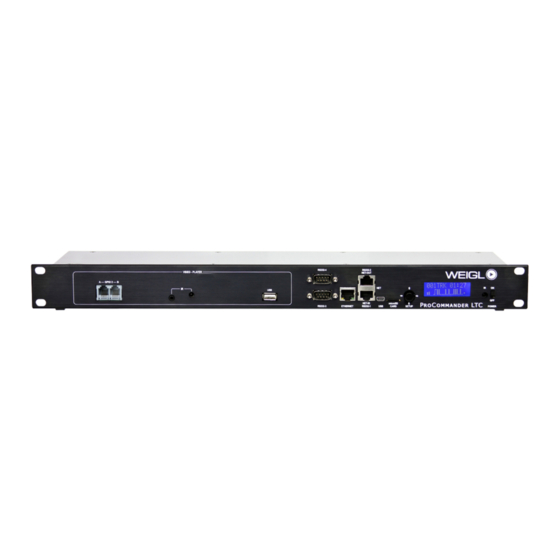
ETHERNET, RS232-1/NET-IN and RS232-2/NET-OUT INTERFACE The network port can be used for programming and configuration. Through the USB port you can configure or update the ProCommander LTC. Please make sure that you have installed the applicable driver. You can download them from... - Page 16 With the joystick a variety of menu modes can be controlled. The detailed description of the functions you can find here 5 Modification of the menu of ProCommander LTC. By moving the joystick to the left, right, up and down different menu items can be selected or modifications can be made.
- Page 17 ProCommander LTC pin assignments Modification in the menu can only be made if no show is running! A running show can be stopped by extended pressing the joystick (more than 3 seconds). After 3 seconds "End Show?" will be displayed. By a further confirmation with Enter the show is cancelled.
-
Page 18: Wemc-1 Procommander Back
You can make a firmware-update with the batch-file. Further information you can find here 6.4 Firmware 3.2 WEMC-1 ProCommander BACK update via batch-file. 3.2.1 Pin assignment for Open-Collector Circuit POWER The ProCommander LTC can be operated with voltages of 12V. - Page 19 Switching to output is done automatically by the ProCommander LTC, as soon as the channel is controlled by the control software with an analogue- or an ASCII-command. The resolution is 10-bit. If inductive loads (relays, solenoids, etc.) are connected, it is...
- Page 20 The maximum current per output must not exceed 2A. RS232-3 – 8 The serial interface RS232-3 – 8 of ProCommander LTC is assigned that a null-modem cable can be used for connection to a computer. AUDIO-OUT The output is a balanced audio signal, whereby Pin 2,3 are assigned to the left channel and Pin 4,5 to the right channel.
- Page 21 ProCommander LTC pin assignments Supply- and GND-Pins Schematic for output connection: At each Pin 5 of the 6-pole connector block the supply voltage of the power supply is brought out, if the Jumper K 14 is closed. Systematic is this connection open, in order that also an external...
- Page 22 ProCommander LTC pin assignments Jumper open Jumper closed...
- Page 23 ProCommander LTC pin assignments If the Jumper is closed and the power supply of the ProCommander LTC is used for the operation of the connected components, it is important to make sure, that the maximum total current must not exceed 500mA.
- Page 24 ProCommander LTC pin assignments...
-
Page 25: Usb - Driver Installation
USB – driver installation 4 USB – driver installation As soon as the ProCommander LTC is connected to your computer, Windows automatically search for the appropriate driver software. When you see this dialog box, select "Browse my computer for driver software". - Page 26 USB – driver installation If you receive the following security warning, confirm with "Install this driver software anyway".
- Page 27 USB – driver installation Then the driver software is installed. If the driver software has been installed successfully, the following dialog box will appear:...
- Page 28 USB – driver installation If you later want to elicit the COM-port, you will find this under "Control Panel" → "Device Manager" → "Ports (COM&LPT)".
-
Page 29: Modification Of The Menu Of Procommander Ltc
ProCommander LTC The functions of the menu are displayed on the display of the ProCommander LTC. This is directly controlled using the SETUP – joystick on the front panel. Therefore, the functions are divided into different LEVEL. As you venture deeper into the menu structure, the higher the number of the respective LEVELS. -
Page 30: Procommander Series
5.1 ProCommander Series Modification of the menu of ProCommander LTC LEVEL 1 is active as soon as "ProCom" is displayed. If you move the SETUP – joystick once down, the next function is displayed, in this case Start Show?. Pressing it again 5.2 Menu –... -
Page 31: Menu - Level 1
Modification of the menu of ProCommander LTC within 2 seconds. If no confirmation is received while the volume 5.2 Menu – LEVEL 1 is set, the next time the previously stored value is used again. Within the function "Menu" you can select between the menu items 5.2.1 MainSetup –... - Page 32 Set IP-Adrs – LEVEL 3 With the function "Set IP-Adrs" you can change the IP address of the ProCommander LTC. You have to activate "Set IP-Adrs" by pressing Enter. In the first line of the display "Set IP-Adrs:" appears, this corresponds to the LEVEL 4 of the menu plan.
- Page 33 Set Factory – LEVEL 3 With the function "Set Factory" you can restore to factory settings of the ProCommander LTC. Therefore you have to activate "Set Factory" by pressing Enter. You will be automatically be forwarded to LEVEL 4 of the menu plan.
-
Page 34: Configure - Level 2
Modification of the menu of ProCommander LTC 5.2.2 Configure – LEVEL 2... - Page 35 Modification of the menu of ProCommander LTC Based on LEVEL 2 you will be forwarded on LEVEL 3 by confirmation with Enter. LEVEL 3 locate under 5.2.2 Configure – LEVEL 2 following functions: LTC-TimeOut – LEVEL 3, EaseIn Time – LEVEL 3, StrtPlaylst –...
- Page 36 Modification of the menu of ProCommander LTC EaseIn Time – LEVEL 3 With the function "EaseIn Time" you can define the timespan which is used, to fade from the current analogue output value to the new value. The activation of the Ease-In function takes place by an abrupt jump within the show, as well as a change from one show to another.
- Page 37 Modification of the menu of ProCommander LTC In the first line of the display "Set StPlyL:" appears, this corresponds to the LEVEL 4 of the menu plan. The second line of the display shows the current value and corresponds to LEVEL 5 of the menu plan.
- Page 38 Modification of the menu of ProCommander LTC By moving the joystick to the left, you can return to a parent LEVEL. IgnStartClr – LEVEL 3 With the function "IgnStartClr" you can deactivate the automatic resetting of active outputs, when a new show starts.
-
Page 39: Audio - Level 2
Modification of the menu of ProCommander LTC 5.2.3 Audio – LEVEL 2 Based on LEVEL 2 you will be forwarded on LEVEL 3 by confirmation with Enter. LEVEL 3 locate under 5.2.3 Audio – LEVEL 2 following functions: Volume – LEVEL 3, Bass – LEVEL 3, Treble – LEVEL 3 and Fehler! Verweisquelle konnte nicht gefunden werden.. - Page 40 Modification of the menu of ProCommander LTC the display shows the current value and corresponds to LEVEL 5 of the menu plan. The * asterisk next to the value indicates that it is currently active. You can choose between the values of 0 to 31, the value "0"...
- Page 41 Modification of the menu of ProCommander LTC appears on the display confirm it by pressing Enter. Once the value is saved, an * asterisk will be displayed. By moving the joystick to the left, you can return to a parent LEVEL.
-
Page 42: Realtimeclk - Level 2
Modification of the menu of ProCommander LTC 5.2.4 RealTimeClk – LEVEL 2 Based on LEVEL 2 you will be forwarded on LEVEL 3 by confirmation with Enter. LEVEL 3 locate under 5.2.4 RealTimeClk – LEVEL 2 following functions: Hour – LEVEL 3, Minute – LEVEL 3, Day-Of-Week –... - Page 43 Hour – LEVEL 3 With the function "Hour" you can define the hour of the intern real time clock of the ProCommander LTC. You have to activate "Hour" by pressing Enter. In the first line of the display "Set Hour:" appears, this corresponds to the LEVEL 4 of the menu plan.
- Page 44 Minute – LEVEL 3 With the function "Minute" you can define the minute of the intern real time clock of the ProCommander LTC. You have to activate "Minute" by pressing Enter. In the first line of the display "Set Minute:" appears, this corresponds to the LEVEL 4 of the menu plan.
- Page 45 Day – LEVEL 3 With the function "Day" you can define the day of the intern real time clock of the ProCommander LTC. You have to activate "Day" by pressing Enter. In the first line of the display "Set Day:" appears, this corresponds to the LEVEL 4 of the menu plan.
- Page 46 Month – LEVEL 3 With the function "Month" you can define the month of the intern real time clock of the ProCommander LTC. You have to activate "Month" by pressing Enter. In the first line of the display "Set Month:" appears, this corresponds to the LEVEL 4 of the menu plan.
-
Page 47: Info - Level 2
Modification of the menu of ProCommander LTC You can choose beginning from the year 2012. You must move the joystick either up or down to set the requested year. If the value appears on the display confirm it by pressing Enter. - Page 48 Modification of the menu of ProCommander LTC Firmware Ver. – LEVEL 3 Here the current firmware version will be displayed, function not activated. SerialNumber – LEVEL 3 Here the current serial number will be displayed, function not activated. MAC-Address – LEVEL 3 Here the current MAC-Address will be displayed, function not activated.
-
Page 49: Procommander Ltc Configuration
6.1 USB port configuration You can configure the ProCommander LTC via USB through a terminal program, if the USB driver for the ProCommander LTC is correctly installed on your PC, a COM port will be activated when you connect them. If your driver is not already installed, Windows will prompt you when you connect it to. - Page 50 ProCommander LTC configuration You do not have to install the program. Copy the file from the zip-archive into a new folder and start WemcConfig.exe with double-click. After starting this window appears: Press the button "Scan for Devices" and the connected device...
- Page 51 With the button "Save Permanently" the new parameter are stored permanently in ProCommander LTC. By clicking "Save Temporarily" the new settings will be temporarily stored, when the device is switched off and on again, the original stored values...
- Page 52 10.0.0.101, and the subnet mask is 255.255.255.0. To connect your computer with the ProCommander LTC you have to change the network settings. For this purpose you open the network properties through the control panel. Chose the internet protocol version 4 and press the button...
-
Page 53: Firmware Update
With the button "FW Update Network" you can record the ProCommander LTC with the latest operating software. Connect the ProCommander LTC to the network interface of the computer. Start the configurator and search with the button "Scan for Devices" for the connected ProCommander LTC and... - Page 54 ProCommander LTC configuration In the following dialog you chose the new "ProLTC_Vxxx.hex" file. The data "Vxxx" corresponds to the latest version of the ProLTC.hex-file. This will be transferred to the ProCommander LTC. Attention: During this process do not close the configurator...
- Page 55 ProCommander LTC configuration...
- Page 56 ProCommander LTC configuration While the digits in the menu bar are running you can see on the display of the ProCommander "P's", which are running from the left to the right. As soon as the update was successful, "ProCom" appears on the display.
-
Page 57: Firmware Update Via Batch-File
ProLTC_V115.zip stands for the version 1.15 Connect the ProCommander LTC device through the USB- wire with the computer. If you are asked to install a driver, then choose the \usb\USBRS232driver\ folder, which you will find in your new folder, where you have unzipped the attached files. - Page 58 ProCommander LTC configuration In the display of the ProCommander LTC you should see "UPDATE UNIT! PLEASE WAIT!” The device firmware upgrade driver (DFU-driver) is not installed at this moment, if you run the update for the first time. So you will get a DOS-window like this: If the request for the driver installation is not shown ...
- Page 59 ProCommander LTC configuration The display of the ProCommander LTC will stay blank, don’t worry, you are asked for installing another driver. Now choose the C:\Program Files\Atmel\Flip 3.4.3\usb\ folder, where the atmel_usb_dfu.inf driver is located, which will be needed for the Update of the device firmware. It will be installed from Windows itself.
- Page 60 ProCommander LTC configuration...
-
Page 61: Dmx-Read In
DMX-univers can be merged into the internal generated DMX-signal. Furthermore, the integrated map function can be used to control the internal periphery of the ProCommander LTC via the external DMX-signal. So, all of the analogue-, servo-, the 8 PWM-, and the 16 digital output channels can be assigned to the external DMX-signal. - Page 62 DMX-Read in Both values will be compared and the highest value will be transferred into the output-signal. Merge Change: The value which had been changed as latest will be taken. Merge Add: Both values will be added and the sum will be transferred into the output-signal.
-
Page 63: Variable
Variable 8 Variable With variables decisions can be made, conditional show starts or counter can be realized. Variables can be manipulated inside a show or through external events. Possible actions are setting a value of a variable or executing mathematical operations like add, subtract, multiply or divide. - Page 64 Variable...
-
Page 65: Control.ini
Control.ini 9 Control.ini The Control.ini file is a new and easy way to assign different input events to any of the available ASCII-commands without any special show programming. It is even possible to assign an input event to several successive commands. An input event may be a change of the remote inputs, an infrared signal, a time event or a variable change. -
Page 66: I: Event Related To The Remote Inputs 1-16
Control.ini !i: Event related to the remote inputs 1-16 Example: !i1c → if input 1 is activated (c=close). !i1o → if input 1 is deactivated (o=open). !i1t → if input 1 changes (t=toggle). !k: Event related to the infrared remote control Example: !k1c →... - Page 67 Control.ini The character after the t determines the way the time should be interpreted. m is the absolute time after powering on the ProCommander LTC or after the insertion of a microSD card. After each removal or new insertion of the card this time is set to zero. &...
-
Page 68: Rc: Time-Controlled Events With The Internal Real Time Clock
Control.ini !rc: time-controlled events with the internal real time clock That you can use this function you have to insert a battery first, for further information go to 5.2.4 RealTimeClk – LEVEL 2. Based on the date and time values of the real time clock commands can be executed. -
Page 69: V: Variable Events
Control.ini All conditions have to be expressed within a round bracket () separated with a semicolon. Spaces within the round brackets are not allowed. Example: !rc(d=24;o=12;y=12):!rsn1# → December 24th 2012 runs Show 1 in normal mode. !rc(s&10):!….# → all 10 seconds the downstream command will be executed. - Page 70 Control.ini After each change of a variable the Control.ini file is checked, if an event is assigned to the variable. If this variable condition is true, the following command will be executed. Immediately after the input event, the command definition has to follow.
- Page 71 Control.ini The content of the Control.ini file can look like this: !i1c!ess1001!edv10:255# !i2c!esd3:"Hello World"# !i3o!epf1%20<2.5# !i4t!epl1_4%50# !k1c!rsa3# !i5c!cfm0<5# !i5o!cfm32<5# !tm01:20!rsn:\SHOW\001_SHOW.WM1# !t&05:00!rsn:2# !tc08:00!rsn:\SHOW\003_SHOW.WM1# line: if input 1 is closed, the open collector outputs 1 and 4 will be activated and additionally the channel 10 will be set to 255.
- Page 72 Control.ini line: with every level change of input 4, the PWM outputs 1 to 4 are set to value 50%. line: when the button 1 on the infrared remote control is pressed, the show "003_Show.WM1" starts from the "SHOWS" in add mode (show runs additionally to a running show) line: on activation of the input 5, the volume fades to 0 within 5 seconds.
-
Page 73: Playlist Functions
Playlist functions 10 Playlist functions Audio files for the ProCommander LTC must be OGG Vorbis format. For converting audio formats to OGG Vorbis, seek appropriate software. Both ConductorPro VenueMagic software automatically generate OGG Vorbis files. The ProCommander LTC can manage multiple playlists. The playlists are stored in the folder called PLAYLxxx. - Page 74 Playlist functions !psp# is the pause command. A running soundtrack is put in pause mode. It does not matter whether the soundtrack is playing because of a playlist function, or a show has started the track. This command affects only the soundtrack and does not affect a possible running show.
-
Page 75: Folder Structure Of The Flash Card
Folder structure of the Flash Card 11 Folder structure of the Flash Card To begin shows, audio files, or respectively playlists, folder and file names have to follow a predefined order. Generally, only one subdirectory is supported. All shows must therefore be in the "SHOWS" folder. The first three characters of the show name must have a number in the range of 001-999. - Page 76 Folder structure of the Flash Card is played automatically after powering on the ProCommander LTC, if the menu function StrtPlaylst – LEVEL 3 is activated.
-
Page 77: Programming The Procommander Ltc
Programming the ProCommander LTC 12 Programming the ProCommander LTC Due to the open interface protocol, there are various software programs that support the ProCommander LTC. Please refer to the manual of the respective software to learn how to program the ProCommander LTC. - Page 78 Programming the ProCommander LTC...
-
Page 79: Interface Protocols
Interface protocols 13 Interface protocols The ProCommander LTC can be controlled in a variety of ways. To allow a broad range of applications to control the ProCommander LTC, an easy-to-understand and simple-to- handle ASCII-protocol has been introduced. In addition, there is an open HEX protocol designed for short commands. - Page 80 Interface protocols...
-
Page 81: Appendix
Appendix 14 Appendix 14.1 Pin assignment RS232-3 – 8 Connector RS232- RS232- RS232- RS232- RS232- RS232- Pin 1 N.C. N.C. N.C. N.C. N.C. N.C. Pin 2 Pin 3 Pin 4 N.C. N.C. N.C. N.C. N.C. N.C. Pin 5 Pin 6 N.C. -
Page 82: Pin Assignment Audio-Out
14.2 Pin assignment AUDIO-OUT Appendix Connector Function Pin 1 Pin 2 Audio-Out-LEFT - Pin 3 Audio-Out-LEFT + Pin 4 Audio-Out-RIGHT - Pin 5 14.3 Pin assignment DMX-OUT Audio-Out-RIGHT + Connector Function Pin 1 Pin 2 DMX-OUT - Pin 3 DMX-OUT + Pin 4 DMX-IN - Pin 5... -
Page 83: Pin Assignment Input 1-16
14.4 Pin assignment Input 1-16 Appendix Input 1-8/ Input 9-16 Connector Upper Row Lower Row Input 1 Input 9 Input 2 Input 10 Input 3 Input 11 Input 4 Input 12 Input 5 Input 13 Input 6 Input 14 Input 7 Input 15 Input 8 Input 16... -
Page 84: Pin Assignment Open-Collector 1-16
14.5 Pin assignment Open-Collector 1-16 Appendix Digital Out 1-4/ Digital Out 5-8 Connector Upper Row Lower Row Open-Collector 1 Open-Collector 5 Open-Collector 2 Open-Collector 6 Open-Collector 3 Open-Collector 7 Open-Collector 4 Open-Collector 8 Common Cathode Common Cathode 1 If jumper K 14 is closed, than Pin 5 is connected with the power supply +. Supply- and GND-Pins 2 If jumper K 14 is closed, than Pin 5 is connected with the power supply +. -
Page 85: Index
Index 15 Index Day-Of-Week ..See RealTimeClk DMX-OUT-IN ......19 DMX-Read in......64 Audio Bass ........42 Treble ........43 Volume ........41 EaseIn Time ..... See Configure AUDIO-OUT ........21 ETHERNET ........15 Bass ........ See Audio FCC and CE Compliance ....9 FCC DECLARATION OF CONFORMITY ...... - Page 86 Index Merge-function ... See DMX-Read in Info Firmware Ver......50 microSD ........16 Minute ....See RealTimeClk IP-Address ......51 MAC-Address ......51 Modification of the menu ..30 Menu ........32 Port ........51 SerialNumber ......51 ProCommander Series ..31 Month ....
- Page 87 Index Day-Of-Week ......47 Hour ........45 Minute ........46 USB ..........16 Month ........48 USB – driver installation .... 26 Year ........49 USB port configuration ..... See REMOTE 1-8 / 9-16 .....20 Configuration RS232-1/NET-IN ......15 RS232-2/NET-OUT ......15 RS232-3 – 8 ........21 RS485-2 Drv ..... See Configure Variable ........
Need help?
Do you have a question about the ProCommander LTC and is the answer not in the manual?
Questions and answers